manuals.online logo
Brands
  1. Home
  2. •
  3. Brands
  4. •
  5. Nidek Medical
  6. •
  7. Medical Equipment
  8. •
  9. Nidek Medical AR-360A User manual

Nidek Medical AR-360A User manual

This manual suits for next models

5

Other Nidek Medical Medical Equipment manuals

Nidek Medical ARK-530A User manual

Nidek Medical

Nidek Medical ARK-530A User manual

Nidek Medical RT-5100 User manual

Nidek Medical

Nidek Medical RT-5100 User manual

Nidek Medical Max 30 3005 User manual

Nidek Medical

Nidek Medical Max 30 3005 User manual

Nidek Medical HandyRef-K User manual

Nidek Medical

Nidek Medical HandyRef-K User manual

Nidek Medical Mark 5 Plus User manual

Nidek Medical

Nidek Medical Mark 5 Plus User manual

Nidek Medical ARK-530 User manual

Nidek Medical

Nidek Medical ARK-530 User manual

Nidek Medical ConfoScan4 User manual

Nidek Medical

Nidek Medical ConfoScan4 User manual

Nidek Medical NT-2000 User manual

Nidek Medical

Nidek Medical NT-2000 User manual

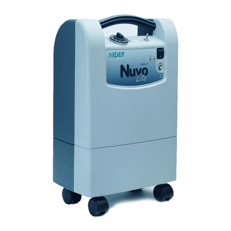
Nidek Medical Mark 5 Nuvo Lite Series User manual

Nidek Medical

Nidek Medical Mark 5 Nuvo Lite Series User manual

Nidek Medical Mark 5 Nuvo Lite User manual

Nidek Medical

Nidek Medical Mark 5 Nuvo Lite User manual

Nidek Medical RT-3100 User manual

Nidek Medical

Nidek Medical RT-3100 User manual

Nidek Medical AR-600 User manual

Nidek Medical

Nidek Medical AR-600 User manual

Nidek Medical Mark 5 Nuvo Lite Family User manual

Nidek Medical

Nidek Medical Mark 5 Nuvo Lite Family User manual

Nidek Medical GYC-1000 User manual

Nidek Medical

Nidek Medical GYC-1000 User manual

Nidek Medical Lex 1000 Guide

Nidek Medical

Nidek Medical Lex 1000 Guide

Nidek Medical RS-3000 User manual

Nidek Medical

Nidek Medical RS-3000 User manual

Nidek Medical NT-510 User manual

Nidek Medical

Nidek Medical NT-510 User manual

Nidek Medical ARK-500A User manual

Nidek Medical

Nidek Medical ARK-500A User manual

Nidek Medical LT-980 User manual

Nidek Medical

Nidek Medical LT-980 User manual

Nidek Medical Nuvo 10 User manual

Nidek Medical

Nidek Medical Nuvo 10 User manual

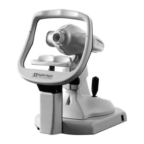
Nidek Medical Magellan Mapper User manual

Nidek Medical

Nidek Medical Magellan Mapper User manual

Nidek Medical AR-310A User manual

Nidek Medical

Nidek Medical AR-310A User manual

Nidek Medical TONOREF II Manual

Nidek Medical

Nidek Medical TONOREF II Manual

Nidek Medical ARK-700 Series User manual

Nidek Medical

Nidek Medical ARK-700 Series User manual

Popular Medical Equipment manuals by other brands

Itamar Medical WatchPAT Operation manual

Itamar Medical

Itamar Medical WatchPAT Operation manual

PROTEOR 1P650 KNEE Assembling and adjustment instructions

PROTEOR

PROTEOR 1P650 KNEE Assembling and adjustment instructions

Liberate Medical VentFree user manual

Liberate Medical

Liberate Medical VentFree user manual

Dicarre DA20 user guide

Dicarre

Dicarre DA20 user guide

Stryker Medical M Series Operation manual

Stryker Medical

Stryker Medical M Series Operation manual

Invacare ScanBed 750 user manual

Invacare

Invacare ScanBed 750 user manual

Getinge Arjohuntleigh Nimbus 3 Professional Instructions for use

Getinge

Getinge Arjohuntleigh Nimbus 3 Professional Instructions for use

Mettler Electronics Sonicator 730 Maintenance manual

Mettler Electronics

Mettler Electronics Sonicator 730 Maintenance manual

Pressalit Care R1100 Mounting instruction

Pressalit Care

Pressalit Care R1100 Mounting instruction

Denas MS DENAS-T operating manual

Denas MS

Denas MS DENAS-T operating manual

bort medical ActiveColor quick guide

bort medical

bort medical ActiveColor quick guide

AccuVein AV400 user manual

AccuVein

AccuVein AV400 user manual

agiliti NP Trio user manual

agiliti

agiliti NP Trio user manual

Rocket Medical Rocket Digital Oocyte Aspiration Pump Service manual

Rocket Medical

Rocket Medical Rocket Digital Oocyte Aspiration Pump Service manual

Monteris Medical Neuroblate Instructions for use

Monteris Medical

Monteris Medical Neuroblate Instructions for use

Otto Block 8E33 7 manual

Otto Block

Otto Block 8E33 7 manual

ADVANCED HOME CARE Helios Guide

ADVANCED HOME CARE

ADVANCED HOME CARE Helios Guide

NeuLog NUL-208 Guide

NeuLog

NeuLog NUL-208 Guide

manuals.online logo
manuals.online logoBrands
  • About & Mission
  • Contact us
  • Privacy Policy
  • Terms and Conditions

Copyright 2025 Manuals.Online. All Rights Reserved.

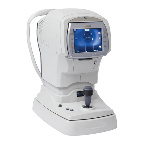
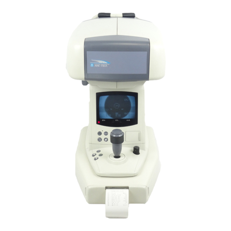
AUTO REFRACTOMETER,AUTO REF/KERATOMETER
Model AR-360A,AR-330A,
AR-310A, ARK-560A
ARK-530A, ARK-510A
SERVICE MANUAL
November 2010
Pages in total: 172
XAR17ARDA001E/E
NIDEK CO., LTD. : 34-14, Maehama, Hiroishi-cho, Gamagori, Aichi 443-0038, Japan
(Manufacturer) Telephone: (81-533) 67-6611
Facsimile: (81-533) 67-6610
NIDEK CO., LTD : 3F Sumitomo Fudosan Hongo Bldg., 3-22-5, Hongo,
(Tokyo Office) Bunkyo-Ku, Tokyo 113-0033, Japan
Telephone: (81-3) 5844-2641
Facsimile: (81-3) 5844-2642
NIDEK INCORPORATED : 47651 Westinghouse Drive, Fremont, California 94539, U. S. A.
(United States Agent) Telephone: (510) 226-5700
Facsimile: (510) 226-5750
NIDEK SOCIETE ANONYME : Europarc 13, rue Auguste Perret, 94042 CRETEIL, France
(EU Authorized Representative) Telephone: (01) 49 80 97 97
Facsimile: (01) 49 80 32 08
Table of Contents
§1 INTRODUCTION..............................................................................1-1
§2 SAFETY PRECAUTIONS ................................................................2-1
§3 TROUBLESHOOTING.....................................................................3-1
§4 SUBTROUBLESHOOTING .............................................................4-1
4.1 Screen is not Turned On.......................................................................................... 4-1
4.2 Arrow does not Disappear. ...................................................................................... 4-2
4.3 Charge Indicator does not Disappear...................................................................... 4-2
4.4 Horizontal Movement of Main Unit is not Sluggish.................................................. 4-3
4.5 Main Unit cannot Move Horizontally. ....................................................................... 4-3
4.6 Eye Indication of R (right)/L (left) cannot be Toggled. ............................................. 4-4
4.7 Measuring Unit cannot be Moved Up or Down by Rotating Joystick. ..................... 4-5
4.8 Measuring Unit Stops with a Jerk at Top or Bottom Position................................... 4-5
4.9 Measuring Unit Rattles. ........................................................................................... 4-6
4.10 Chinrest does not Move Smoothly......................................................................... 4-6
4.11 Fixation Lamp cannot be Seen through Air Nozzle. .............................................. 4-6
4.12 Air is not Puffed Out by Pressing Start Button....................................................... 4-7
4.13 Operating Noise of Piston is Abnormal.................................................................. 4-8
4.14 Alignment Spot does not Appear. .......................................................................... 4-8
4.15 AL2 LED for Forward/Backward Movement does not Light Up............................. 4-8
4.16 LEDs for Eyelid Detection and Illumination do not Light Up.................................. 4-9
4.17 Alignment is not Performed Automatically in F.AUTO Mode. ................................ 4-9
4.17.1 Right/left alignment is not performed (“Err X” appears). ............................. 4-9
4.17.2 Up/down alignment is not performed. ........................................................ 4-10
4.17.3 Forward/backward alignment is not performed (“Err Z” appears).............. 4-10
4.18 OPEN THE EYE WIDERAppears........................................................................4-11
4.19 NO SEARCHING Appears....................................................................................4-11
4.20 Measurement does not Start even when Alignment and Focusing are Complete.4-12
4.21 Error Messages Appear. ...................................................................................... 4-13
4.21.1 Error “BLK” often appears.......................................................................... 4-13
4.21.2 Error “ALM” often appears. ........................................................................ 4-13
4.21.3 Error “APL” often appears.......................................................................... 4-14
4.21.4 Error “PCE” often appears. ........................................................................ 4-15
4.21.5 Error “OVR” often appears......................................................................... 4-15
4.21.6 Error “PRS” often appears. ........................................................................ 4-16
4.22 Low Confidence Data (Data with ALM or APL) are often Obtained..................... 4-16
4.23 Measured Data is Abnormal. ............................................................................... 4-16
4.24 PRINT ERRORAppears on Screen and Printing cannot be Performed. ............ 4-17
4.25 Print is Blurred. .................................................................................................... 4-18
4.26 Measured Data cannot be Transferred................................................................ 4-19
4.27 Monitor Auto Off Function does not Operate....................................................... 4-19
4.28 PRESSURE ERROR Appears in Test Mode. ...................................................... 4-20
4.29 Voltage Supply Line of LED Power Supply.......................................................... 4-21
4.30 Voltage Supply Line of Power Supply.................................................................. 4-22
§5 CLEANING LENSES ETC. ..............................................................5-1
5.1 Observation Window ............................................................................................... 5-1
5.2 Inner Window........................................................................................................... 5-1
5.3 Air nozzle ................................................................................................................. 5-1
§6 REMOVING PROCEDURES ...........................................................6-1
6.1 Right and Left Covers.............................................................................................. 6-1
6.2 Front Cover.............................................................................................................. 6-1
6.3 Covers ..................................................................................................................... 6-1
6.4 Rear Cover .............................................................................................................. 6-2
6.5 Monitor Panel .......................................................................................................... 6-2
6.6 Bottom Plate ............................................................................................................ 6-2
§7 REPLACEMENT PROCEDURES....................................................7-1
7.1 Main Board .............................................................................................................. 7-1
7.2 Driver Board............................................................................................................. 7-2
7.3 LED Board and PLS Board...................................................................................... 7-3
7.4 SW Board ................................................................................................................ 7-4
7.5 UDPOS Board ......................................................................................................... 7-4
7.6 POS Board............................................................................................................... 7-4
7.7 Printer Board ........................................................................................................... 7-5
7.8 Transformer ............................................................................................................. 7-6
7.9 Joystick.................................................................................................................... 7-6
7.10 Up/Down Movement Motor Unit ............................................................................ 7-7
7.11 LCD Unit ................................................................................................................ 7-7
7.12 Cleaning and Replacing Slide Plate ...................................................................... 7-8
7.13 Measuring Unit ...................................................................................................... 7-8
7.14 Pressure Sensor.................................................................................................... 7-9
7.15 Up/Down Movement Bearing................................................................................. 7-9
7.16 Replacing Rod End and Cleaning Piston and Cylinder....................................... 7-10
7.16.1 Checking tightness of spherical inside ring................................................ 7-10
7.16.2 Replacing rod end...................................................................................... 7-10
7.16.3 Cleaning piston and cylinder...................................................................... 7-10
7.17 CCD Camera ........................................................................................................7-11
7.18 Safe Switch (EA25) ..............................................................................................7-11
7.19 Motor for Right/Left Movement ............................................................................ 7-12
7.20 Motor for Forward/Backward Movement ............................................................. 7-12
7.21 Rack..................................................................................................................... 7-12
7.22 Pinion................................................................................................................... 7-13
7.23 FIX LED ............................................................................................................... 7-13
7.24 R Switch............................................................................................................... 7-14
7.25 Front Stopper Switch ........................................................................................... 7-14
7.26 P.S. Board............................................................................................................ 7-15
7.27 BA05 Replacement Unit for EMC ........................................................................ 7-17
7.28 Fixing Knob.......................................................................................................... 7-19
§8 ADJUSTMENT.................................................................................8-1
8.1 Setting Time and Date ............................................................................................. 8-1
8.2 Adjusting Camera Position ...................................................................................... 8-1
8.3 Adjusting Video Signal Level ................................................................................... 8-2
8.4 Adjusting Camera Focus ......................................................................................... 8-2
8.5 Adjusting Focus and Position of Optical Reticle...................................................... 8-3
8.6 Adjusting AL2 LED Optical Axis ............................................................................... 8-4
8.7 Adjusting Optical Axis of Applanation Detector........................................................ 8-5
8.8 Electric Adjustment .................................................................................................. 8-6
8.8.1 Adjusting AL2 LED offset voltage................................................................... 8-6
8.8.2 Adjusting comparison voltage ........................................................................ 8-6
8.8.3 Adjusting AL1 LED light amount..................................................................... 8-7
8.9 Adjusting Reference Marker Position ...................................................................... 8-8
8.10 Adjusting PSD Balance.......................................................................................... 8-9
8.11 Adjusting Fixation Lamp Position......................................................................... 8-10
8.12 Adjusting Pressure of Puffed Out Air ....................................................................8-11
8.13 Adjusting Solenoid Brake..................................................................................... 8-12
8.14 Adjusting Front Cover LED Light ......................................................................... 8-13
8.15 Adjusting Applanation Detector ........................................................................... 8-14
8.16 Adjusting Camera Position (Second time)........................................................... 8-15
8.17 Adjusting Reference Marker Position (Second time)........................................... 8-15
8.18 Electric Adjustment (Second time) ...................................................................... 8-15
8.19 Adjusting PSD Balance (Second time) ............................................................... 8-15
8.20 Checking AL2 LED Adjustment............................................................................ 8-16
8.21 Adjusting Electronic Reticle Position ................................................................... 8-17
8.22 Checking OPEN THE EYE WIDER ..................................................................... 8-18
8.23 Checking Successive Air Puffing ......................................................................... 8-18
8.24 Adjusting Three-Point Tightening of Up/Down Movement Bearing ..................... 8-19
8.25 Adjusting Up/Down Movement of Measuring Unit ............................................... 8-20
8.25.1 Tighteness of nut holder............................................................................. 8-20
8.25.2 Feed screw holder for up/down movement................................................ 8-20
8.26 Adjusting Chinrest Up/Down Movement.............................................................. 8-21
8.27 Adjusting Pulse Wave .......................................................................................... 8-21
8.28 Adjusting A Constant and B Constant.................................................................. 8-22
8.29 Checking Measuring Unit Position ...................................................................... 8-23
8.30 Measuring Model Eye.......................................................................................... 8-24
8.30.1 Electric model eye...................................................................................... 8-24
8.30.2 Silicone model eye..................................................................................... 8-24
§9 SUPPLEMENT.................................................................................9-1
9.1 Wiring Diagram........................................................................................................ 9-1
9.2 Error Message ......................................................................................................... 9-2
9.3 External View........................................................................................................... 9-3
9.4 Labels ...................................................................................................................... 9-4
9.5 Tools and Consumables List.................................................................................... 9-5
1 - 1
XAR17ARDA001E/E
• This service manual is for the NIDEK AUTO REFRACTOMETER and AUTO REF/
KERATOMETER models: AR-360A, AR-330A, AR-310A, ARK-560A, ARK-530A and ARK-
510A.
• For correct service, thorough understanding of the contents of this manual is required prior to
the service.
• Refer to the operator’s manual and parts list for the AR-360A, AR-330A, AR-310A, ARK-
560A, ARK-530A and ARK-510A.
• Refer to the Service Manual Annex for important changes.
• In case the device cannot be repaired according to the procedures described in this manual,
please report the serial number of the device and details of the symptom or symptoms.
§1 INTRODUCTION
1 - 2
XAR17ARDA001E/E
[This page is intentionally left blank.]
2 - 1
XAR17ARDA001E/E
<General precautions>
• Servicing should be performed by NIDEK service persons or other qualified personnel.
• Perform all servicing according to the procedures described in this manual.
Failure to do so may cause unexpected accident or malfunction.
• When performing maintenance work, turn off the power switch and disconnect the power
cord from the wall outlet unless the power needs to be on.
• Never wipe the covers by using an organic solvent such as paint thinner. Doing so may ruin
the surface and damage the appearance of the device.
• Invisible laser (class 3B laser) is used. (* This device is classified to a Class 1 laser product
and does not emit laser harmful to eyes.)
<Maintenance precautions>
• Never look at the laser beam (invisible laser: class 3B) from the phototransmitter ASSY.
directly or touch it.
• In case of system malfunction, check the symptom and turn the power switch off.
• Never drop parts or screws inside the system, nor bump it against surrounding objects.
• Prepare storage cases so as not to lose the removed screw or parts.
• Screw or unscrew the screws with proper tools.
• After loosening the screws fastened by a threadlocking adhesive, be sure to reapply the
threadlocking adhesive to the screws when retightening them.
• After replacing parts, make sure that they are fixed securely before turning on the power .
• Should you observe strange odors or smoke being issued from the system, immediately turn
off the power switch, disconnect the power cord from the outlet, and investigate the cause.
If the system is powered in abnormal conditions, fire, electric shock, or total loss of the
system may result.
• See “8.1 Wiring Diagram” and “8.2 Connector Cable” for checking cable breaks described in
TROUBLESHOOTING. In addition, check cables for the following:
(1) Connectors are connected and crimped securely.
(2) No contact failure occurs after re-connection of connectors.
(3) Cables are soldered properly.
Do not yank the cables with excessive force. Doing so could cause cable breakage.
Do not perform servicing with wet hands. Doing so could cause electric shock or malfunction.
<Adjustment precautions>
• Perform adjustment on a vibration-free, level, and stable surface.
A slanted floor or place subject to vibration will obstruct accurate adjustment.
• Do not use adjustment jigs for puropses other than those intended.
§2 SAFETY PRECAUTIONS
2 - 2
XAR17ARDA001E/E
[This page is intentionally left blank.]