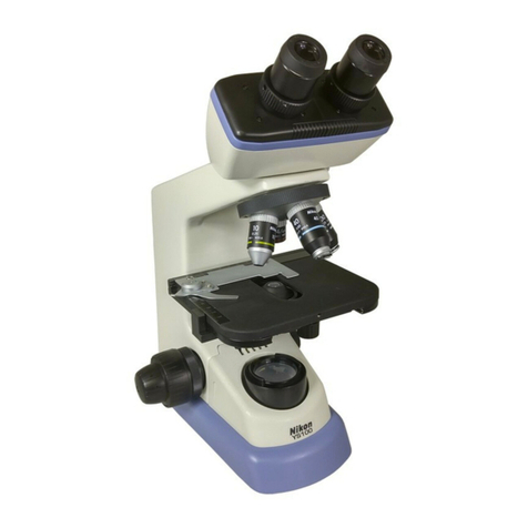
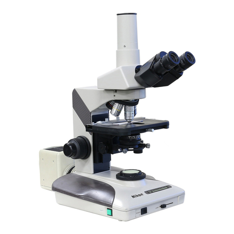
Nikon SC User manual

Nikon
MICROSCOPE
MODEL
SC
Instructions
NIPPON
KOGAKU
K.K.

CAUTIONS
IN
HANDLING
CARE
AND
MAINTENANCE
^
Red-colored
lock
screw
Before
handling
the
microscope,
be
sure
to
remove
the
red-colored
lock
screw.
Exchanging
the
lamp
bulb
and
fuse
Before
replacing
the
lamp
bulb
or
fuse,
be
sure
to
turn
the
power
switch
to
OFF
and
pull
out
the
power
source
cord
from
the
socket.
^
Place
for
using
Avoid
the
use
of
microscope
in
a
dusty
place,
where
it
is
subject
to
vibrations
or
exposed
to
high
temperatures,
moisture
or
direct
sunlight.
^
Dirt
on
the
lens
Do
not
leave
dust,
dirt
or
finger
marks
on
the
lens
surfaces.
They
will
prevent
you
from
clear
observa¬
tion
of
the
specimen
image.
e
Avoid
sharp
knocks!
Handle
the
microscope
gently,
taking
care
to
avoid
sharp
knocks.
Use
SC
type
objectives
&
eyepieces
For
the
SC
microscope,
use
no
other
objec¬
tives
and
eyepieces
that
of
SC
type.
^
Cleaning
the
lenses
To
clean
the
lens
surfaces,
remove
dust
using
a
soft
hair
brush
or
gauze.
Only
for
removing
finger
marks
or
grease,
should
soft
cotton
cloth,
lens
tissue
or
gauze
light¬
ly
moistened
with
absolute
alcohol
(eth¬
anol
or
methanol)
be
used.
For
cleaning
the
objectives
and
immersion
oil
only
use
xylene.
Observe
sufficient
caution
in
handling
alcohol
and
xylene.
0
Cleaning
the
painted
surfaces
Avoid
the
use
of
any
organic
solvent
(For
example;
thinner,
xylene,
ether,
alcohol
etc.)
for
cleaning
the
painted
surfaces
and
plastic
parts
of
the
instrument.
0
Never
attempt
to
dismantle!
Never
attempt
to
dismantle
the
instrument
so
as
to
avoid
the
possibility
of
impairing
the
operational
efficiency
and
accuracy.
Q
When
not
in
use
When
not
in
use
cover
the
instrument
with
the
accessory
vinyl
cover
or
put
in
the
case
(available
on
order)
and
store
it
in
a
place
free
from
moisture
and
fungus.
Periodical
checking
To
maintain
the
performance
of
the
instru¬
ment,
we
recommend
the
customers
to
check
the
instrument
periodically.
For
details,
contact
our
dealers.

CONTENTS
I.
NOMENCLATURE
AND
FUNCTION.
4
II.
ASSEMBLY.
g
1.
Attaching
the
eyepiece
tube.
g
2.
Attaching
the
eyepiece.
g
3.
Attaching
the
mechanical
stage.
0
4.
Attaching
the
objectives.
0
5.
Attaching
the
condenser.
y
6
.
Attaching
the
lamp
bulb.
7
7.
Attaching
the
lamp
bulb
for
simplified
illumination
.
,
7
III.
OBSERVATION.
0
1.
Setting
the
specimen
in
position.
g
2.
Adjusting
the
illumination.
g
3.
Adjusting
interpupillary
distance.
g
4.
Adjusting
for
eyesight
difference.
g
5.
Coarse
focusing.
,
,
g
6
.
Fine
focusing.
g
7.
Working
distance
of
objectives.
g
8
.
Vertical
movement
of
condenser.
1
q
9.
Condenser
diaphragm.
.
|q
10.
Oil-immersion
observation.
11.
Moving
the
glass
si
ide.
1
0
IV.
OPTICAL
FEATURES
OF
SC
MICROSCOPE.H
V.
TROUBLE
SHOOTING
CHART.
1
2
1.
Optical
system
.
12
2
Manipulation
system
.
13
3.
Electrical
system
.
14
ELECTRIC
SPECIFICATIONS.
15

I
.
NOMENCLATURE
AND
FUNCTION
The
descriptions
in
this
instruction
manual,
for
the
most
part,
cover
the
use
of
the
binocular
eyepiece
lube
microscope.
They
are
applicable,
except
where
not
specified,
to
the
monocular
eyepiece
type
as
well.
Coarse
focus
knob
Power
cord
SC
eyepiece
Diopter
ring
_
Used
for
eyesight
adjustment.
Binocular
eyepiece
tube
Arm
One
rotation
moves
the
stage
about
24mm.
Fine
focus
knob
Diaphragm
control
ring
Condenser
focus
knob
Microscope
base
Eyepiece
sleeve
Hold
the
sleeves,
when
adjusting
interpupillary
distance.
Revolving
nosepiece
Accepts
4
objectives-
SC
objective
Range'.
2.2mm
One
rotation
moves
the
stage
about
0.2mm.
Power
switch
and
brightness
control
dial
More
brightness
is
obtained
by
turning
toward
the
thicker
end
of
the
arrow.
Condenser
Fig.
1
4

Slide
holder
Mechanical
stage
Range:
38
x
76mm
Filter
holder
For
filters
of
33mm
in
diarrwter.
Filter
receptacle
_
For
filters
of
45mm
in
diameter.
Stage
Y-axis
travel
knob
Stage
X-axis
travel
knob
Condenser
clamp
screw
For
locking
the
condenser.
For
tightening,
use
the
tool.
Eyepiece
tube
clamp
screw
Lightly
released,
the
tube
is
rotatable.
Fig.
2
tube
Stage
clip
For
holding
the
specimen
in
position
illuminator
Fig.
3
5

II.
ASSEMBLY
Before
handling
the
microscope,
remove
the
red-
colored
lock
screw.
(Fig.
4)
1.
Attaching
the
eyepiece
tube
(Fig.
5)
i;
Slacken
the
eyepiece
tube
clamp
screw
suf¬
ficiently.
2)
Tilting
the
eyepiece
tube
as
^own
in
Fig.
5,
seat
it
in
a
horizontal
position.
3)
Fasten
up
the
clamp
screw
securely.
2.
Attaching
the
eyepiece
(Fig.
6)
1)
Remove
the
dust
caps
from
the
tubes.
2
)
Screw
in
the
eyepieces.
3;
To
avoid
accidental
release,
screw
the
eye¬
piece
in
firmly,
using
a
rubber
sheet
or
the
like
to
hold
the
eyepiece.
3.
Attaching
the
mechanical
stage
(Fig.
7)
1}
Place
the
mechanical
stage
on
the
stage
mount
so
that
the
travel
knobs
are
on
the
right
side
of
an
operator
facing
the
stage.
2)
Fasten
the
stage
from
the
bottom
with
the
two
4mm
hexagonal
hole
bolts,
using
tool
A.
4.
Attaching
the
objectives
(Fig.
8)
1)
Screw
the
objectives
into
the
revolving
nose-
piece
in
such
order
that,
as
the
nosepiece
is
rotated
clockwise,
an
objective
of
higher
magnifying
power
enters
the
optical
path.
2)
For
avoiding
accidental
release,
it
is
possible
to
lock
them
tightly
using
tool
C,
Eyepiece
tube
clamp
screw
Tool
C
Mechanical
stage
Travel
knobs
Revolvmg
nosepiece
6

5.
Attaching
the
condenser
1}
Place
the
blue
filter
into
the
filter
holder.
(Fig.
9)
21
Slide
the
condenser
into
its
mount
as
far
as
it
will
go
in
position
where
the
aperture
number
plate
turns
toward
the
operator.
3)
Tighten
the
condenser
clamp
screw,
using
the
tool
B.
(Fig.
10)
Note:
The
tools
A,
B
and
C
(Fig.
11)
are
not
included
in
the
microscope
set.
If
necessary,
purchase
them
independ¬
ently.
6
.
Attaching
the
lamp
bulb
The
microscope
is
delivered
with
its
lamp
bulb
(100V,
115/125
or
220/240V-30W)
attached.
If
it
is
necessary
to
replace
the
bulb
at
a
later
time,
proceed
as
below;
Be
sure
to
remove
the
power
cord
from
the
socket,
beforehand.
1)
Lay
the
instrument
down
carefully
to
permit
unscrewing
the
set
screw
found
on
the
bottom
lid
of
the
microscope.
A
screw
driver
or
coin
may
be
used.
2)
Sliding
the
bottom
lid
to
the
side
of
the
set
screw,
remove
it.
The
lamp
bulb
will
then
be
accessible.
(Fig.
12)
3)
To
attach
the
bulb,
pushing
the
lamp
bulb
with
its
silver
surface
turned
to
the
side
of
the
bottom
lid
insert
the
bulb
into
the
socket.
(Fig.
13)
Note:
Finger
marks
left
on
the
lamp
bulb
sur¬
face
will
decrease
the
brightness
of
image.
In
handling
the
bulb,
use
a
cloth
or
wear
gloves.
4)
Replace
the
bottom
lid.
7.
Attaching
the
lamp
bulb
for
simplified
il¬
lumination
(Fig,
14)
This
lamp
bulb
(110/120V-10W
or
220/240V
-
12W)
is
to
be
used
exclusively
for
the
monoc¬
ular
eyepiece
tube
type
of
microscope.
1)
Be
sure
to
remove
the
power
cord
from
the
socket.
2)
Remove
the
lamp
socket
from
the
instru¬
ment
by
turning.
3)
Screw
the
lamp
bulb
into
the
socket
as
far
as
it
will
go.
4)
Reattach
the
socket.
Condenser
clamp
screw
Condenser
Bottom
lid
Aperture
number
plate
Fig.
to
1
A
B
c
1
1
Tools
available
on
order
Fig.
12
Silver
surface
of
the
lamp
bulb
Fig.
14
7

III.
OBSERVATION
1.
Setting
the
specimen
in
position
1)
Place
the
specimen
on
the
stage
holding
in
position
by
means
of
the
slide
holder.
{Fig.
15)
2)
When
not
using
the
mechanical
stage,
hold
the
specimen
securely
with
the
two
stage
clips.
(Fig.
16)
2.
Adjusting
the
illumination
1)
Insert
the
power
cord
into
the
socket.
2)
Raise
the
condenser
to
its
upper
limit,
and
fully
open
the
condenser
diaphragm.
3)
Turn
the
power
switch
&
brightness
control
dial
to
light
the
lamp,
(Fig.
17)
Brightness
is
increased
by
turning
toward
the
thicker
end
of
the
arrow,
and
decreased
to¬
ward
the
thinner.
4)
Rotate
the
revolving
nosepiece
to
swing
the
4X
or
10X
objective
into
the
optical
path.
At
this
time,
make
sure
that
the
objective
clicks
properly
into
position,
3.
Adjusting
interpupillary
distance
(Fig.
18)
When
using
a
binocular
eyepiece
tube,
adjust
the
interpupillary
distance,
so
that
both
the
right
and
left
viewfields
become
one.
4.
Adjusting
for
eyesight
difference
(Fig.
19)
1)
First,
viewing
into
the
right
eyepiece
with
the
lOX
objective
in
position,
manipulate
the
coarse
and
fine
focus
knobs
to
bring
the
specimen
into
focus.
2}
Then,
viewing
into
the
left
eyepiece,
turn
the
diopter
ring
to
bring
the
image
into
sharp
focus,
without
manipulating
the
focus
knobs.
0
index
is
put
on
the
diopter
ring.
Stage
clips
Fig.
16
8

5.
Coarse
focusing
1)
The
coarse
focus
knob
is
to
be
used
for
coarse
focusing
and
for
fine
focusing
with
the
4X
objective.
2)
It
can
also
be
used
for
lowering
the
stage
convenience
when
replacing
a
specimen,
removing
immersion
oil.
etc.
3)
The
relation
between
the
direction
of
rota¬
tion
of
the
coarse
focus
knob
and
that
of
vertical
movement
of
the
stage
is
as
indicat¬
ed
by
the
arrows
in
Fig.
20-A.
B.
6
.
Fine
Focusing
1)
The
fine
focus
knob
is
to
be
used
for
fine
focusing
with
the
10X
or
higher
power
objectives.
2
)
It
is
also
used
when
exchanging
objectives
or
focusing
on
each
successive
layer
of
a
thick
specimen,
3)
The
relation
between
the
direction
of
rota¬
tion
of
the
fine
focus
knob
and
that
of
ver¬
tical
movement
of
the
stage
is
the
same
as
for
the
coarse
focus
knob.
{Fig.
20-A.
B)
4)
The
range
of
the
fine
focus
knob
is
2.2mm.
The
white
line
on
the
fine
focus
knob
shows
the
center
of
the
fine
focusing
range.
It
is
necessary
beforehand
to
position
the
white
line
on
the
fine
focus
knob
opposite
the
end
of
the
coarse
focus
knob.
(Fig.
21)
7.
Working
distance
of
objectives
1)
"Working
distance"
is
the
clearance
between
the
front
of
objective
and
the
upper
surface
of
the
coverglass
when
the
image
of
the
specimen
is
in
sharp
focus.
In
this
microscope
it
is
as
follows
for
each
objective:
Objective
Working
distance
4XSC.28mm
lOXSC.8mm
40XSC.0.73mm
lOOXSC.0.16mm
2}
As
shown
above,
the
working
distances
of
the
40x
and
100X
objectives
are
very
small,
incurring
the
danger
of
pressing
on
the
specimen.
These
two
objectives,
therefore,
are
specifically
equipped
with
a
safety
de¬
vice,
which
permits
rising
of
the
front
of
objective,
at
the
moment
it
touches
the
specimen.
Fig.
21
9

3)
T
o
proceed
to
focusing,
first
raise
the
stage
to
the
approximate
working
distance
of
the
objective
being
used.
Then,
viewing
into
the
microscope,
lower
the
stage
sicwviy,
until
the
image
is
brought
into
sharp
focus,
8
.
Vertical
movement
of
condenser
1)
For
general
use,
raise
the
condenser
to
its
upper
limit.
2
)
When
examining
non-stained
specimens,
it
is
preferable
to
lower
the
condenser
to
such
an
extent
that
a
sufficient
image
contrast
is
ob¬
tained,
rather
than
to
close
the
condenser
diaphragm,
because
it
has
an
advantage
that
the
contrast
and
brightness
do
not
change
so
abruptly
and
greatly.
9.
Condenser
diaphragm
The
condenser
diaphragm
is
intended
to
adjust
its
numerical
aperture
(N.A.)
and
not
the
bright¬
ness
of
illumination.
1)
When
closed,
the
condenser
diaphragm
will
increase
the
image
contrast
but
decrease
the
resolving
power.
If
excessively
closed,
it
causes
fringes
visible
at
the
edge
of
image
details.
2)
Opening
of
the
diaphragm
is
continuously
adjustable
within
a
range
from
2.2mm
to
30
mm
in
diameter.
For
general
use,
it
should
be
stopped
down
to
70~80%
of
the
nu¬
merical
aperture
of
the
objective
to
achieve
an
appropriate
image
contrast.
For
adjust¬
ment
of
the
diaphragm,
when
observing,
turn
the
diaphragm
control
ring
so
as
to
obtain
an
image
quality
suitable
for
the
specimen.
10.
O
il-immersion
observation
(Fig,
21)
When
using
the
100X
objective
marked
with
a
black
ring,
the
specimen
should
be
immersed
in
oil
by
applying
Nikon
immersion
oil
between
the
coverglass
and
the
front
lens
of
the
objective.
Fig.
22
1)
Using
a
10X
or
40X
objective
focus
on
the
specimen.
Bring
the
desired
detail
in
the
specimen
to
the
center
of
the
field
of
view.
2)
Turning
the
revolving
nosepiece,
place
the
100
X
objective
in
a
position
where
it
is
con¬
venient
to
apply
oil.
Then,
tilt
the
oil
con¬
tainer,
until
oil
enters
the
nozzle.
Depressing
the
container,
attach
an
appropriate
amount
of
oil
onto
the
coverglass.
(Fig.
221
The
oil
may
take
in
air
bubbles.
If
any
air
bubble
is
seen,
clear
off
the
oil
using
lens
tissue,
and
apply
the
oil
once
again.
31
Thereafter,
keeping
the
container
depressed,
apply
the
oil
on
the
top
end
of
the
nozzle
to
that
of
the
objective.
Then,
rotate
the
100X
objective
into
the
optical
path.
4)
If
air
bubbles
enter
the
oil
layer,
a
poor
image
will
result.
To
remove
the
air
bubbles,
turn
the
revolving
nosepiece
several
times
laterally
or
apply
an
additional
drop
of
oil.
5)
If
a
higher
resolving
power
is
desired,
also
apply
oil
between
the
bottom
of
the
glass
slide
and
the
condenser
top
lens.
Note:
For
cleaning
the
oil,
after
finishing
oil-
immersion
observation,
wipe
it
off
thoroughly
with
lens
tissue.
11.
M
oving
the
glass
slide
The
lateral
travel
range
of
the
glass
slide
by
means
of
the
smaller
knob
on
the
mechanical
stage
is
76mm
(2.99
in),
and
the
back
and
forth
travel
range
by
means
of
the
larger
knob,
38mm
(1.5
in).
10

IV.
OPTICAL
FEATURES
OF
SC
MICROSCOPE
Combination
of
Eyepiece
10xSC
(field
number
18}
with
Objective
SC
series
Objective
Total
Magnifi¬
cation
Numerical
aperture
(N.A.)
Real
viewfield
Depth
of
focus
Resolving
power
Working
distance
(W.D.)
4XSC
40X
0.1
4.5
mm
63.2
Jim
2.8
Jim
28
mm
10XSC
100X
0.25
1.8
mm
10.1
Jim
1.1
Jim
8
mm
40XSC
400X
0.65
0.45mm
0.97jim
0.42jim
0.73mm
100XSC
1000X
1.25
0.18mm
0.33jim
0.22jjm
0.16mm
TERMS
DESCRIBING
THE
OPTICAL
FEATURES
OF
MICROSCOPES
•
Total
magnification
Total
magnification
of
a
microscope
is
the
in¬
dividual
magnifying
power
of
the
objective
multiplied
by
that
of
the
eyepiece.
•
Numerical
aperture
(N.A.I
One
of
the
important
factors
determining
the
efficiency
of
condenser
and
objective.
It
is
represented
by
the
formula:
N.A.
=
n
sin
a.
Where
n
is
the
refractive
index
of
a
medium
{air,
immersion
oil.
etc.)
between
the
objec¬
tive
lens
and
the
specimen
or
condenser,
and
a
is
a
half
of
the
maximum
angle
at
which
the
light
rays
enter
or
leave
the
lens
from
or
to
a
focused
object
point
on
the
optical
axis.
The
larger
the
numerical
aperture,
the
brighter
and
better
resolved
the
image.
•
Resolving
power
Capability
of
discriminating
two
object
points
separated
by
a
minute
distance
on
the
image
the
optical
system
produces,
dius
being
taken
as
a
definition
standard
of
image
resolution.
The
more
minute
such
a
distance,
the
higher
the
resolving
power
of
the
optical
system.
In
relation
to
the
numerical
aperture,
the
re¬
solving
power
is
represented
by
the
value:
X/2
N.A.
where
\
is
the
wavelength
of
light
being
used.
•
Mechanical
tube
length
Length
from
the
attaching
surface
of
the
ob¬
jective
on
the
nosepiece
to
the
top
end
of
the
sleeve
into
which
the
eyepiece
is
inserted.
•
Working
distance
(W.D.)
Clearance
between
the
front
of
the
objective
and
the
upper
surface
of
the
coverglass,
when
the
image
of
a
specimen
is
brought
into
sharp
focus.
•
Real
viewfield
Diameter
of
the
circular
area
of
the
specimen
actually
covered
under
the
microscope.
Real
viewfield®
Field
number/objective
mag¬
nification
•
Field
number
Generally,
it
means
the
diameter
of
the
field
diaphragm
of
the
eyepiece.
•
Depth
of
focus
Depth
(thickness)
of
specimen
image
appear¬
ing
sharp,
extending
above
and
below
the
focused
image
plane.

V.
TROUBLE
SHOOTING
CHART
If
any
trouble
cited
below
occurs,
take
appropriate
action,
referring
to
the
following
chart,
before
requesting
our
repair
service.
1.
Optical
system
Failures
Causes-
Actions
Cutting
off
or
un¬
even
brightness
of
viewfield
•
Revolving
nosepiece
is
not
correctly
set;
)
objective
is
out
of
optical
path
,
•
Condenser
is
not
raised
to
its
limit-
•
Lamp
bulb
is
not
correctly
inserted-
,
•
Lens
surfaces
of
condenser,
objective,—
I
and/or
eyepiece
are
not
clean
•
Surface
of
lamp
bulb
is
not
clean-
Reset
the
nosepiece
(with
click)
Raise
the
condenser
Insert
the
lamp
bulb
correctly
Clean
the
lens
surfaces
Clean
the
bulb
surface
Oirt
is
seen
in
the
viewfield
Dirt
or
dust
on
the
lens
surfaces
of
con¬
denser.
objective
and/or
eyepiece
Dirt
on
the
specimen-
Clean
the
lens
surface
Remove
the
dirt
Poor
image
(too
low
contrast
and/or
re¬
solving
power)
•
No
coverglass
is
used
on
the
specimen-
•
Immersion
oil
is
smeared
on
the
objective
•
of
a
dry-system
(40X
objective
is
liable
to
accept
oil)
•
No
immersion
oil
is
applied
to
the
end
of-
I
10OX
objective
•
Air
bubbles
enter
the
oil
layer-
•
Too
thick
specimen
is
observed-
•
Too
thick
coverglass
is
used-
Unspecified
immersion
oil
is
used"
Too
large
opening
of
condenser
diaphragm
•
Place
a
coverglass
Clean
off
the
oil
Apply
immersion
oil
Remove
the
air
bubbles
Use
a
thinner
specimen
Use
a
coverglass
of
standard
thickness
0.17
mm
Apply
Nikon
Immer¬
sion
oil
Close
the
diaphragm
properly
I
Image
shows
poor
Condenser
diaphragm
is
excessively
closed-
details
for
too
much
contrast
Open
the
diaphragm
properly
12

Failures
Causes-»
Actions
Image
is
blur
on
one
side
•
Revolving
nosepiece
is
not
set
correctly-
*
■
Set
the
nosepiece
cor-
rectly
(with
click)
•
Specimen
is
not
held
in
position-
►
Hold
the
specimen
se-
curely
on
the
stage
Fringes
appear
around
the
image
•
Condenser
diaphragm
is
excessively
closed-»
■
Open
the
diaphragm
properly
•
Condenser
is
excessively
lowered-*
■
Raise
the
condenser
2.
Manipulation
system
Failures
Causes-
►
Actions
No
sharp
image
is
obtained
with
high
power
objectives
•
Specimen
is
placed
upside
down-»
■
Place
the
specimen
correctly
•
Fine
focus
knob
has
not
been
adjusted-
►
Bring
the
white
line
on
correctly
before
focusing
the
fine
focus
knob
into
coincidense
with
the
end
of
coarse
focus
knob
Image
moves
irregular¬
ly
when
manipulating
the
X-
or
Y-axis
travel
knob
•
Mechanical
stage
is
not
fastened-
►
Fasten
the
stage
securely
Left
and
right
images
do
not
coincide
with
one
•
Interpupillary
distance
is
not
adjusted-
►
Adjust
the
interpuptl-
lary
distance
Eye
becomes
too
fatigued
during
observation
•
Diopter
(eyesight)
adjustment
has
not
been—
►
Adjust
diopter
made
(or
operator
When
changing-over
low
power
objective
to
high
power,
the
later
touches
the
specimen
•
Specimen
is
placed
upside
down-
*
■
Place
the
specimen
correctly
13

3.
Electrical
system
Failures
Causes-
Actions
Lamp
does
not
light
oven
though
bright¬
ness
control
dial
\arned
ON
•
No
electric
current
flows
—
•
Lamp
bulb
has
burned
out
-
•
Fuse
has
burned
out-
Disconnection
in
the
circuit-
Insert
the
power
source
cord
into
the
socket
Replace
the
lamp
bulb
Replace
the
fuse
(1
A)
Repair
the
disconnec¬
tion
Lamp
bulb
burns
out
immediately
after
i
being
lit
Unspecified
lamp
bulb
is
used
Instrument
is
used
in
a
place
subject
to
•
vibration
Use
the
specified
Nikon
bulb
Choose
a
place
free
from
vibration
Lamp
lights
but
no
light
appears
in
eyepiece
Image
brightness
is
insufficient
Revolving
nosepiece
is
not
correctly
set
■
Set
the
revolver
correct¬
ly
with
a
click
Silver
surface
of
the
bulb
is
turned
upward—»
Attach
the
bulb
correct¬
ly
Surface
of
the
bulb
is
not
clean--
Clean
the
bulb
surface
Condenser
diaphragm
is
closed-*
■
Open
the
diaphragm
to
match
specimen
Condenser
is
excessively
lowered-»
Raise
the
condenser
to
its
limit
Unspecified
lamp
bulb
is
used-*
Use
the
specified
Nikon
bulb
Brightness
control
dial
is
not
turned--
Control
the
dial
proper-
sufficiently
ly
Dirt
on
the
lens
surfaces
of
condenser,-
►
Clean
the
lens
surfaces
objective
and/or
eyepiece
Flickering
or
unstable
'
•
Lamp
bulb
is
going
to
burn
out-
brightness
of
lamp
•
Poor
contact
of
electrical
part
-
Replace
the
lamp
bulb
Repair
the
contact
Fuse
is
liable
to
be
blown
up
No
specified
fuse
is
used-
Use
the
specified
fuse
1A/250V
14

ELECTRIC
SPECIFICATIONS
Power
source
100
V
115/120V
220/240V
1
Light
source
'
Tungsten
lamp
bulb
built
in
the
base
100V-30W
115/120V-30W
220/240V-30W
Lamp
bulb
in
the
simplified
illuminator
100/120V-low
220/240V-12W
Fuse
1
1A/250V
1
IVe
reserve
the
right
to
make
such
alterations
in
design
as
we
may
consider
necessary
in
the
light
of
experience.
For
this
reason,
particulars
and
illustrations
in
this
handbook
may
not
conform
in
every
detail
to
models
in
current
production.
15

QMikon)
NIPPON
KOGAKU
K.K.
Fuji
Btdg.,
2-3,
3
chome,
Marunouchi.
Chiyoda-ku,
Tokyo
100,
Japan
a03-214-5311
Telex:
J22601
(NIKON)
NIPPON
KOGAKU
(U.S.A.)
INC.
623
Stewart
Avenue,
Garden
City,
New
York
11530,
U.S.A.
25516-222-0233
Telex:
426539
(NKUS
Ul)
NIKON
EUROPE
B.V.
Bldg.
72,
P.O.
Box
7609,
1117
ZJ
Schiphol-Oost,
The
Netherlands
a020-414831
Telex:
13328
(NIKON
NL)
NIKON
AG
Kaspar
Fenner-Strasse
6,
8700
Kiisnacht/ZH,
Switzerland
aOI-9109262
Telex:
53208
(NIKON
CH)
NIKON
GmbH
4
Dusseldorf
30,
Uerdinger
Strasse
96-102.
West
Germany
00211-451061
Telex:
8584019
(NIKO
D1
Printed
in
Japan
(80.5.B)
H—7
Table of contents
Other Nikon Microscope manuals

Nikon
Nikon ECLIPSE E600 POL User manual

Nikon
Nikon E800 User manual

Nikon
Nikon eclipse fn1 User manual

Nikon
Nikon Ti-E User manual

Nikon
Nikon LABOPHOT2-POL User manual

Nikon
Nikon N-STORM User manual

Nikon
Nikon eclipse Ci-S User manual

Nikon
Nikon LABOPHC-POL User manual

Nikon
Nikon Elcipse TE2000 User manual
Nikon
Nikon L-ke User manual

Nikon
Nikon A1R Series Service manual

Nikon
Nikon SMZ-1 User manual

Nikon
Nikon eclipse Ci-S User manual

Nikon
Nikon Eclipse TS100 User manual

Nikon
Nikon eclipse E200 User manual
Nikon
Nikon Eclipse Ci-E User manual

Nikon
Nikon SMZ645 User manual

Nikon
Nikon DIAPHOT 300 User manual

Nikon
Nikon OPTIPHOT-POL User manual

Nikon
Nikon ECLIPSE Si User manual