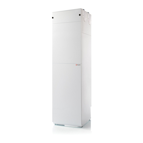
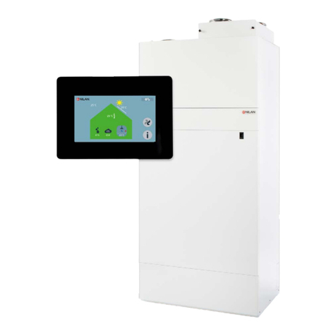
nilan Compact S CTS 602 User manual

USER MANUAL
CTS602 BY NILAN
Comfort 200 Top (English)
Version 2.10 - 12.07.2017

TABLE OF CONTENTS
Safety
Power supply................................................................................................................................................................................................................................................................... 3
Disposal............................................................................................................................................................................................................................................................................................. 3
Ventilation system....................................................................................................................................................................................................................................................3
Quick guide
Control panel............................................................................................................................................................................................................................................................................... 4
Functions..............................................................................................................................................................................................................................................................................4
Operating mode............................................................................................................................................................................................................................................................5
Menu list .............................................................................................................................................................................................................................................................................. 6
Main menu.......................................................................................................................................................................................................................................................................... 7
Show alarms ....................................................................................................................................................................................................................................................................8
Alarm list.............................................................................................................................................................................................................................................................................. 9
Show data........................................................................................................................................................................................................................................................................11
User select .....................................................................................................................................................................................................................................................................12
User select 2 ................................................................................................................................................................................................................................................................13
Setting clock................................................................................................................................................................................................................................................................. 14
Weekly programme.............................................................................................................................................................................................................................................. 15
Week program............................................................................................................................................................................................................................................................ 16
Heating surface.........................................................................................................................................................................................................................................................17
Bypass operation ...................................................................................................................................................................................................................................................18
Humidity............................................................................................................................................................................................................................................................................19
CO2..........................................................................................................................................................................................................................................................................................20
Air change....................................................................................................................................................................................................................................................................... 21
Air filter ............................................................................................................................................................................................................................................................................ 22
Temp. control ............................................................................................................................................................................................................................................................. 23
Setting language......................................................................................................................................................................................................................................................24
General information
Unit type....................................................................................................................................................................................................................................................................................... 25
Product description..............................................................................................................................................................................................................................................25
Operation and maintenance
Bypass function........................................................................................................................................................................................................................................................ 26
Humidity control...................................................................................................................................................................................................................................................... 26
Maintenance ............................................................................................................................................................................................................................................................... 27
Water trap....................................................................................................................................................................................................................................................................... 27
Filter replacement................................................................................................................................................................................................................................................. 27
Illustration of filter change.......................................................................................................................................................................................................................... 28
Heat exchanger......................................................................................................................................................................................................................................................... 29
Product data
Declaration of compliance............................................................................................................................................................................................................................ 30
Ecodesign data Comfort 200 Top..........................................................................................................................................................................................................31
2
Safety
Power supply
CAUTION
Always disconnect mains electricity to the unit if a fault occurs which cannot be rectified via the
control panel.
CAUTION
If a fault occurs on the electricity-conducting elements of the unit, always contact an
authorised electrical installer to rectify the fault.
CAUTION
Always disconnect mains electricity to the unit before opening the doors, e.g. for installation,
inspection, cleaning and filter change.
Disposal
Ventilation system
Nilan units mainly consist of recyclable materials. They should therefore not be
disposed of with household refuse. Take them to your local recycling centre.
Comfort 200 Top (English) BY NILAN
3

Quick guide
Control panel
Functions
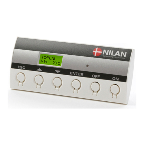
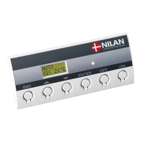
The CTS602 control panel offers the following functions:
1. Light diode Constant yellow
light:
Flashing yellow
light:
The bypass damper is open
The unit is in alarm mode
2. Text field Text is shown on 2 lines, each of 8 characters.
The upper line shows a help text.
The lower line shows the related setting values for the help text.
3. ESC To go to the main menu
4. ▲ To change the value
5. ▼ To change the value
6. ENTER To activate and save the chosen value
7. OFF To switch off the unit
8. ON To switch on the unit
If no button is pressed for a period of a minute, the control system will automatically return to the main
menu.
If you are programming when the control system returns to the main menu, all data will be saved, but
only if you previously have saved them by pressing ENTER. Flashing values and text will NOT be saved.
It is always possible to go back to your programming and resume from where you left off.
4

Operating mode
AUTO */1/L
>2< 19°C
4
21
3
The display on the control panel provides information about the unit operation:
1. Shows the operating mode: Auto / Heating / Cooling
2. Shows: * = User option active
1-2-3 = Weekly programme active
L =Low-level operation active (humidity low)
3. Shows the set fan speed.
4. Shows the desired room temperature (not actual room temperature)
The desired room temperature can be changed by pressing ENTER once. The figure next to °C will flash,
and the temperature can be now be changed using ▲▼. The desired temperature must be confirmed by
pressing ENTER
The operating mode can be changed by double-pressing ENTER. The current mode will flash and can
now be changed using ▲▼ and confirmed with ENTER. In Auto mode, the bypass damper opens and
closes automatically, depending on temperature settings. Cooling indicates that the bypass damper
will open and heating indicates that the bypass damper is closed.
The fan speed can be changed by pressing ENTER three times. The current fan speed will flash and can
now be changed using ▲▼ and confirmed with ENTER.
Comfort 200 Top (English) BY NILAN
5

Menu list
SHOW
ALARMS
AUTO W/ 1
>2< 19°C
16.05.06
TM 12:10
WEEK
PROGRAM
HEATING
SURFACE
COOLING
HUMIDITY
CO2
AIR
EXCHANGE
AIR
FILTER
TEMP.
CONTROL
LANGUAGE
ENGLISH
SHOW
DATA
USER
SELECT
USER
SELECT 2
Displaying and resetting alarms. Alarm log with the latest 16 alarms.
Operating mode (heating, auto, cooling), temperatures, fan speed and software
version.
Main menu: Shows operating status. Press ESC to return to the main menu.
Select: Extraction, intake, ventilation and OFF. The function selected is activated
via switch or button. (See assembly instructions)
Same function as User selection. The menu is accessible when the option is
selected. (See assembly instructions)
Setting clock. If the unit has no power for more than 24 hours, the clock must be
set. Switch between summer and winter time manually.
Week program can be activated. ON/OFF If the week program is active "1, 2 or 3”
are shown in the main menu.
If the unit is selected with heater. Heater can be selected ON/OFF. Frost
prevention remains active in OFF.
Setting intake temperature for cooling via bypass damper.
Higher and/or lower fan speeds can be set in the event of high/low humidity.
Higher ventilation level can be set in the event of high CO 2 levels. Menu only
shown if CO 2 sensors are fitted.
Low ventilation level in the event of low outdoor temperature can be selected.
Default setting gives filter alarm with an interval of 90 days. Reset alarm in the
"SHOW ALARMS” menu.
Setting minimum temperatures for supply air.
Select language: English, German, French, Swedish, Danish, Norwegian, Finnish
The control unit is always in the main menu by default (menu in the heavy frame). Use ▲▼ to scroll
through the other menus.
6

Main menu
AUTO
>2<
19°C
ENTER
”AUTO”
>2<
19°C
ENTER
AUTO
”>2<”
19°C
ENTER
AUTO
>2<”
19°C”
AUTO
>2<”
19°C”
”COOL”
>2<
19°C
AUTO
”>3<”
19°C
”HEAT”
>2<
19°C
2
1
3
4
1. "AUTO" >2< 19°C The unit automatically selects cooling or heating mode in relation to the
room temperature set.
2. "COOL" >2< 19°C Shows the ventilation level given that can be changed.
3. "HEAT" >2< 19°C No cooling - i.e. no bypass open.
4. AUTO ">2<" 19°C No heating from e.g. comfort heater.
The main menu will be displayed automatically approx 15 seconds after power has been connected.
Menu points flashing are shown by " ".
Comfort 200 Top (English) BY NILAN
7

Show alarms
AUTO
>2<
19°C
ENTER
16-05-06
FR 11:32
ENTER
00-00-00
FR 00:00
ENTER
ENTER ENTER
ALARM 71
DEFROST
SHOW
ALARMS
ALARM 19
FILTER
ALARM 7
FROST
ALARMLOG AL 1: 71
DEFROST
AL 2: 19
FILTER
AL 3: 7
FROST
16-05-06
FR 11:32
STATUS
ALARM
T1 20°C
T2 20°C
OUT 1-8
00000000
OUT 9-16
00000000
OUT 17-24
00000000
T3 0,00
T4 0,00
2
1
3
4
1. Alarm reset Alarms can be reset individually (inactive alarms only). When the display
shows ”Alarm 0 None” all alarms have been reset.
2. ALARM 19 FILTER Shows from 0-3 active alarms. The newest and most critical alarms are shown
first. The list will be deleted in the event of power outage.
3. ALARM LOG Restored after power outage. Shows the 16 most recent alarms. AL 1 is the
newest.
4. T3 0.00 T4 0.00 Alarm log data shows data from the time of the alarm.
When the unit is in alarm mode, the yellow diode on the CTS 602 control panel will flash.
The SHOW ALARMS menu shows the unit's alarm status and the time of the alarm. Alarms can also be
reset in this menu.
8

Alarm list
Alarm codes are given as a result of a fault or when important information should be provided to the
user.
Alarms fall into the following categories:
C Critical: Running or partially stopped as long as the alarm is active.
W Warning: Becomes critical if the situation is not improved within a reasonable period.
I Informative: Normal operation not affected. The alarm will disappear when the user cancels it.
Alarm code Category Display text Description/cause Fault correction
0 -- -- No alarm
1 C HARDWARE Fault in control system hardware Contact service if cancellation
does not help
2 C TIMEOUT Warning alarm (W) has become a
critical alarm
Note alarm and reset.
Contact service if alarm does not
disappear
3 C FIRE Fire thermostat. Units stopped
because fire thermostat is active
If there has been no fire, contact
service
7 C FROST
1. Frost protection of heater:
Intake air passing over heater
is too cold. Can be due to
bypass damper being open.
2. District/central heating water
too cold (e.g. oil-fired boiler
stopped)
1. Close bypass damper, activate
heater, reset alarm.
2. Check heating supply to
comfort heater is OK.
Reset alarm when fault
corrected.
8C Tx SHORT One of the temperature sensors
has short-circuited or is faulty
Note which sensor, Tx , has short-
circuited, e.g. T1 short and contact
service
9 C Tx OPEN One of the temperature sensors
has been disrupted or is faulty
Note which sensor, Tx , has been
disrupted, e.g. T1 disrupt and
contact service
10 C OVERHEAT
Electrical heater overheated.
Insufficient air flow due to e.g.
blocked filters, blocked air intake
or faulty intake fan
Check air is being blown into the
home.
Check filter and air intake.
Reset alarm.
Contact service if the above does
not help
11 C AIRFLOW Insufficient airflow at intake.
See alarm code 10. See alarm code 10.
15 W ROOM LOW
When the room temperature is
under 10°C the unit will stop to
avoid further cooling. This can be
for a period when the house is
unoccupied and the heating is
switched off.
Heat up the house and reset alarm
16 I SOFTWARE Fault in control system program Contact service
17 I WATCHDOG Fault in control system program Contact service
Comfort 200 Top (English) BY NILAN
9

Alarm code Category Display text Description/cause Fault correction
18 I SET
Part of the program setup lost.
Can be due to long-term power
outage or lightning strike.
The unit will continue to run on
standard setup
Reset alarm.
Program week program as
required.
Contact service if the unit is
running unsatisfactorily or as
before, as any sub-programs can
be lost. (sub-programs are only
accessible by service)
19 I FILTER
Filter sensor set for X days for
check/replacement of filter (30,
90, 180, 360 days). Standard
setup is 90 days
Clean/replace filter.
Reset alarm.
21 I SET TIME Occurs in the event of power
outage
Week timer settings must be
checked and set if required.
Reset alarm.
22 I T AIR
Target heating of intake air not
possible (only applies if comfort
heater fitted). Comfort heater and
unit cannot raise the temperature
to target.
Set lower target intake
temperature.
Reset alarm.
71 W EXCH DEF
Max. defrosting time exceeded for
counterflow exchanger. Can be
because the unit has been exposed
to low temperatures
Contact service if cancellation of
alarm does not help. Note current
operating temperatures from the
SHOW DATA menu as an aid to
service
91 I OPT IO Option PCB missing Contact service
92 PRESET Error when entering or loading
installer's settings Contact service
10

Show data
STAUS
HEATING
BYPASS
CLOSED
PANEL
T15 20°C
EXSTERNAL
T10 21°C
HUMIDITY
100%
CO2
566ppm
INLET
T2 21°C
EXHAUST
T3 22°C
FRESHAIR
T8 15°C
OUTLET
T4 13°C
INLET
FLOW 2
WATER
T9 8°C
EXHAUST
FLOW 2
SOFTWARE
1 2.33
SOFTWARE
2 1.04
TYPE
COMFORT
ENTER
SHOW DATA
1
2
3
4
57
6
8
1. PANEL T15 20°C Room temperature measured at T15 (sensor in CTS602 panel)
2. EXTERNAL T10 21°C T10 is an external sensor that can be fitted in an extraction fitting in the
accommodation zone. T10 can be selected as the governing room sensor in
the service menu (See assembly guide).
3. CO2566ppm In units with CO2sensor, CO2concentration is shown.
4. INLET T2 21°C T2 will show on units with no heater. T7 will show on units with heater.
5. EXHAUST T3 22°C Sensor in extraction air. T3 can be selected as the governing room sensor in
the service menu (See assembly guide).
6. WATER T9 8°C T9 will show on units with water heater.
7. SOFTWARE 1 2.33 Software version installed on the unit.
8. SOFTWARE 2 1.04 Software version installed on control panel.
Actual operating data can be read off under the SHOW DATA menu.
Comfort 200 Top (English) BY NILAN
11

User select
ENTER
ENTER
ENTER
ENTER
SELECT
EXTEND
TIME
00:00
FLOW
>4<
TEMP
23°C
TIME
”00:00”
FLOW
”>4<”
TEMP
”23°C”
ENTER ENTER
SELECT
”EXHAUST”
SELECT
”VENTILAT”
SELECT
”C HOOD”
ENTER
ENTER
ENTER
SELECT
”OFF”
SELECT
”EXTEND”
USER
SELECT
ENTER
1
2
3
SELECT
”INLET”
5
6
4
7
1. TIME 00:00 Required period in which the selected function is to remain
operative, started in hours and minutes. Max. 8 hours.
2. FLOW <4> Required ventilation level : 1-4. OFF allows the system to be shut
down via an external switch.
3. TEMP 23°C Required room temperature (5-30°C). Panel sensor T15 is the
controlling sensor.
4. SELECT "INTAKE" "EXHAUST" Time and speed must be set in the same way, as described under
SELECT EXTEND.
5. SELECT "VENTILAT" Possibility to run a higher or lower spped. High priority.
6. SELECT "C HOOD" RE1: Close switch for controlling of hood damper motor.
7. SELECT "OFF" User selection deactivated.
The menu USER SELECT overrides the operating mode of the main menu by activating an external
switch.
12

User select 2
ENTER
ENTER
ENTER
ENTER
SELECT
EXTEND
TIME
00:00
FLOW
>4<
TEMP
23°C
TIME
”00:00”
FLOW
”>4<”
TEMP
”23°C”
ENTER ENTER
SELECT
”EXHAUST”
SELECT
”EXT OFFS”
SELECT
”VENTILAT”
SELECT
”C HOOD”
ENTER
ENTER
ENTER
SELECT
”OFF”
SELECT
”EXTEND”
USER
SELECT 2
ENTER
ENTER
1
2
3
SELECT
”INLET”
5
7
6
4
8
1. TIME 00:00 Required period in which the selected function is to remain
operative, started in hours and minutes. Max. 8 hours.
2. FLOW <4> Required ventilation level : 1-4. OFF allows the system to be shut
down via an external switch.
3. TEMP 23°C Required room temperature (5-30°C). Panel sensor T15 is the
controlling sensor.
4. SELECT "INTAKE" "EXHAUST" Time and speed must be set in the same way, as described under
SELECT EXTEND.
5. SELECT "EX OFFS" Option for relay output R8, if fitted. Only possible on a
supplementary PCB. The temperature is added or subtracted to/
from the set point. Choose the afterrunning and displacement of
the set point for external room heating. Selected in the same way
as shown under SELECT EXTEND .
6. SELECT "VENTILAT" Possibility to run a higher or lower spped. High priority.
7. SELECT "C HOOD" RE7: Close switch for controlling of hood damper motor.
8. SELECT "OFF" User selection deactivated.
The USER SELECT 2 menu is used as USER SELECT . (only shown when option PCB is fitted)
Comfort 200 Top (English) BY NILAN
13

Setting clock
WEEK
DAY 6
HOUR
12
MINUTE
10
HOUR
”12”
MINUTE
”10”
ENTER
ENTER
ENTER
1
2
YEAR
16
MONTH
05
DAY
07
YEAR
”16”
MONTH
”05”
DAY
”07”
ENTER ENTER
ENTER
ENTER
ENTER
ENTER
ENTER
ENTER
16-05-06
FR 12.10
1. WEEK DAY 6 Shown first time only after setting up timer function, Monday = 1.
2. MINUTE "10" Seconds are reset when the minute value is adjusted.
In the event of power outage the clock will work for at least 24 hours. If the time function is lost, an
alarm will show: "SET TIME".
Switch between summer and winter time manually.
Menu points flashing are shown by " ".
14

Weekly programme
MO 1 08.00
>1< 17°C
5
321
4
1. Mo Day of week.
2. 1 Function step. There are 6 function steps for each day.
3. 08.00 Time for activation of function step.
4. >1< Fan speed.
5. 17 °C Selected temperature.
The unit has 3 weekly programmes. The unit's default setting is OFF.
There is also an option for programming your own weekly programme. This could be one of the
standard programmes, but with small changes.
Flashing menu items are designated with " ".
Default setting for the 3 weekly programmes:
• Programme 1 is for working families.
• Programme 2 is for stay-at-home families.
• Programme 3 is for businesses.
Programme Day of week Function Time Fan speed Temperature °C
Programme 1 Monday - Friday
1
2
3
4
6.00
8.00
15.00
22.00
3
1
3
1
21
21
21
21
Saturday - Sunday 1
2
8.00
23.00
3
1
21
21
Programme 2 Monday - Sunday 1
2
8.00
23.00
3
1
21
21
Programme 3 Monday - Friday 1
2
7.00
16.00
3
OFF
21
21
Comfort 200 Top (English) BY NILAN
15

Week program
ENTER
ENTER
ENTER
ENTER
SELECT
”OFF”
MO 1 06.00
>3 < 21°C
MO 2 08.00
>1 <17°C
MO 3 OFF
>1 <17°C
MO 4-6
MO ------> TU
COPY
TU 1 06.00
>3 <21°C
TU 2-6
SELECT
”PROG2”
SELECT
”PROG3”
SELECT
”CLEAR”
SELECT
OFF
ENTER ENTER
ENTER
TU ------> WE
COPY
MO ------> TU
”COPY”
ENTER ENTER
WEEK
PROGRAM
1
4
3
5 5 5
ENTER
ENTER
ENTER
SELECT
”PROG1”
SELECT
PROG1
2
1. SELECT OFF Unit mode with regard to main menu.
2. SELECT "PROG1-2-3" 1 of 3 week programs can be selected here. A week program can be
selected as active and customised to the user's requirements.
3. SELECT "CLEAR" All functions in the program selected are set to OFF here. The unit
will continue in AUTO mode with active week program.
4. MO 1 06.00 >3< 21°C A custom week program can be composed here, or the values of
another program revised. If several functions are coded in at the
same time, only the last/lowest function will be activated.
5. MO---> TU/WE COPY When values have been entered for the Monday program, it can be
copied to the other days with the same requirement via the Copy
function.
16

Heating surface
2
SELECT
ON
SELECT
”ON”
SELECT
”OFF”
ENTER ENTER ENTER
ENTER
HEATING
SURFACE
1
1. SELECT "ON" When a comfort heater is fitted, the intake sensor, T2, is transferred
automatically to T7 mounted in the intake after heater.
1. SELECT "OFF" If supplementary heating from the comfort heater is to be disconnected, select
this position.
Frost protection is still active and T7 is the sensor for intake air.
The HEATING SURFACE menu is only accessible if the unit is fitted with an external comfort heater and
the control system has been set up for comfort heater in the SERVICE menu.
Menu points flashing are shown by " ".
Comfort 200 Top (English) BY NILAN
17

Bypass operation
AUTO
>2<
19°C
ENTER
VENTILAT
HIGH ”2”
ENTER ENTER
VENTILAT
HIGH 2
COOLING
1
1. VENTILAT HIGH "2" Select between levels 2, 3, 4 and OFF.
The COOLING menu allows selection of the unit automatically running at a higher/highest ventilation
level for low bypass mode.
Bypass operation is used when there is no need for heat recovery.
18

Humidity
TIME
60 MIN
ENTER
4
HUMIDITY
LOW >1<
LOW
30%
HUMIDITY
HIGH >4<
HUMIDITY
LOW >”1”<
LOW
”30%”
HUMIDITY
HIGH >”4”<
ENTER ENTER
ENTER
ENTER
ENTER
TIME
”60” MIN
ENTER
ENTER
ENTER
HUMIDITY
1
2
3
1. HUMIDITY LOW "1" Option for selecting lower fan speed in case of low air humidity.
The value can be set to: OFF and 1, 2, 3.
2. LOW "30"% Range adjustable between 15-45%. 30% is standard
3. HUMIDITY HIGH "4" Option for selecting higher fan speed in case of high air humidity.
The value can be set to: OFF and 2, 3, 4.
4. TIME "60" MIN Maximum duration of high fan speed due to high air humidity.
The time can be set from 0-180 min.
The HUMIDITY menu has a option for running at higher and/or lower fan speeds in case of high/low air
humidity.
Low fan speeds are only activated in winter operation and at air humidity levels below 30%.
High speeds are activated by a change from 10% to 5% compared to an average relative air humidity of
40% to 80% over the last 24 hours.
When the current air humidity decreases to the average relative air humidity + 3%, high speed
operation will end. If the time expires before the air humidity has reached this level, high speed
operation will end.
High fan speed is deactivated again when the air humidity falls to within 3% or less of the 24 hour
average.
Up to 3 minutes may elapse before the high/low fan speed has stabilised.
Flashing menu items are designated with " ".
Comfort 200 Top (English) BY NILAN
19

CO2
NORMAL
600ppm
3
2
FLOW
HIGH 3
HIGH
800ppm
FLOW
HIGH ”3”
HIGH
”800”ppm
ENTER ENTER
ENTER
ENTER
NORMAL
”600”ppm
ENTER
ENTER
ENTER
CO2
1
1. FLOW HIGH "3" Option for selecting high fan speed in case of high CO2concentration. The
value can be set to: OFF and 2, 3, 4.
2. HIGH "800" ppm Limit for maximum CO2concentration before operation at high fan speed
begins. (400-2500 ppm)
3. NORMAL "600" ppm Limit for minimum CO2concentration before operation at normal fan speed
begins. (400-2500 ppm)
This menu is only available if CO2sensors have been mounted on the unit. CO2sensors are optional
equipment, NOT supplied together with the Comfort range.
The CO2menu contains an option for selecting whether the unit will automatically run at the higher fan
speed in the case of high CO2levels.
Flashing menu items are designated with " ".
20
Other manuals for Compact S CTS 602
11
Table of contents
Other nilan Control Panel manuals

nilan
nilan Compact S CTS 602 User manual

nilan
nilan CTS 150 User manual

nilan
nilan CTS 600 User manual

nilan
nilan CTS 600 User manual

nilan
nilan comfort CT150 User manual

nilan
nilan CTS6000 User manual

nilan
nilan Compact S CTS 602 User manual

nilan
nilan CTS 602 User manual

nilan
nilan CTS6000 User manual

nilan
nilan CTS700-TOUCH Compact P GEO Mounting instructions
Popular Control Panel manuals by other brands

Pulsar
Pulsar 17/TRP50/DSPR Assembly instruction

Eurofours
Eurofours E-Drive Programming instructions

BFT
BFT SHYRA AC SL installation manual

Clarion
Clarion CMRC1-BSS Owner's manual & installation guide

Bentel Security
Bentel Security FireClass 200 installation manual

AERMEC
AERMEC MVASZC User & installation manual