Nitta NITTAOMEGA type M165-K User manual

1~7【日本語】
取付ガイド
9~15【English】
Installation Guide
17~23【中文】
安装说明书
オートマチックツールチェンジャー取り付け注意事項
1
●本書での表示
オートマチックツールチェンジャー : 以下ATCとする
この表示を無視して誤った取り扱いをすると、使用者が死亡又は、重症を負う切迫した
可能性があることを示しています。
この表示を無視して誤った取り扱いをすると、使用者が死亡又は、
重症を負う可能性があることを示しています。
この表示を無視して誤った取り扱いをすると、使用者が障害を負う、可能性があることを示しています。
又、物的損害が発生する危険性が有ることも表しています。
ATC(アダプタ、モジュール)は単体で作業できるものでなく、ロボットおよび、専用機に取り付けて初めて作業可能になります。
安全性を考える場合、ATC単体のみならず、ロボットシステム、専用機システム全体として考慮していただく必要があります。
●準備
ATCのご使用にあたっては、中心となるロボット、専用機についての安全指示を厳守いただきますようお願い申し
上げます。ロボット安全柵内での作業を行う場合は、柵内に入ると同時に50Vを超える電力が遮断されるよう、安
全システム設計を考慮ください。
安全柵内で作業を行う場合は、ヘルメット、安全靴、保護具などの安全器具を身につけて作業内容に適した作業服
を着用ください。ATCの内部分解作業では、部品の飛び出し保護のため、保護めがねの着用をお願いします。
ATCについてのロボット安全柵内で取り付け、プログラミング作業、保守点検業務に従事いただく皆様は、ロボット
の専門知識を習得(専門教育受講者)いただく必要があります。加えて、安全柵内、外を問わず、ATCについて分
解、組立作業に従事される方は、本書と取扱説明書を熟読いただく必要があります。
1
●作業時
Automatic Tool Changer
NITTAOMEGA type M165-K
取付作業に入る前に以下の注意点を必ず実行してください。
a) 作業をおこなう際は全ての溶接電源、制御電源,動力電源を切ってあること。
b) 作業をおこなう際は全ての空圧が止めてあること。
c) 作業をおこなう際は全ての空圧の残圧が抜いてあること。
d) コネクタ、ケーブルの一部は仕様により熱を発生しますので注意してください。
取付作業中に、作業者に無断で電源,空圧が投入されると、極めて危険な状態が起こる可能性があります。
このようなことを絶対に起こさないシステムを設けて、安全に作業ができるようにしてください。

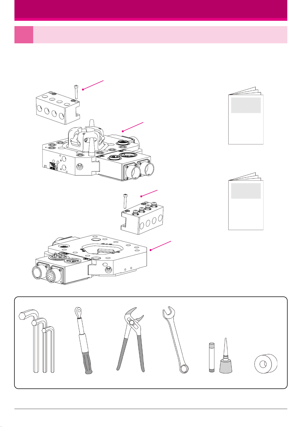
●お客様ご自身でご用意いただくもの
《梱包内容物》
2
※上記は標準的な構成です。ロボットアダプタプレート、ツールアダプタプレート、絶縁材、フィッティング、ケーブル等はお客様が用意する
場合と弊社が用意する場合があります。構成の詳細は納入仕様書をご参照ください。
ロボット側各モジュール+取付ボルト
ロボットアダプタ+取付ボルト
ツール側各モジュール+取付ボルト
ツールアダプタ+取付ボルト
取扱説明書
ATC取付ガイド(本書)
六角レンチ トルクレンチ プライヤー スパナ ねじ緩み止め シールテープ
取り付け準備をする
2
オートマチックツールチェンジャー 取付ガイド
※本製品に関する詳細な情報は
取扱説明書をご参照ください。
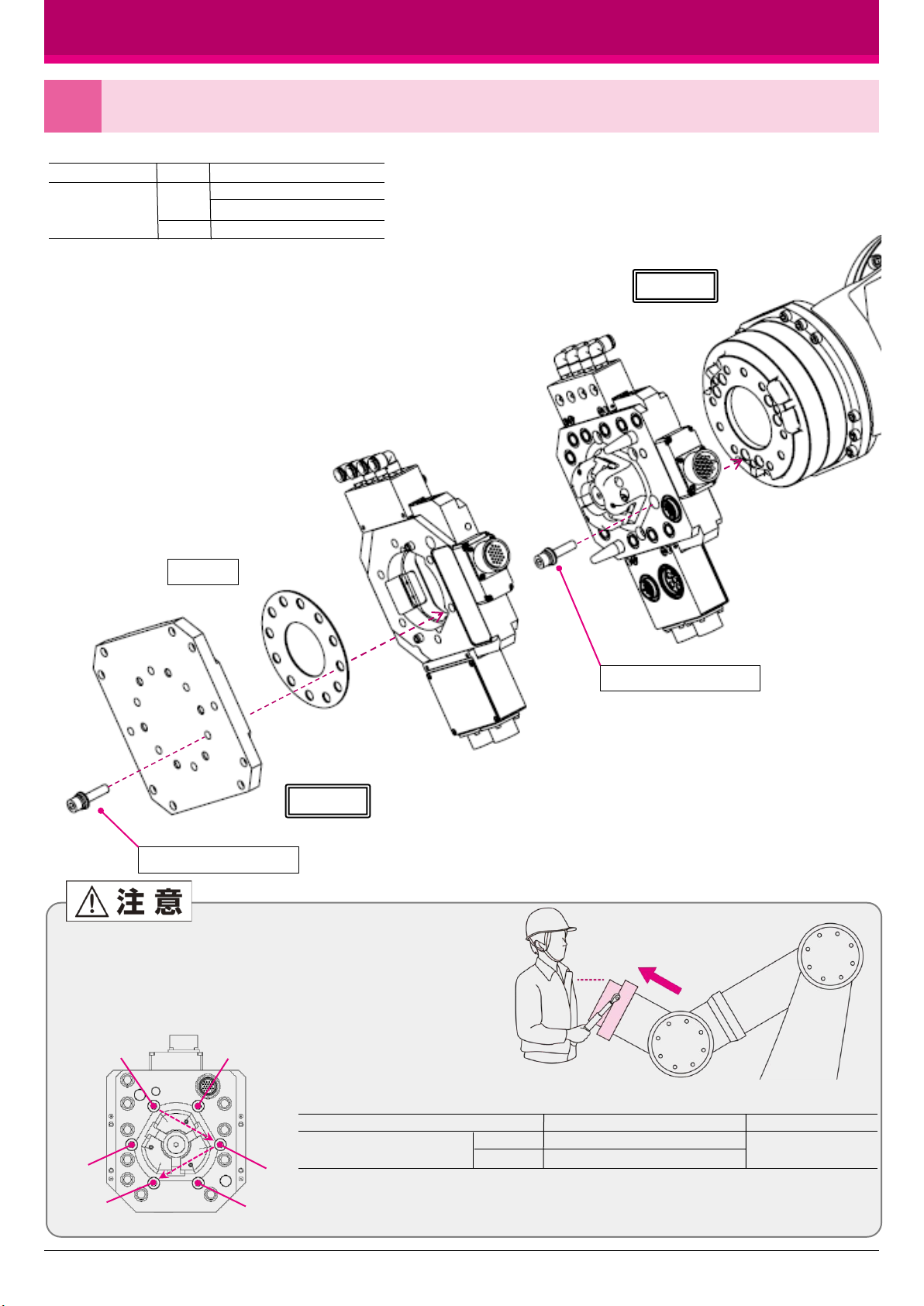
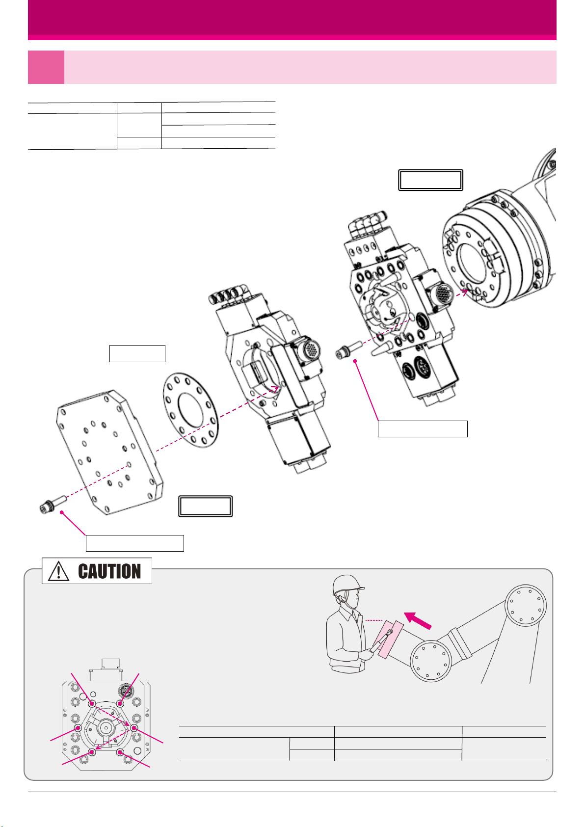
ATCをロボットに取り付ける(例)
3
3
各ボルトを番号順に複数回にわけて
締付け、各ボルトに均一な力がかか
るようにしてください。
例:①→②→③→……のように対角で
締めていく。
取付作業はATCの落下を防ぐため
にロボットフランジ面を上向きにして
胸の高さに合わせて行ってください。
※絶縁材の取付方法はお客様により異なります。
ロボット側に取り付ける場合もあります。
オートマチックツールチェンジャー 取付ガイド
M5 ×35 SCM (各2本)
モジュール種類
信号モジュール
サーボモジュール
給気モジュール
項目 ロボット側 ・ツール側共通
ネジ形状
トルク 5Nm
M5ショルダーボルト SCM (各2本)
※ボルトにはねじ緩み止め剤(低強度)を塗布して使用してください。
M10 (6本)、SW
絶縁材※
M10 (6本)、SW
①
②
③
④
⑤
⑥
アダプタの組み付けボルト一覧表
機種 取付ボルトサイズ トルク値
R側
T側
M10(SW併用)
M10(SW併用) 60Nm
※ボルトにはネジ緩み止め(低強度)を塗布してください。
NITTAOMEGA type M165-K
ロボット側
ツール側

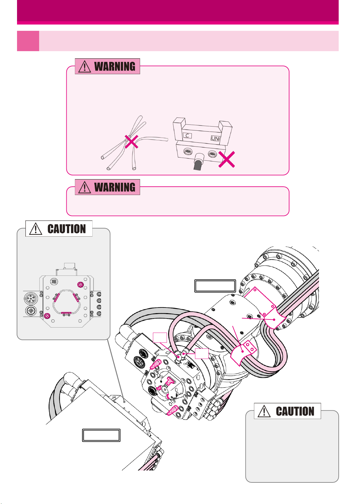
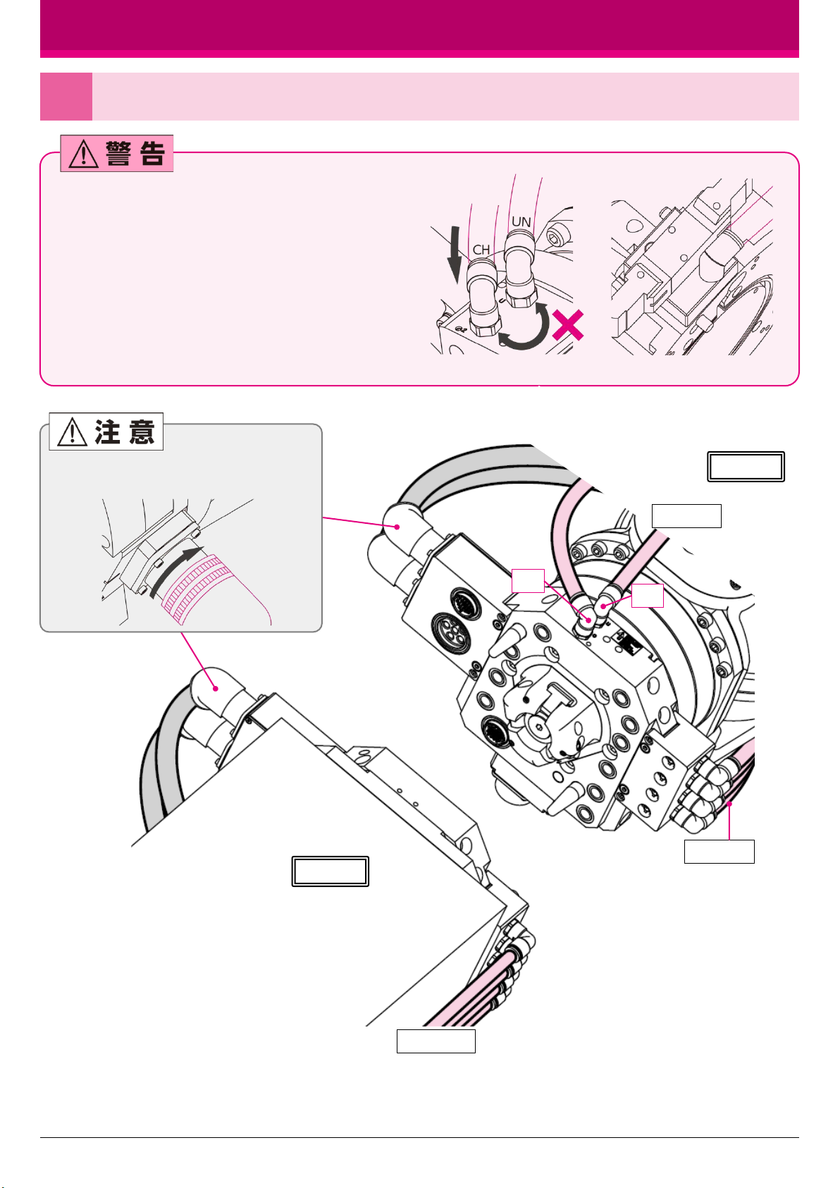
ケーブル、ホース・チューブ類を接続する
4
オートマチックツールチェンジャー 取付ガイド
4
必ず各電源、エア等をOFFにして作業を開始してください。
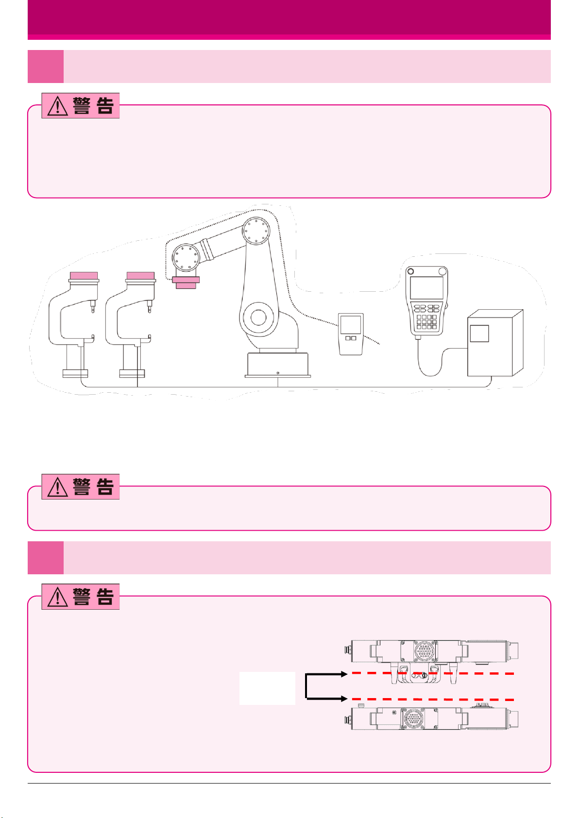
●チャック(CH)・アンチャック(UN)の配管時チューブを差し間違えないで
ください。ツールを落下させる恐れがあります。
●マーカー等でチャック(CH)のチューブ、アンチャック(UN)のチューブを
明示してください。
●チューブ類は抜けないように奥まで確実に差し込んでください。
●チャック・アンチャックのエアー配管は、標準仕様と電磁弁仕様
(電磁弁付きロボットアダプタ)の2種類があります。
●電磁弁仕様は、エアー供給口が1箇所となります。
●エアーの手動切り替えは、不用意に行わないでください。
電磁弁仕様はチューブ1箇所
標準仕様 電磁弁仕様
ツール側
CH
ホース・チューブ類
ホース・チューブ類
UN
ロボット側
ホース・チューブ類
ロボット動作時にコネクタが外れないように
最後まで確実に締めてください。

ロボット側
ツール側
①
CH
UN
ティーチング前(ロボット稼働前)に確認すること
5
オートマチックツールチェンジャー 取付ガイド
5
アンチャックチューブの折れ、ねじれや
結束バンドの締め過ぎでエアが遮断さ
れないようにしてください。エアが遮断さ
れるとカムが正常に動作できず、ツー
ル側が落下する恐れがあります。
連結時にアンチャックポートのエアが排気されて
いることを確認してください(残圧無きこと)。残圧
により、カムが正常に動作できず、ツール側が落
下する恐れがあります。
ツール側
マニホールドや電磁
弁の排気ポートを埋
め栓等でふさがない
でください。
ツールを連結しロボットを動作する際は、必ずチャックポートにエアーを供給してください。
網掛けの箇所にグリスが塗布され
ていることを確認してください。
ケーブル、ホース・チューブ類(以
下ケーブル類)をブラケット等に固
定し、切断、破損が無いように取回
してください。またロボット動作時に
周辺機器やワーク等に干渉しない
ようにケーブル類を固定してくださ
い。※イラスト①
インターロックを確認する
6
オートマチックツールチェンジャー 取付ガイド
6
ATCのチャック(※1)、アンチャック(※2)、フェイス(※3)、及びツール在席信号等のインターロックの設定を行ってください。インターロック
信号がPLCなどの上位の制御機器に入力されていることを確認してください。インターロック信号の設定を行っていないと誤操作・誤動作に
より、安全が確保されずツールを落下させる可能性があります。
※1チャック:カムが開いている状態を示す信号 ※2アンチャック:カムが閉じている状態を示す信号
※3フェイス:ロボットアダプタとツールアダプタの互いの連結面が密着している状態を示す信号
①ツール在席の確認
②各ツールNO.識別の確認
③ATC内部信号の確認(フェイス、チャック、アンチャック)
④ATC駆動用エア圧低下の検知確認
●上記イラストはインターロックの一例です。お客様の設備に応じて安全なインターロックをご設計ください。
●弊社には、落下防止メカバルブおよび安全スイッチ仕様があります。(弊社にご相談をお願いします)
●落下防止メカバルブや安全スイッチ仕様をご使用なさらない場合は、お客様にて必ず他の安全システムの設置を行なって頂けるようお願いします。
着脱用電磁弁は連続信号を推奨します。ワンショット信号はお止めください。ワンショット信号の場合はノイズ等による誤動作の為に連結
状態を維持できず落下する可能性があります。
ティーチング時に確認すること
7
ATC着脱動作中にはロボットアダプタとツールア
ダプタの両方の連結面が平行であることが必要で
す。平行度が維持できないと、正確な連結ができ
ないことやスムーズな分離ができないことがあり
ます。
又、電気接点、給水・給気ポートの早期破損の可
能性があります。ロボットや置き台で平行度が維
持できない場合は、置き台にコンプライアンスをも
たしていただく必要があります。コンプライアンス
を持った置き台では、ロボットでロボットアダプタを
ツールアダプタに押し付けることにより、連結面を
密着させるようにしてティーチングしてください。
NO.1 NO.2
エア圧検知器
平行を
維持する

ライン停止時(又はライン稼働時)に確認すること
8
オートマチックツールチェンジャー 取付ガイド
7
●推奨する使用方法
夜間、休日などロボットを稼働しないときは、ツール側を分離してください。
稼働時はツール側を連結するためのアプローチの際、カムが閉じているこ
とを確認してください。カムが開いたままで連結動作を行うとカムとロックピ
ンが衝突し破損する可能性があります。
●推奨しない使用方法(設備の都合上やむを得ない場合)
設備停止時、ツール側を分離することが設備の都合上不可能である場合、
下記を十分留意ください。
ツール側を連結したままラインが停止するときは、エア元圧の有無に関わ
らずアンチャックポートは大気開放してください。(残圧無きこと)
アンチャックポートが開放されていないとエアの回り込みなどでカムが動作
し、ツール側が落下する恐れがあります。設備停止をする前にツールが落
下しない姿勢にして電源・AIRをOFFにしてください。
ROBOT POWER OFF
搬送時の注意事項
9
エアを供給しないまま連結した状態で運搬する際は、ロープ等を用いて
ツール側が落下しないようにしてください。 ロープ等で
固定する
<アンチャックポートにエア残圧がある事例>
●アンチャックチューブの折れ、ねじれや結束バンドの締め
過ぎによりエア遮断が起きた場合(5頁参照)
●マニホールドや電磁弁の排気ポートが埋め栓等でふさが
れている場合(5頁参照)等
ライン再稼働前に確認すること
●連結面に隙間無きことをご確認ください。
ROBOT POWER OFF
AIR ON
ROBOT POWER OFF
NG 推奨はしないが
やむ得ない場合
アンチャックポート
大気開放
可能な限り、ツールを
低位置に移動する
アンチャックポート
大気開放

Installation Guide
Precautions for Installation of Automatic Tool Changer
1
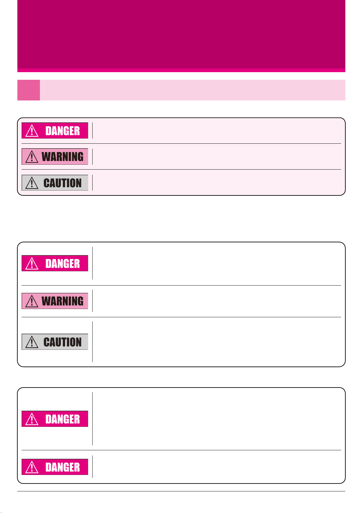
●Indications in this document
Automatic tool changer is hereinafter abbreviated as "ATC."
Improper use disregarding this indication may result in imminent risk of death or serious injury
of the user(s).
Improper use disregarding this indication may result in risk of death or serious injury
of the user(s).
Improper use disregarding this indication may result in risk of injury of the user(s) leading
to disabilities, or property damages.
ATC (adaptor and module) does not work alone and is only usable when being equipped on a robot and a compatible unit. For
increased safety of the entire system, it is necessary to consider not only the single ATC but also the robot system and
compatible unit system as a whole.
●Preparation
For use of ATC, be sure to observe safety instructions concerning core robots and
compatible units. For any work within the robot safety fence, consider preparing a safety
system design that shuts down power over 50Vin any event where a person gets into the
fenced area.
In addition, for works in the safety fence area, be sure to wear appropriate clothing for the
work with personal protective equipment such as a hard hat, safety boots, etc. For internal
disassembly works for the ATC, use protective glasses for protection against pop-out parts.
Personnel engaged in installation, programming and maintenance works inside the robot
safety fence for the ATC must have expertise in robot operations (having completed expert
training). Additionally, personnel engaged in disassembly and assembly works of the ATC
either in or out of the safety fence must read this document and other relevant manuals
carefully.
9
●Work
Automatic Tool Changer
NITTAOMEGA type M165-K
Be sure to check the following items before starting the installation procedure:
a) Welding power source, control power source and driving power source are all shut off before
work.
b) All pneumatic sources are off before work.
c) All residual pneumatic is released before work.
d) Note that some connectors and cables may be hot depending on their specifications.
Turning the power supply or pneumatic source ON during the installation work without notifying
the operator(s) may create an extremely dangerous situation. Establish a procedure to always
prevent such events for safety in work areas.
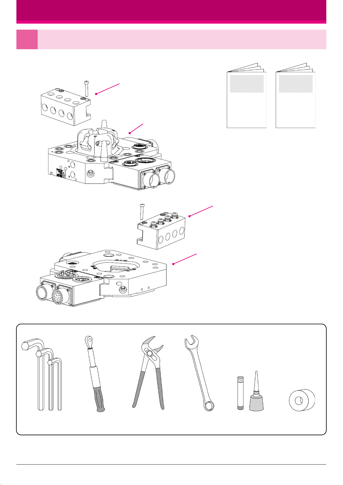
●Items to be prepared by customer
《Package components 》
10
※ The above is the standard configuration for your reference. The robot adaptor plate , tool adaptor plate, insulator, fittin gs,
and cables, etc.may be prepared by customer depending on conditions. For details of your configuration,
please refer to respective delivery specifications.
Robot side modules + mounting bolts
Robot adaptor + mounting bolts
Tool side modules + mounting bolts
Tool adaptor + mounting bolts
Instruction
MANUAL
Hex wrench Torque wrench Plier Spanner wrench Screw locking
agent
Sealing tape
Preparing for installation
2
Automatic Tool Changer Installation Guide
ATC Installation
Guide
※Please refer the instruction manual about
products more details.
Robot side
Tool side
Installing ATC to a robot (example)
3
11
Automatic Tool Changer Installation Guide
Tighten bolts in the order of the
numbers in steps so that equal
force is applied to each bolt.
Ex:Tightening screws in a criss-
cross pattern starting with (1), (2),
(3) and so on.
For the installation work, set
the robot flange surface facing
upward at the height of your
breast to prevent ATC from
falling.
Screw shape
Robot side and Tool side
List of module assembly bolts
Module types
Signal module
Servo motor module
Pneumatic module
Item
Torque
M5 ×35 SCM (2pcs)
M5 shoulder bolts SCM (2pcs)
5Nm
※Apply screw locking agent (low strength) to each bolt.
※A procedure to attach the insulator varies depending on customer conditions;
it may be attached onto the robot side in some cases.
M10 (SW)6pcs
Insulator ※
M10 (SW)6pcs
①
②
③
④
⑤
⑥
Adaptor mounting bolt correspondence table
Model Mounting bolt size Torque
R side
T side
M10(SW)
M10(SW)60Nm
※Apply screw locking agent( low strength)to each bolt.
NITTAOMEGA type M165-K

Connecting cables, hoses and tubes
4
12
Be sure to shut off the power supply and air etc.
Automatic Tool Changer Installation Guide
Single tube connection
for solenoid valve spec
Solenoid Valve equipped type
●Be sure to connect chuck (CH) and unchuck (UN) tubes
properly. Otherwise the tool side may fall off.
●Mark the chuck (CH) and unchuck (UN) tubes accordingly.
●Securely insert the tubes to the end to prevent disconnection.
●There are 2 different chuck / unchuck air piping, one is the
standard model, and the other is Solenoid volve equipped
model.
●Solenoid volve equipped model has only one single air port for
check / unchuck operation.
●Please make sure the safety when you operate chuck /
unchuck operation manually. Standard type
Tool side
CH
Hoses and tubes
Hoses and tubes
UN
ロボット側
Hoses and tubes
Securely tighten to prevent connector
disconnection during robot operations.
Robot side
Tool side
①
CH
UN
Checking before teaching (robot operations)
5
13
Check that the unchuck port air is
discharged when jointing (no residual
pressure). Any residual pressure may
prevent normal cam operations and cause
the tool side fall off.
Tool
Automatic Tool Changer Installation Guide
Route and fix the cables, hoses and
tubes (hereinafter cables, etc.) to
the bracket without breaking them.
Also, fix the cables, etc. so that they
do not interfere with peripheral
components and work pieces during
robot operations.
※Illustration ①
Ensure that air supply is not shut off
by bending/twisting of the unchuck
tube and excessive tightening of the
banding bands. When the air supply is
inhibited, the cam may not work
properly resulting in
tool side falling.
Make sure the
exhaust ports of
the manifold and
solenoid valve are
not plugged.
Please make sure to provide the air to chuck port when robot is operating with
tool side.
Ensure that grease is applied to
the shaded portions.

Interlock check
6
14
Configure interlock settings for chuck(*1), unchuck (*2), face (*3)and tool presence signals, etc. of the ATC. Check
that interlock signals are input to the superior control devices, such as PLC. If you are not set up the interlock circuit, tool
side might be dropped when it is operated in wrong way.
*1 Chuck signal: it shows cams are open. *2 Unchuck signal: It shows cams are close.
*3 Face signal:It shows Robot adaptor and tool adaptor are contacting with each other.
NO.1
①Tool presence check
②Tool NO. identification ③ATC internal signal check (face, chuck and unchuck)
④ATC drive air pressure decrease detection check
●The illustration above shows an example interlocking scheme for your reference.
Please design safe interlocking scheme appropriate for your facilities.
●We have a Fall prevention system and Safety Switch equipped ATC model. Please contact us if you are interested in.
●Please make sure to use other way of safety system even if you do not use Nitta systems.
NO.2
Air pressure
detector
Continuous signaling is recommended for solenoid valves for chuck / unchuck. Please don’t use one-shot signaling
because it may not maintain the joint due to malfunction caused by any noise resulting in tool side falling.
Check points in teaching
7
The connection surfaces of the robot adaptor and
tool adaptor must be in parallel during the ATC
chuck / unchuck operation. Otherwise, proper
jointing and smooth separation may be prevented,
and the electric contacts and water/air supply
ports may be spoiled earlier. If you cannot
maintain parallelism with the robot and its stand,
you may have to use compliance on its stands to
make an adjustment. In such cases, mate the flat
surfaces by pressing the robot adaptor against
the tool adaptor for proper teaching.
Automatic Tool Changer Installation Guide
Keep
parallel

Points to check during line downtime (or line uptime)
8
15
●Recommended usage
During the robot downtime, e.g. nighttime or holidays, keep
the tool side separated.
When you start to operate the robot approaches to the
tooling side for chucking operation, please make sure to
close the cams.
If the robot is going to chuck with the cams open, the cams
will collide with the lock pins and ATC will be damaged.
Precautions for transportation
9
To move the system with ATC jointed together without air
supply, use rope to bind them and prevent tool side from falling. Fix by rope, etc.
Automatic Tool Changer Installation Guide
●Usage not recommended
(only allowed if there is an absolute necessity)
If the tool side cannot be kept separated during downtime due to any
reasons related to the facilities, take due care of the following. If the line
has to be stopped with the tool side jointed, be sure to release the
unchuck port air regardless of air supply pressure presence. (No residual
pressure allowed.) If the unchuck port is not released, the cam may close
due to the residual air and result in tool side falling. Please move the
robot to the position where tool side cannot be dropped off before line
downtime and turn off the electricity and air pressure.
<There may be residual air pressure when>
●air exhaust is shut off by bending/twisting
of the unchuck tube or excessive tightening
of the banding bands (see page 13): or
●the exhaust ports of the manifold and
solenoid valve are plugged (see page 13).
Points to check before restarting the line
●Ensure there is no gap on the joint surface.
ROBOT POWER OFF
ROBOT POWER OFF
AIR ON
ROBOT POWER OFF
NG Not recommended way.
(Only allowed if it is necessary)
Releasing unchuck
port air
Releasing unchuck
port air
Make sure to move the
tool to lower position
as much as possible.


安装说明书
自动工具交换装置安装注意事项
1
●本说明书中的图标 自动工具交换装置:以下称为ATC
如果无视本图标、错误操作,有可能导致使用者死亡或负重伤。
如果无视本图标、错误操作,有可能导致使用者死亡或负重伤。
如果无视本图标、错误操作,有可能对使用者带来伤害。另外,也有发生物品损坏的危险性。
ATC(本体、模块)无法单独使用,需安装到机器人、专用机械上后使用。因此为了安全使用此系统,不应只考虑交换ATC单体产品,
还需要对机器人系统、专用机械系统进行全体考虑。
17
●作业时
在进入安装作业前,必须注意以下几点。
a) 进行作业前,必须切断所有焊接电源、控制电源和动力电源。
b) 进行作业前,必须停止所有气压源。
c) 进行作业前,必须去除气管中的残留压力。
d) 部分规格的接头、电缆会发热,请注意。
安装作业中,如果作业员擅自打开电源、气压源,可能引发及其危险的状态。请设计绝对不会引发这种状
态的安全作业系统,以便进行安全作业。
●准备
在使用ATC时,请严格遵守机器人、专用机械的安全指示。要进入机器人安全围栏内进行安装作业时,请
将安全系统设计为进入围栏内时切断超过50V的电源。
安全围栏内进行作业时,请装备安全帽、安全鞋、保护工具等安全器具,穿上与作业内容相符的工作服。
在ATC的内部分解作业时,为了防止部品飞出造成伤害,请戴好保护眼镜。
参与ATC在机器人围栏内安装、程序设计作业、保养点检作业的各位人员,必须是接受过机器人专业知识
培训(受过专业知识教育的人)的人员。并且,无论在围栏内或外,对ATC进行分解、组装时,必须熟读
本书和使用说明书。
自动工具交换装置 ATC
NITTAOMEGA type M165-K
●用户需要准备的物品
《包装箱内物品》
18
※上述是标准的构成。机器人本体侧连接板、工具本体侧连接板、绝缘材料、接头、电缆等有用户准备和本公司准备两种情况。
构成的详细请参照纳入仕样书。
机器人侧各模块+安装螺钉
机器人侧本体+安装螺钉
工具侧各模块+安装螺钉
工具侧本体+安装螺钉
使用说明书
ATC安装说明书
(本说明书)
内六角扳手 扭力扳手 钳子 扳手 螺纹紧固剂密封生胶带
安装准备
2
自动工具交换装置 安装说明书
※关于本产品的详细参数请
参考使用说明书

机器人侧
工具侧
※绝缘材料的安装方法因用户而异。
也有在机器人侧安装的情况。
M10(6根)、附弹垫
绝缘材料※
M10(6根)、附弹垫
把ATC 安装机器人上(例)
3
19
将各螺钉按照编号顺序分数回拧
紧,施力均等。
例:下图①→②→③…的顺序,
对角拧紧。
为了防止ATC落下,请将机器人法
兰面朝上调整到胸部高度后,再进
行安装作业。
自动工具交换装置 安装说明书
模块组装螺钉一览表
模块种类
信号模块
伺服模块
给气模块
项目 机器人侧,工具侧共通
螺钉形状
扭矩
M5 × 35 SCM(2根)
M5带肩螺栓 SCM (2根)
5Nm
※请在螺钉上涂上螺纹紧固剂(低强度)
①
②
③
④
⑤
⑥
本体安装螺钉一览表
机型 安装螺钉尺寸 扭矩值
R側
T側
M10(附弹垫)
M10(附弹垫) 60Nm
※请在螺钉上涂抹螺纹紧固剂(低强度)
NITTAOMEGA type M165-K
电缆、软管类的连接
4
20
请务必在各电源、空气等关闭后再开始作业。
●CHUCK(CH)·UNCHUCK(UN)配管时请注意不要插错,
否则可能会导致工具掉落。
●用记号笔等明确区分CHUCK(CH) 、UNCHUCK(UN)的
气管。
●为了防止气管被拔出,请确保气管准确地插入了管接头深处。
●CHUCK(CH) 、UNCHUCK(UN)的配管有标准式样和电
磁阀式样(带电磁阀的机器人侧本体)两种。
●电磁阀式样的供气口只有一个。
●请当心不要误触发气路,导致气路切换。
自动工具交换装置 安装说明书
电磁阀规格一个供气口
电磁阀式样标准式样
工具侧
CH
软管类
软管类
UN
机器人侧
软管类
在机器人动作时,为了防止接头脱落请确
保接头拧紧。
Table of contents
Other Nitta Industrial Equipment manuals

Nitta
Nitta NPS-1205C User manual

Nitta
Nitta FP-200 User manual

Nitta
Nitta SOFTmatics User manual

Nitta
Nitta CFTG-60FS-4.5 User manual

Nitta
Nitta PolySprint FP70-10-50 User manual

Nitta
Nitta FP-200T User manual

Nitta
Nitta Carryflex CFTG-60SG-30 User manual

Nitta
Nitta SOFTmatics GR20QA-V3A User manual

Nitta
Nitta SEB User manual


