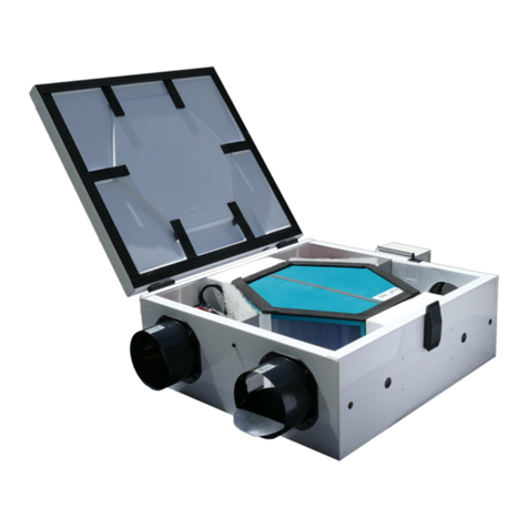
APPEARANCE AND FUNCTION OF EACH PART
17
1.
Surge input terminal [SURGE INPUT HOT / COM]
This surge input terminal is connected to LSS-6330. The supplied cable is used to connect it to
the surge output terminal of LSS-6330.
2.
Interlock terminal [INTERLOCK1]
This interlock connection terminal is connected to LSS-6330. The supplied cable is used to
connect it to the [INTERLOCK] terminal of LSS-6330.
3.
FG terminal [FG]
It is the FG terminal of the Unit. The supplied FG connection short bar is used to connect it to
LSS-6330.
4.
Resistor conversion box holder [RESISTOR BOX]
When the supplied resistor conversion box is not used, it is inserted into this space for storage.
5.
Matching resistor change terminal [160Ω]
When conducting the 10/700μwaveform test, the supplied resistor conversion box is connected
to set the resistor value to 25Ω.
6.
2-line/4-line switching terminal [2LINE / 4LINE]
The supplied short plug can be connected to set a 2-line or a 4-line configuration.
Do not use the short plug when conducting the 10/700μwaveform test in the 2-line configuration.
7.
Arrestor unit [A1/A2/A3/A4]
This arrestor unit is for surge decoupling.
When conducting a test, make sure to attach all of the four arrestors for your safety.
8.
Coupling arrestor unit [CA1/CA2/CA3/CA4]
This coupling arrestor unit is used for surge coupling. For the 2-line configuration of the Unit, use
at least CA1 and CA2. For the 4-line configuration, attach all arrestor units, CA1 to CA4. It is
recommended to use all of them.
Arrestor unit: Discharge voltage of 90V
Each arrestor is good for approximately 300 surges of 10/700us applied at 6kV. However,
since its life depends on the surge output current, the life is extended exponentially, as the
surge current decreases. It varies significantly, depending on the load conditions.
When the coupling arrestor unit and arrestor unit deteriorate, a surge cannot be applied to the
product under test correctly. The arrestor unit, in particular, is attached for surge decoupling
(for surge-back suppression). Be fully aware that when it deteriorates, the surge may go back
to the non-test side.
9.
Telecom line output terminals [TELECOM LINE OUTPUT 1/2/3/4/COM]
These are coupling output terminals for the telecom line. For the 2-line configuration, use output
terminals 1 and 2. For the 4-line configuration, use output terminals 1 to 4. The COM terminal is
connected when the EUT has an FG terminal.
These terminals output a high voltage surge. Mishandling or careless operation may result in
a fatality. Handle them carefully.


