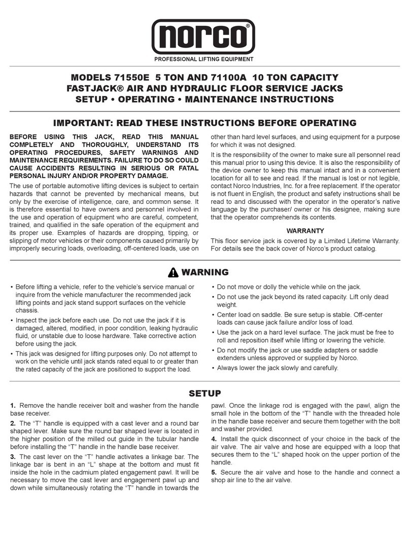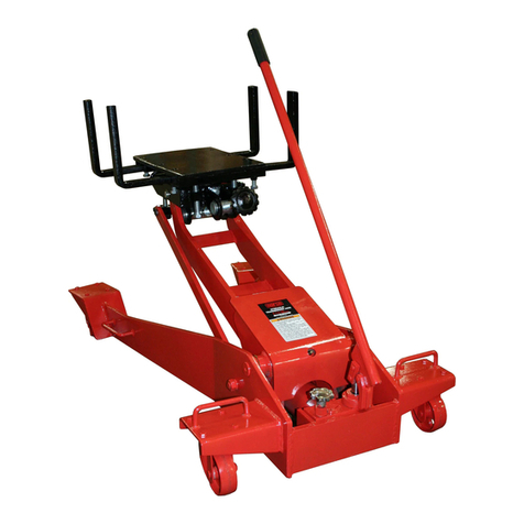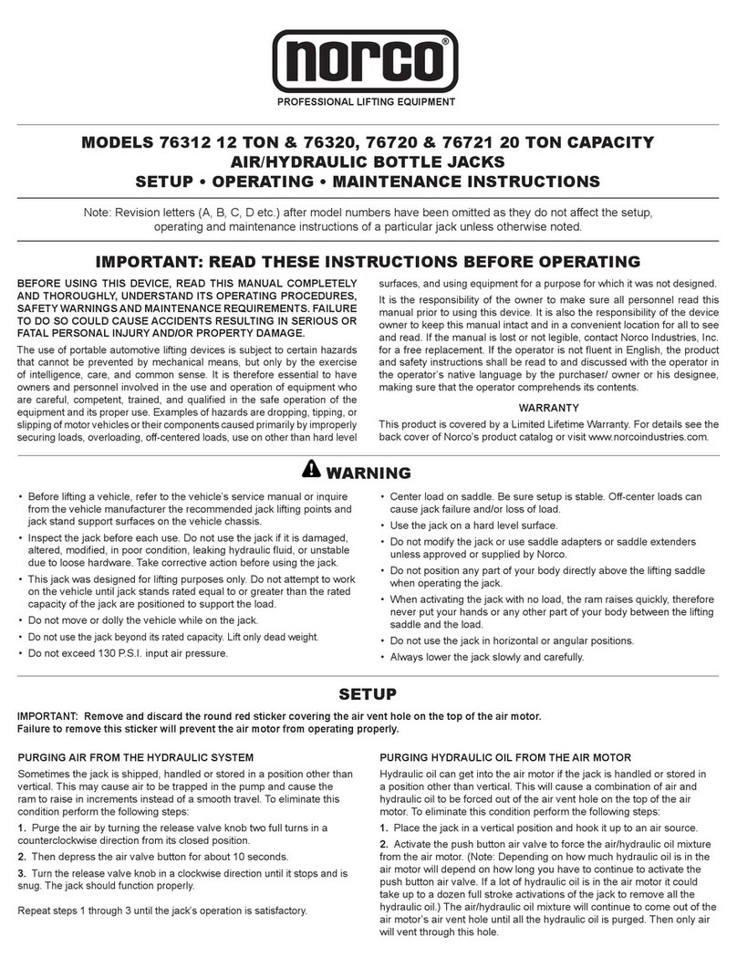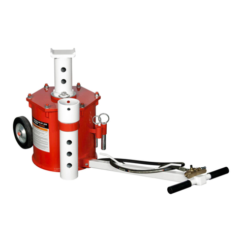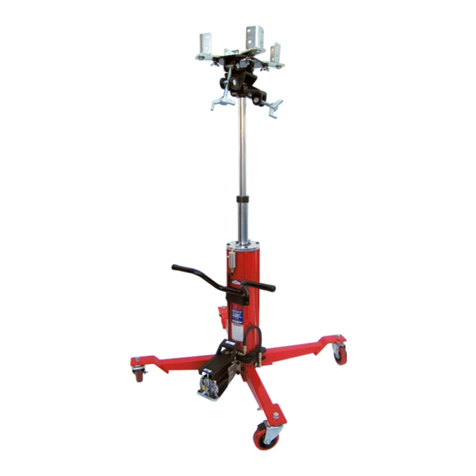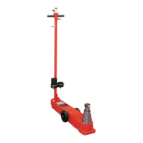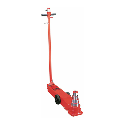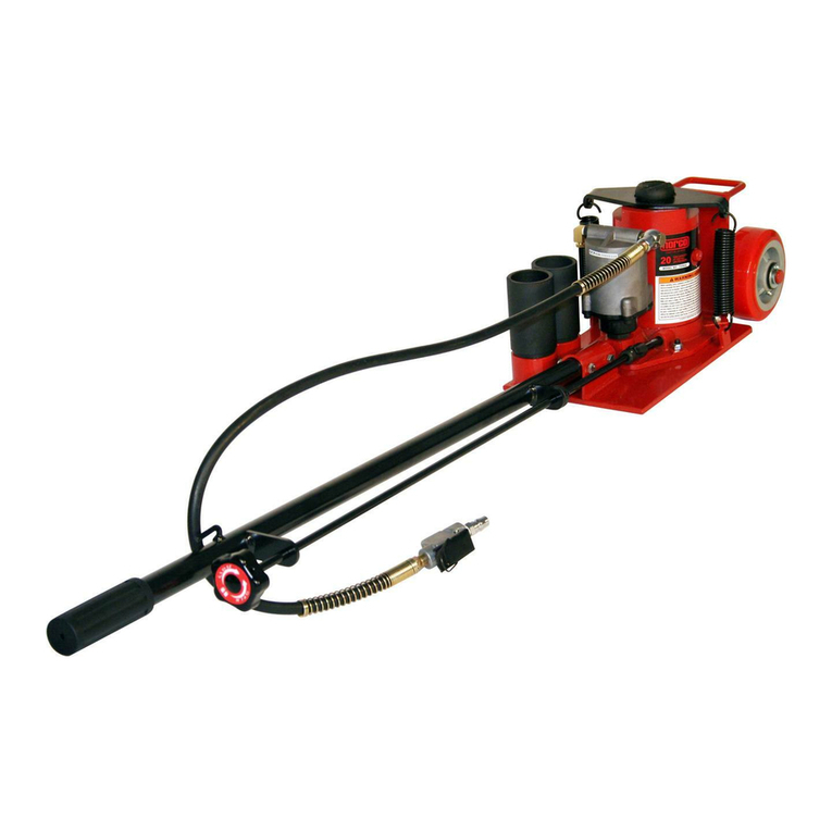
MODEL 71245A 2-1/4 TON CAPACITY AIR AND HYDRAULIC FLOOR JACK
SETUP • OPERATING • MAINTENANCE INSTRUCTIONS
PROFESSIONAL LIFTING EQUIPMENT
®
BEFORE USING THIS JACK, READ THIS MANUAL
COMPLETELY AND THOROUGHLY, UNDERSTAND ITS
OPERATING PROCEDURES, SAFETY WARNINGS AND
MAINTENANCEREQUIREMENTS.FAILURE TODOSOCOULD
CAUSE ACCIDENTS RESULTING IN SERIOUS OR FATAL
PERSONAL INJURY AND/OR PROPERTY DAMAGE.
The use of portable automotive lifting devices is subject to certain
hazards that cannot be prevented by mechanical means, but
only by the exercise of intelligence, care, and common sense. It
is therefore essential to have owners and personnel involved in
the use and operation of equipment who are careful, competent,
trained, and qualied in the safe operation of the equipment and
its proper use. Examples of hazards are dropping, tipping, or
slipping of motor vehicles or their components caused primarily by
improperly securing loads, overloading, off-centered loads, use on
other than hard level surfaces, and using equipment for a purpose
for which it was not designed.
It is the responsibility of the owner to make sure all personnel read
this manual prior to using this device. It is also the responsibility of
the device owner to keep this manual intact and in a convenient
location for all to see and read. If the manual is lost or not legible,
contactNorcoIndustries, Inc. for afreereplacement. If the operator
is not uent in English, the product and safety instructions shall be
read to and discussed with the operator in the operator’s native
language by the purchaser/ owner or his designee, making sure
that the operator comprehends its contents.
WARRANTY
This oor service jack is covered by a Limited Lifetime Warranty.
For details see the back cover of Norco’s product catalog.
IMPORTANT: READ THESE INSTRUCTIONS BEFORE OPERATING
WARNING
Before lifting a vehicle, refer to the vehicle’s service manual or• inquire from the vehicle manufacturer the recommended jack
lifting points and jack stand support surfaces on the vehicle
chassis.
Inspect the jack before each use. Do not use the jack if it is•
damaged, altered, modied, in poor condition, leaking hydraulic
uid, or unstable due to loose hardware. Take corrective action
before using the jack.
This jack was designed for lifting purposes only. Do not attempt to• work on the vehicle until jack stands rated equal to or greater than
the rated capacity of the jack are positioned to support the load.
Do not move or dolly the vehicle while on the jack.•
Do not use the jack beyond its rated capacity. Lift only dead • weight.
Center load on saddle. Be sure setup is stable. Off-center• loads can cause jack failure and/or loss of load.
Use the jack on a hard level surface. The jack must be free to• roll and reposition itself while lifting or lowering the vehicle.
Do not modify the jack or use saddle adapters or saddle• extenders unless approved or supplied by Norco.
Always lower the jack slowly and carefully.•
SETUP
Refer to the exploded view parts drawing for identication, 1.
location and position of parts.
Fit the handle halves together and secure them by tightening2.
the bolt and nut provided.
Using an open end or socket wrench, remove the hexagonal3.
head screw located on top of the handle receiver so the handle
can be inserted all the way.
Insert the handle in the handle receiver making sure the4.
conguration at the end of the handle ts into the slotted position
of the mechanism inside the handle receiver. The outside groove
at the bottom of the handle should align with the screw hole in the
handle receiver.
Install the quick disconnect of your choice in the back of the5.
air valve. The air valve and hose are equipped with a loop that
secures them to the “L” shaped hook on the upper portion of the
handle.
Secure the air valve and hose to the handle and connect a6.
shop air line to the air valve.
Install the hexagonal head screw in the screw hole in the7.
bottom of the handle receiver and tighten. This will secure the
handle in the handle receiver allowing you to maneuver the jack.
The hexagonal head screw will not bottom out on the handle thus
allowing you to rotate the handle in either direction for activation of
the release valve to either raise or lower the jack.
Install the quick disconnect of your choice in the back of the8.
air valve.
The air valve and hose are equipped with a loop that secures9.
them to the “J” hook on the upper handle.
Secure the air valve and hose to the handle and connect a10.
shop air line to the air valve.
Sometimes air gets trapped in the hydraulic system during11.
shipment.Anairboundhydraulicsystemfeelsspongywhenpumped
and sometimes the jack will not pump full incremental strokes.
PURGING AIR FROM THE HYDRAULIC SYSTEM
Open the release valve by turning the handle in aa. counterclockwise direction two full turns.
Pump the handle ten full strokes.b. Close the release valve by turning the handle in ac. clockwise direction until tight.
Pump the jack until the lift arm is extended tod. maximum height.
If the condition seems better, repeat steps “a” throughe.
“d” until all the air is purged from the system.

