OPERATING INSTRUCTIONS
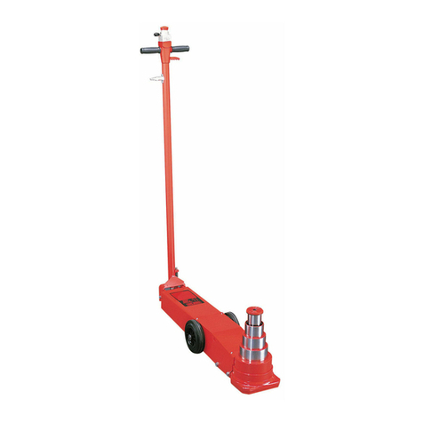
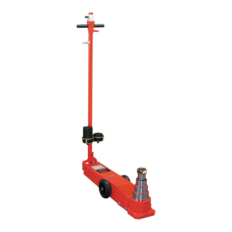
1. Become familiar with the identication and function of the
operating jack components.
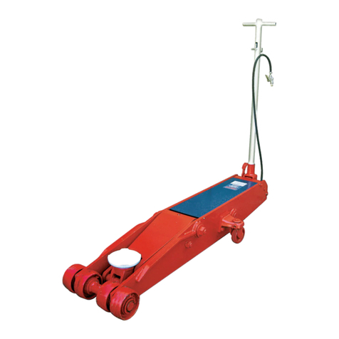
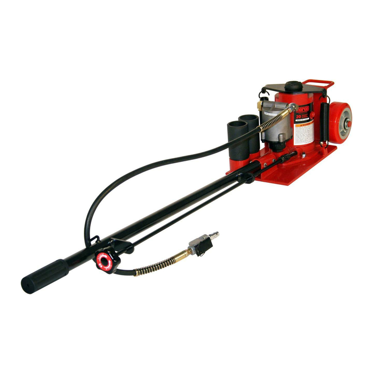
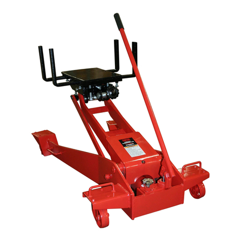
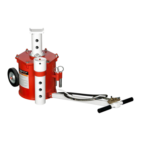
a. The ram is the shaft that comes out of the jack when you
depress the air valve and lifts the load.
b. The ram is equipped with an extension screw which can be
unscrewed to extend from the ram if there is not enough
hydraulic stroke to raise the load to the desired height.
Always use one of the three saddles listed below:
222328 2” diameter saddle
72203 2 ¼” extension saddle
72204 4” extension saddle
These can be inserted into the hole on top of the extension
screw. Choose the adapter/saddle that suits your lifting
situation.
2. Chock the vehicle’s tires that will not be lifted off the ground
prior to lifting the vehicle and if available, apply the emergency
brake or any other method of braking.
3. Position the jack at the designated lift point. Estimate the
required ram travel to raise the vehicle to the desired height. If the
desired vehicle height exceeds the entire ram travel, unscrew the
extension screw to make up the difference and add an extension
adapter if necessary.
4. Turn the knob at the top of the handle all the way in a clockwise
direction until tight. Lock the handle in a position that will not
interfere with the vehicle when raised or lowered. Keep the handle
in that locked position until the work is completed and you are
ready to remove the jack from use.
5. With the jack in the lowered position, push the jack under
the vehicle. IMPORTANT: Use the vehicle manufacturer’s
recommended lifting procedures and lifting points before lifting
loads.
6. In most cases 100 P.S.I. input air pressure (do not exceed 145
P.S.I.) will lift the maximum capacity load not to exceed 22 tons.
Depress the air valve until the top of the ram comes close to the
designated lift point. Make sure the designated lift point is at,
parallel to the ground and free from grease, any kind of lubricant,
or debris. Proceed with pumping the jack in order to lift the vehicle
to the desired height. During lifting, inspect the position of the jack
in relation to the ground and the ram in relationship to the load
to prevent any unstable conditions from developing. If conditions
look like they are becoming unstable, slowly lower the load and
make appropriate setup corrections after the load is fully lowered.
7. When the vehicle or load is lifted to its desired height, immediately
place safety support stands (jack stands) in their designated
locations and adjust the stands’ support columns up as close to
the designated vehicle support points as possible. Although jack
stands are individually rated, they are to be used in a matched
pair to support one end of a vehicle only. Stands are not to be
used to simultaneously support both ends or one side of a vehicle.
Slowly and carefully turn the release knob in a counterclockwise
direction to gently lower the vehicle onto the safety support stands
(jack stands). Make sure the vehicle is safely supported by the
safety support stands’ (jack stands’) saddles and not the locating
lugs of the saddles. Inspect the relationship of the safety support
stands (jack stands) with the ground and the safety support stand
(jack stand) columns and saddles with the vehicle to prevent any
unstable conditions. If conditions look unstable, close the jack’s
release knob and depress the air valve to raise the vehicle off the
safety support stands (jack stands). Make the appropriate setup
changes and slowly and carefully lower the vehicle onto the safety
support stand saddles.
8. After the work is done, close the release knob and depress the
air valve until the jack is high enough to remove the vehicle or load
from the safety support stand saddles. Be sure load is stable. If it is
not, lower load back onto safety support stands. Make appropriate
setup corrections and repeat the step again. Remove the safety
support stands from under the vehicle being very careful not to
move the vehicle.
9. Turn the release knob in a counterclockwise direction very
slowly and carefully to lower the vehicle or load down to the
ground.
REPAIR SERVICE
If your Norco product requires service or repair, contact the Norco
Customer Service Department for the location of the nearest Norco
Authorized Service Center.
Norco Industries, Inc.
365 West Victoria St.
Compton, CA 90220
(310) 639-4000 • Fax: (310) 639-7411
www.norcoindustries.com
It will be necessary to provide the Norco Authorized Service Center
with a copy of the bill of sale if requesting warranty repair. If the
authorized service center determines your product is eligible for
warranty repair, the repair will be made at no charge and returned
freight prepaid. The cost of non-warrantable service, repair, and
return freight is the customer’s responsibility.
1. Always store the jack in a well protected area where it will not
be exposed to inclement weather, corrosive vapors, abrasive dust,
or any other harmful elements. The jack must be cleaned of water,
snow, sand, or grit before using.
2. The jack must be lubricated periodically in order to prevent
premature wearing of parts. A general purpose grease must be
applied to the threads on the extension screw. Do not lubricate
any portion of the lift saddle and make sure the saddle is free from
grease, any kind of lubricant, or debris before using the jack.
3. It should not be necessary to rell or top off the reservoir with
hydraulic uid unless there is an external leak. An external leak
requires immediate repair which must be preformed in a dirt-
free environment by qualied hydraulic repair personnel who are
familiar with this equipment. Norco Authorized Service Centers are
recommended. IMPORTANT: In order to prevent seal damage
and jack failure, never use alcohol, hydraulic brake uid, or
transmission oil in the jack. Use Chevron Hydraulic Oil AW
ISO 32 or its equivalent Unocal Unax AW 150.
4. Every jack owner is responsible for keeping the jack label clean
and readable. Use a mild soap solution to wash external surfaces
of the jack but not any moving hydraulic components.
5. Do not attempt to make any hydraulic repairs unless you
are a qualied hydraulic repair person that is familiar with this
equipment.
PREVENTATIVE MAINTENANCE
72200

