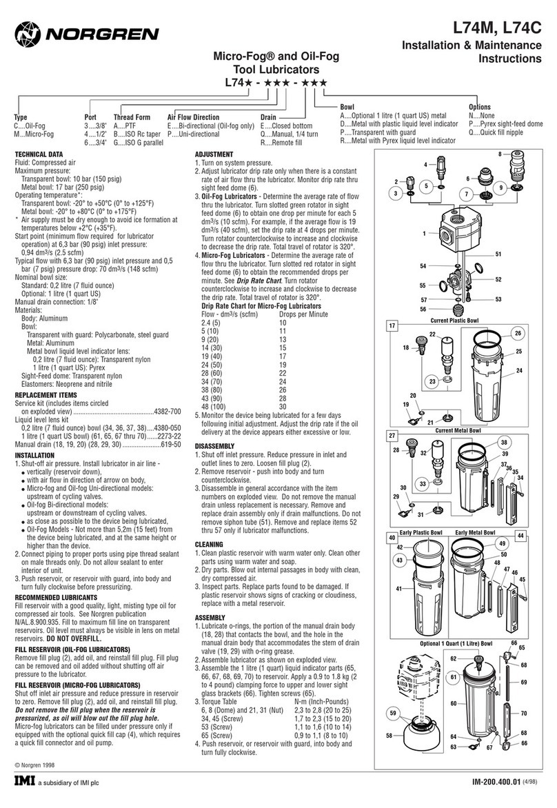
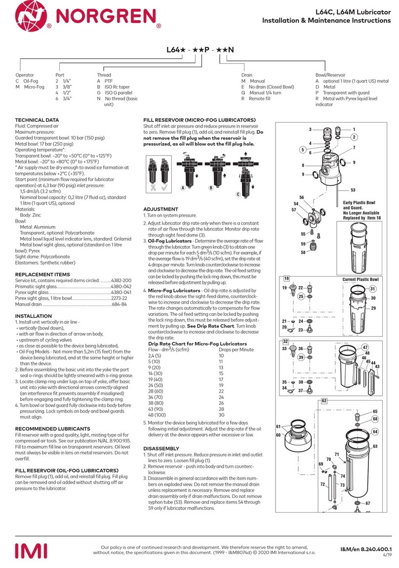
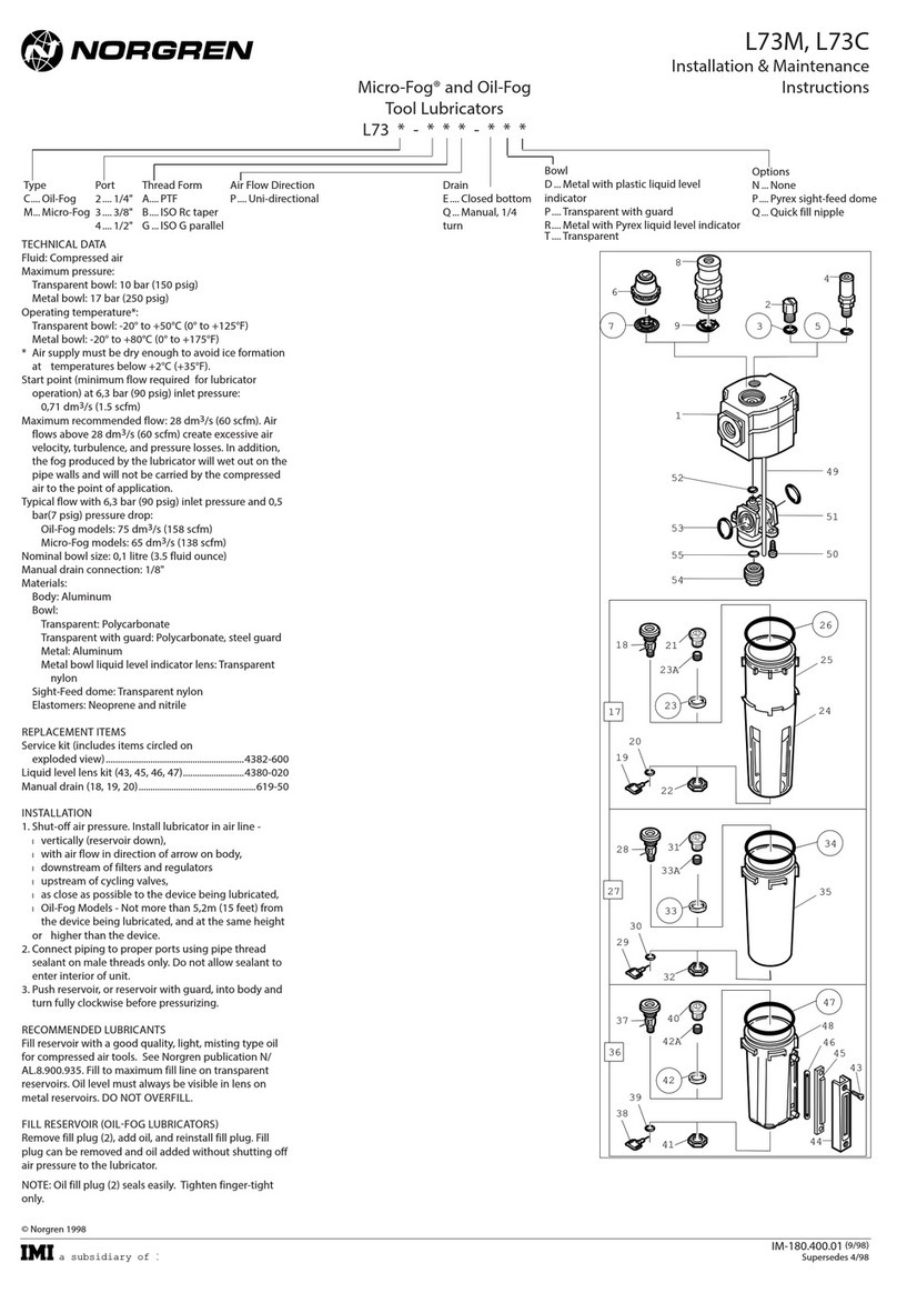
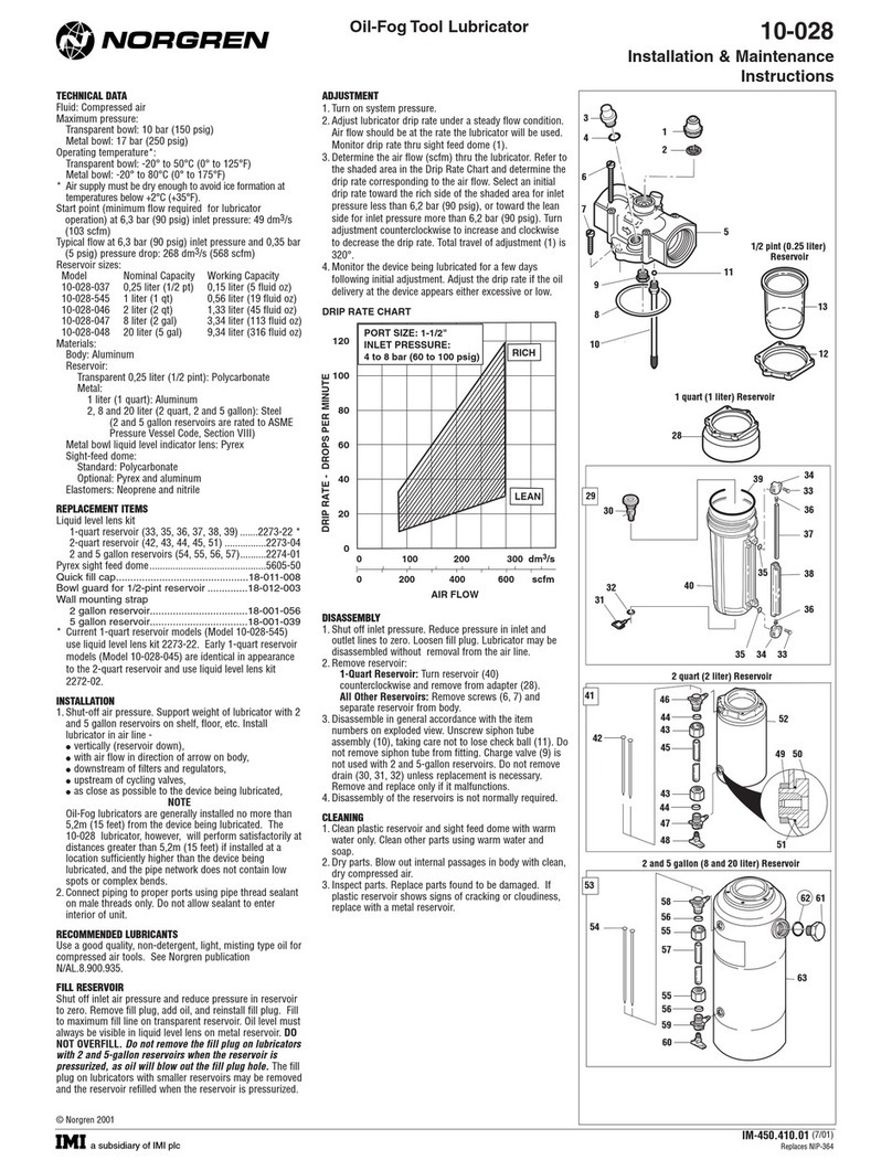
Norgren VR10 Installation and operating instructions

Operation & Service Manual
VR10 / VR15
With IO-Link Interface
Before starting work read these instructions.
This manual contains proprietary information. No part of this
publication may be reproduced, transcribed or transmitted
in any form without the written consent of the publisher.
Every eort has been made to ensure that the information
contained in this manual is accurate. All rights reserved.

2
Operation & Service Manual
VR10 / VR15 with IO-Link Interface
Construction & Design is subject to change (A1743-OPM-IL / Rev.002)
Change history:
The change history reflects all changes of the Operation & Service Manual, which were done after
the initial release.
Index
Chapters
Change description
Date
Name
001
All
New Release
27-Nov-2020
GG
002
All
Minor changes about pictures and texts
25-Jan-2021
GG
This Operation & Service Manual makes no claims of being complete as it does not cover all
variants of the VR10 / VR15 valve islands.
Therefore, this document is subject to extensions or changes.

3
Operation & Service Manual
VR10 / VR15 with IO-Link Interface
Construction & Design is subject to change (A1743-OPM-IL / Rev.002)
1 CONTENTS
1 CONTENTS .................................................................................................................. 3
2 ABOUT THIS DOCUMENTATION ............................................................................... 5
3 IMPORTANT HINTS ..................................................................................................... 6
3.1 GROUNDING AND EQUIPOTENTIAL BONDING ................................................. 6
3.2 USING AN IO-LINK MASTER ................................................................................ 6
4 ELECTRICAL CONNECTIONS .................................................................................... 7
4.1 IO-LINK CONNECTOR (PORT CLASS B) ............................................................. 8
4.2 ELECTRICAL DATA ............................................................................................... 8
5 SOLENOID NUMBER & VALVE STATION MAPPING ................................................ 9
5.1 MAPPING RULES FOR VALVE STATIONS £ 12 .................................................. 9
5.2 MAPPING RULES FOR 12 < VALVE STATIONS £ 24 .......................................... 9
6 COMMISSIONING ...................................................................................................... 10
6.1 HARDWARE CONFIGURATION ON IO-LINK MASTER ..................................... 10
6.2 IODD FILE INSTALLATION .................................................................................. 10
6.3 CONFIGURATION ON PORTS OF IO-LINK MASTER ........................................ 13
6.3.1 Submodules Configuration on Ports of IO-Link Master .................................. 13
6.3.2 Port Parameters Configuration ....................................................................... 14
6.4 DATA STORAGE FUNCTION .............................................................................. 15
6.5 PARAMETERIZATION ......................................................................................... 16
6.5.1 Online Adding Valve Island in Configurator ................................................... 16
6.5.2 Open Load Diagnostics Setting ...................................................................... 18
6.5.3 Fail Safe State Setting ................................................................................... 18
6.5.4 Voltage and Short Circuit Diagnostics ............................................................ 19
6.5.5 Cycle Counters Setting and Resetting ........................................................... 19
6.5.6 Valve Island Device Restart & Factory Reset ................................................ 21
7 FIRMWARE VERSION AND SERIAL NUMBER ........................................................ 22
8 DIAGNOSTICS ........................................................................................................... 23
8.1 DIAGNOSTICS INFORMATION PORTAL ........................................................... 23
8.1.1 Go Online Portal in TIA .................................................................................. 23
8.1.2 Configuration Software S7-PCT Portal .......................................................... 25

4
Operation & Service Manual
VR10 / VR15 with IO-Link Interface
Construction & Design is subject to change (A1743-OPM-IL / Rev.002)
8.2 OVERALL STATUS DIAGNOSTICS .................................................................... 26
8.3 SOLENOID STATUS DIAGNOSTICS .................................................................. 29
8.3.1 Short Circuit Diagnostics ................................................................................ 29
8.3.2 Open Load Diagnostics .................................................................................. 32
8.3.3 Cycle Overrun Diagnostics ............................................................................. 35
9 DIAGNOSTICS & OUTPUTS MAPPING OBJECT ..................................................... 38
10 LED INDICATION AND BAUD RATE SETTING ........................................................ 40
10.1 LED INDICATION .............................................................................................. 40
10.2 BAUD RATE SETTING ..................................................................................... 40
11 IO-LINK ERROR CODES ........................................................................................... 41
12 TECHNICAL DATA IO-LINK INTERFACE ................................................................. 42
13 CUSTOMER SUPPORT ............................................................................................. 43

5
Operation & Service Manual
VR10 / VR15 with IO-Link Interface
Construction & Design is subject to change (A1743-OPM-IL / Rev.002)
2 ABOUT THIS DOCUMENTATION
This user guide contains the information to set up and operate VR10 / VR15 valve island with IO-
Link Interface and to detect and resolve problems.
Note:
In addition to the specific information for the IO-Link variants, all data sheets and VR10 / VR15 PROTOCOL /
MULTIPOLE SERIES IP65 VERSION Operation & Service Manual are applicable and remain valid.
Refer also to the data sheets on the following web link:
§ https://www.norgren.com
Refer also to the valve island installation instruction in the following document:
§
“VR10 / VR15 PROTOCOL / MULTIPOLE SERIES IP65 VERSION Operation & Service Manual”
• This manual can be found on
https://www.norgren.com/uk/en/technical-support/installation-
maintenance-instructions/valves
Basic information about IO-Link can be found in the following documents:
§
“IO-Link System Description - Technology and Application.pdf”
•
https://io-link.com/IO-Link_System_Description.pdf
Further information about IO-Link is available on IO-Link websites:
§
https://io-link.com/
§
https://io-link.com/en/Technology
§
https://io-link.com/en/Download/

6
Operation & Service Manual
VR10 / VR15 with IO-Link Interface
Construction & Design is subject to change (A1743-OPM-IL / Rev.002)
3 IMPORTANT HINTS
3.1 GROUNDING AND EQUIPOTENTIAL BONDING
Proper grounding and equipotential bonding are very important to protect against electromagnetic
interferences in IO-Link networks. In order to reduce potential impact, should the valve island be
connected to the earth potential of the system or control cabinet via the earth connection on the
control module.
For proper grounding please use the terminal for earth screw (M4) on the upper side of the valve
island. For easy reference see item 4 in chapter 4. The cross-section of the used grounding cable
should be at least 0.75mm2.
3.2 USING AN IO-LINK MASTER
It is recommended to use an IO-Link master with port Class B to control VR10 / VR15 IO-Link
valve islands. The signal wire and valve power supply wire can be connected via this 5-wire
unshielded cable.

7
Operation & Service Manual
VR10 / VR15 with IO-Link Interface
Construction & Design is subject to change (A1743-OPM-IL / Rev.002)
4 ELECTRICAL CONNECTIONS
1- IO-Link connector (Port Class B)
(M12 x 1 | Male | 5 – pin | A – coded)
2- Status LEDs
3- Valve status LEDs
4- Earth screw (M4)
5- Baud rate setting switch (COM2 & COM3)

8
Operation & Service Manual
VR10 / VR15 with IO-Link Interface
Construction & Design is subject to change (A1743-OPM-IL / Rev.002)
4.1 IO-LINK CONNECTOR (PORT CLASS B)
§ Pin allocating of IO-Link connector
§ IO-Link connector wiring diagram
4.2 ELECTRICAL DATA
Specification
Remark
Valve voltage range (VA)
24VDC +10%/-5%
PELV
Electronics voltage range (VB)
24VDC +/-10%
PELV
Maximum currents
VA: n × 40 mA
VB: < 100 mA
n = number of solenoids
Voltages are galvanic decoupled
Yes
---
Protection against polarity reversal
Yes
---
Overcurrent protection VB, VA
Irreversible
---
Output polarity
PNP
---
M12 / 5 pins / Male Connector / A-coded / Class B
Pin No.
Function
1
L+ (VB +) 24V electronics power supply
2
2L+ (VA +) 24V valves power supply
3
L- (VB -) 0V electronics power supply
4
C/Q (COM) IO-Link communication
5
2M (VA -) 0V valves power supply
24V DC
24V DC
Valve Island
C/Q
Master

9
Operation & Service Manual
VR10 / VR15 with IO-Link Interface
Construction & Design is subject to change (A1743-OPM-IL / Rev.002)
5 SOLENOID NUMBER & VALVE STATION MAPPING
5.1 MAPPING RULES FOR VALVE STATIONS
£
12
§ If valve stations ≤ 12, 2 solenoid numbers are always reserved for each valve station. *
Detailed allocation is shown as below:
Station
#1
#2
#3
#4
#5
#6
#7
#8
#9
#10
#11
#12
Solenoid A
(14 Solenoid)
Sol.01
Sol.03
Sol.05
Sol.07
Sol.09
Sol.11
Sol.13
Sol.15
Sol.17
Sol.19
Sol.21
Sol.23
Output
0
Output
2
Output
4
Output
6
Output
8
Output
10
Output
12
Output
14
Output
16
Output
18
Output
20
Output
22
Solenoid B
(12 Solenoid)
Sol.02
Sol.04
Sol.06
Sol.08
Sol.10
Sol.12
Sol.14
Sol.16
Sol.18
Sol.20
Sol.22
Sol.24
Output
1
Output
3
Output
5
Output
7
Output
9
Output
11
Output
13
Output
15
Output
17
Output
19
Output
21
Output
23
Notes:
* For valve station with single solenoid, only Solenoid A (14 Solenoid) is connected.
Consider the one which is closest to control module as 1st station (Station #1)
5.2 MAPPING RULES FOR 12
<
VALVE STATIONS
£
24
§ If 12 < valve stations ≤ 24, special rules are required since only 1 solenoid number is
allocated to valve station with single solenoid:
• Sequence all solenoids following the rules below by starting from 1st station which is the
station closest to control module:
o If 1st station is with double solenoids, sequence solenoid A as Sol.01, solenoid B as
Sol.02, following 2nd station solenoid A as Sol.03, solenoid B as Sol.04……
o If 1st station is with single solenoid, sequence solenoid A as Sol.01, following 2nd
station solenoid A as Sol.02, solenoid B as Sol.03……
o If a station is originally configured as blank, always 2 solenoid numbers are allocated.
o The rest of stations should also adhere to the sequence rules above.
• A 16-station 24 solenoids valve island example is shown below:
Double
Solenoids
Double
Solenoids
Single
Solenoid
Single
Solenoid
Double
Solenoids
Double
Solenoids
Single
Solenoid
Double
Solenoids
Single
Solenoid
Double
Solenoids
Single
Solenoid
Double
Solenoids
Single
Solenoid
Single
Solenoid
Double
Solenoids
Single
Solenoid
Station
#1
#2
#3
#4
#5
#6
#7
#8
#9
#10
#11
#12
#13
#14
#15
#16
Solenoid A
(14 Solenoid)
Sol.01
Sol.03
Sol.05
Sol.06
Sol.07
Sol.09
Sol.11
Sol.12
Sol.14
Sol.15
Sol.17
Sol.18
Sol.20
Sol.21
Sol.22
Sol.24
Output
0
Output
2
Output
4
Output
5
Output
6
Output
8
Output
10
Output
11
Output
13
Output
14
Output
16
Output
17
Output
19
Output
20
Output
21
Output
23
Solenoid B
(12 Solenoid)
Sol.02
Sol.04
--*
--*
Sol.08
Sol.10
--*
Sol.13
--*
Sol.16
--*
Sol.19
--*
--*
Sol.23
--*
Output
1
Output
3
Output
7
Output
9
Output
12
Output
15
Output
18
Output
22
Note:
* For valve station with single solenoid, only Solenoid A (14 Solenoid) is allocated & connected.
Consider the one which is closest to control module as 1st station (Station #1).

10
Operation & Service Manual
VR10 / VR15 with IO-Link Interface
Construction & Design is subject to change (A1743-OPM-IL / Rev.002)
6 COMMISSIONING
Notes:
1. The method of IO-Link device installation strongly depends on the configuration software. Please refer to the
configuration software manual of your IO-Link master.
2. IO-Link master configuration software should support importing IODD files and support setting IO-Link
device parameters visually and graphically.
3. For those IO-Link masters which cannot import IODD files or cannot parameterize valve island visually or
graphically, alternative portable USB IO-Link master e.g. TMGTE IO-Link Device Tool can be used in conjunction
with respective software for IODD files and visual & graphical setting, or consult NORGREN directly.
4. All examples in this document are made with Siemens IO-Link master ET 200eco PN with PROFINET interface /
Port Class B and the configuration software SIMATIC S7-PCT Version 3.5 SP1.
5. All examples in this document are made with Siemens PLC S7-1212C and TIA Portal V15.1.
6.1 HARDWARE CONFIGURATION ON IO-LINK MASTER
As for the method of hardware configuration on Siemens IO-Link master ET 200eco PN in TIA
Portal V15.1 and SIMATIC S7-PCT V3.5 SP1, please refer to the following operation manual:
§
“Operating Instructions – SIMATIC
Distributed I/O ET 200eco PN.pdf”
https://support.industry.siemens.com/cs/attachments/29999018/et200eco_pn_operating_instructi
ons_en-US_en-US.pdf?download=true
6.2 IODD FILE INSTALLATION
A device description file (known as IODD) is needed for configuration of valve island. The IODD
files are XML based files, contains all information about the communication properties, the device
parameters, identification data, process data and diagnostics data, etc. of the valve island. It can
be used for all variants VR10 / VR15:
§ “Norgren-VR1X-IL-COM2-JJJJMMDD-IODDy.z.xml”
§ “Norgren-VR1X-IL-COM3-JJJJMMDD-IODDy.z.xml”
Notes:
1. “JJJJMMDD” (JJJJ-year, MM-month, DD-day) is date of release, “y.z” is version number.
2. COM2 & COM3 are baud rates, COM2=38.4 kbps, COM3=230.4 kbps. Default setting is COM3.
3. The configuration software of IO-Link master manufacturers should support read an IODD file and display all related
parameters of the valve island graphically.
4. Recommend installing the two IODD files and the IO-Link device will be found automatically whatever COM2 or
COM3 is set.

11
Operation & Service Manual
VR10 / VR15 with IO-Link Interface
Construction & Design is subject to change (A1743-OPM-IL / Rev.002)
The IODD file must be installed inside the IO-Link master configuration software SIMATIC S7-PCT:
§ Click “Options” -> “Import IODD…”.
§ Select source path where IODD file is stored, tick the IODD file and import.
The IODD files are provided by NORGREN and can be downloaded from the following web link:
§ https://www.norgren.com/uk/en/technical-support/software

12
Operation & Service Manual
VR10 / VR15 with IO-Link Interface
Construction & Design is subject to change (A1743-OPM-IL / Rev.002)
After the successful installation of the IODD file, the VR10 / VR15 is listed in the hardware
catalogue.

13
Operation & Service Manual
VR10 / VR15 with IO-Link Interface
Construction & Design is subject to change (A1743-OPM-IL / Rev.002)
6.3 CONFIGURATION ON PORTS OF IO-LINK MASTER
6.3.1 Submodules Configuration on Ports of IO-Link Master
Before commissioning the valve island, the behaviour must be assigned to ports of IO-Link master.
After the successfully adding the IO-Link master and configuring the network in TIA Portal, a
submodule with at least 10 bytes of IO-Link input data and at least 3 bytes of IO-Link output data
must be assigned to the associated port which the valve island is physically connected to.
The first possible submodule in the following example is: “IO-Link 16I/ 16 O + PQI” and it is carried
out as an example on port 3 of the IO-Link master.

14
Operation & Service Manual
VR10 / VR15 with IO-Link Interface
Construction & Design is subject to change (A1743-OPM-IL / Rev.002)
6.3.2 Port Parameters Configuration
After successfully adding the submodule to the associated port, the port parameters need to be
setting properly.
§ Diagnostics parameters setting:
• Ticking “No supply voltage 2L+”: Enabling of diagnostics in the case of missing or
insufficient load voltage 2L+.
• Ticking “Port Diagnosis”: Enabling of the diagnostics for the selected port.
• Ticking “Hardware interrupt (device notification)”: Enabling of hardware interrupts for the
selected port.
§ Port parameters setting:
• Keep “Port configuration without S7-PCT” un-ticked, which allow users to set parameters
and diagnostic features of VR10/ VR15 in S7-PCT. If “Port configuration without S7-PCT”
is ticked, user will not be able to set bespoke parameter and diagnostic features in S7-
PCT, but digital input/output is still communicated.
• Selecting option “IO-Link manual”: Activating parameter setting of the data storage
function for the selected port.
• Vendor ID: Manufacturer ID of connected IO-Link device, 1353 for VR10 / VR15.
• Device ID: Device ID of connected IO-Link device, 1 for COM3, 2 for COM2.
• If willing to execute data storage function, Vendor ID and Device ID must be set properly.
• Inspection / backup level: Enable / disable data storage function of the port.
• Selecting option “Type compatible (V1.1) with Backup & Restore” to enable data storage
function.

15
Operation & Service Manual
VR10 / VR15 with IO-Link Interface
Construction & Design is subject to change (A1743-OPM-IL / Rev.002)
6.4 DATA STORAGE FUNCTION
Valve island VR10 / VR15 with IO-Link Interface supports data storage function.
Make sure port parameters options are set as shown below to enable data storage function before
replacing valve island.
Follow the steps to replace valve island:
§ Disconnect valve island from IO-Link master.
§ Connect new valve island (with same configuration) to the same port on IO-Link master.
IO-Link master will copy parameter values from the data memory to the valve island automatically.
Note: Data storage function is with IO-Link version 1.1 or higher.

16
Operation & Service Manual
VR10 / VR15 with IO-Link Interface
Construction & Design is subject to change (A1743-OPM-IL / Rev.002)
6.5 PARAMETERIZATION
Note:
Parameterization can be carried out via the web interface (webserver integrated with IO-Link master) or via configuration
tools for IO-Link master. License could be required from IO-link master manufacture.
6.5.1 Online Adding Valve Island in Configurator
§ Make sure valve islands, IO-Link master and PLC are all connected properly and power on.
§ Right click ET 200eco PN master in TIA Portal to open S7-PCT.

17
Operation & Service Manual
VR10 / VR15 with IO-Link Interface
Construction & Design is subject to change (A1743-OPM-IL / Rev.002)
§ Click “Load to PG with Devices” button to find devices online.
§ After successfully adding devices, the valve islands will appear at related port.

18
Operation & Service Manual
VR10 / VR15 with IO-Link Interface
Construction & Design is subject to change (A1743-OPM-IL / Rev.002)
6.5.2 Open Load Diagnostics Setting
It is possible for VR10 / VR15 valve island to enable / disable the open load diagnostics for each
solenoid. If disabled, no open load diagnostic error appears. Otherwise a status diagnostic and
channel diagnostic with error description appears and SF LED on the IO-Link master change from
green to red colour.
Open load diagnostic is disabled by default.
§ Open “Parameters” tab and configure any solenoid in the parameter catalogue.
§ Select “disable diagnostics / enable diagnostics” options for open load diagnostics function.
§ Click “Load” button to write data to the valve island.
§ Solenoid number and valve station mapping relation is shown in Chapter 5.
6.5.3 Fail Safe State Setting
It is possible to define the behaviour of the outputs in case of broken IO-Link communication
between IO-Link master and valve islands. The following two states can be defined by the outputs:
1) Output — Off
2) Output — Hold last value
Caution: if the electronics power and valves power are broken, fail safe state function will not work.
§ Open “Parameters” tab and configure any solenoid in the parameter catalogue.
§ Select “Off / Hold last value” options for fail safe state function.
§ Click “Load” button to write data to the valve island.
§ Solenoid number and valve station mapping relation is shown in Chapter 5.

19
Operation & Service Manual
VR10 / VR15 with IO-Link Interface
Construction & Design is subject to change (A1743-OPM-IL / Rev.002)
6.5.4 Voltage and Short Circuit Diagnostics
VR10 / VR15 valve island supports voltage diagnostics for both electronic power and valve power
and short circuit diagnostics for each solenoid. These two diagnostic functions cannot be disabled.
§ In case of over / under voltage, a status diagnostic with error description appears, SF LED
on the IO-Link master change colour from green to red colour and the related VA / VB LEDs
on the valve island change colour from green to red (Overvoltage) / flashing red
(Undervoltage).
§ In case of short circuit, a status diagnostic and channel diagnostic with error description
appears and SF LED on the IO-Link master change from green to red colour.
6.5.5 Cycle Counters Setting and Resetting
VR10 / VR15 valve island supports cycle counting, count limit set and counter reset for each
solenoid.
§ Cycle counting
• Click “Online” button in S7-PCT to make devices online.
• Click the valve island and open “Diagnostics” tab to get detail cycle data.
• Solenoid number and valve station mapping relation is shown in Chapter 5.

20
Operation & Service Manual
VR10 / VR15 with IO-Link Interface
Construction & Design is subject to change (A1743-OPM-IL / Rev.002)
§ Count limit set
• Open “Parameters” tab and configure any solenoid in the parameter catalogue.
• Input the maximum cycles as required for count limit function.
• The max. limit is 232 in decimal and the default value is 232 as well.
• Click “Load” button to write data to the valve island.
• Solenoid number and valve station mapping relation is shown in Chapter 5.
§ Counter reset
• Open “Parameters” tab and click respective “Reset switching cycles Sol.xx” button for
specified valve.
• After clicking the reset button, the cycle data will be cleared and automatic write to the
valve island.
• Solenoid number and valve station mapping relation is shown in Chapter 5.
• If wants to reset all valve cycles by one button, just click “Application Reset” button.
• After clicking the button, the cycle data will be clear and automatic write to the valve
island.
Note: Counter reset is recommended after replacing with a new valve slice.
Other manuals for VR10
3
This manual suits for next models
1
Table of contents
Other Norgren Lubrication System manuals
