manuals.online logo
Brands
  1. Home
  2. •
  3. Brands
  4. •
  5. Nortek
  6. •
  7. Measuring Instrument
  8. •
  9. Nortek Scour Monitor User manual

Nortek Scour Monitor User manual

NORTEK QUICK GUIDE
Scour Monitor
Oct.
2017
Please check that all
expected items are
included in the shipment:
 The instrument
 External power/signal cable
 NORTEK equipment storage
box/toolkit
 USB to serial converter
 AC/DC voltage transformer
 Power cable
(European or American)
 Software on USB memory stick
 Final test check list
 Packing list
Install the Nortek software
The instrument’s software is
located on the attached
memory stick.
Please check the web
regularly for updates on both
software and firmware.
This Quick Guide provides you with the basic information you need to get the
Scour Monitor up and running as quickly as possible. If you are familiar with the
Nortek instruments, this guide may be all you need. If you are new to our
instruments and software we recommend that you check the web, were you will
find some useful information: www.nortekgroup.com
Preparation
1. Make a Reception Control. The items included are listed in the column to the
left and in the packing list.
2. Connect the battery.
3. Install the software located on the USB Memory stick. Once the installation is
complete you can launch the AquaPro Scour application.
4. Run a Functional Test:
a) Set the Measurement Interval to 1 second in the Deployment Planning
menu (see the next section). This allows you to retrieve data every
second.
b) Start the instrument and check that all the beams produce signals. When
the instrument pings in air, the signals will be nothing but noise.
c) Submerge the instrument in either a test tank or a bucket of water. Verify
the following readings:
 The signal strength observable in b) should rise noticeably
 Battery voltage (New battery: > 13V DC)
 The temperature
 Tilt the instrument to verify the pitch and roll readings.
Configuration
 Select Deployment Planning.
 The activated dialog contains all parameters required to specify the operation
of the instrument. Note that a description of each parameter can be found in
the application help, accessible from the dialog box. The Deployment Planning
frame on the right hand of the dialog displays performance parameters that are
automatically updated as you change the settings. Please pay special
attention to the battery utilization and the memory requirements.
 When finished, press OK to accept the changes. By using the Open/Save
commands in the File menu (or the corresponding toolbar buttons) the
deployment parameters can be saved to file at any given time and re-loaded
when it is time to actually deploy the instrument.
Getting Started
 Establish communication with the instrument.
 Select Start Recorder Deployment.
 Specify the date and time to start data recording.
 In the Name field enter up to 6 characters of text to identify the data file stored
in the reorder.
 In the File Comment box enter up to 180 characters of text which will be
included in the data file for the purpose of documenting the data set.
 After pressing OK the Set Clock dialog box is displayed. We recommend
setting the clock to PC time. The time reference is especially important in order
to ensure proper synchronization between the instrument and other data sets
collected independently.
 Press Yes to continue. A confirmation dialog will display the deployment
parameters and allow you to verify that the set-up is what you intended.
 Press Confirm to send the configuration to the instrument. The configuration
information from the deployment sequence is saved in a log file that has the
same name as the deployment.

Stop Recorder Deployment
 Select Stop Recorder Deployment. When data acquisition has stopped a
dialog will display the current Scour Monitor and PC clock time.
Data Retrieval
 Select Recorder Data Retrieval.
 The recorder overview dialog will show a list of all files currently stored in the
recorder, including the time of the first measurement and the size for each
file.
 Select a file in the list by clicking on the filename. Press Retrieve to specify
the name and where to save the file.
Data Conversion
 To convert binary data files retrieved from the recorder to a readable ASCII
format select Data Conversion from the Deployment menu or press the
Data Conversion toolbar button.
 Add files to the Files to convert list by using the Add file... file selection
dialog. To convert the files, select items in the list and press the blue arrow.
Specify the location for the converted files in the Save in folder field. An
optional pre- or postfix that will be added to the recorder filename may be
specified. Select from the View files drop-down list to open the converted
(ASCII) files in Notepad.
Tip! Check the retrieved data before deploying the instrument for the second
time. If something is wrong with the instrument, the deployment or the
configuration, this will be detected and the possibility of making the same
mistake twice is avoided.
On-line Data Collection
 An on-line data collection module is included for test purposes and to provide
data collection from the Scour Monitor in real time. The program will also
store data to binary files on the computer hard disk for post processing and
analysis.
 Select Start Data Collection from the On-line menu or press the toolbar
button to start data acquisition. The real time display shows velocity data and
sensor data as it is collected.
 To capture the data that comes in over the serial port to disk select Disk
Recording… from the On-line menu and define the name of a file (without
extension). Once this disk file is defined, the Start Disk Recording and Stop
Disk Recording menu items and toolbar buttons will be enabled. Once data
recording to disk has started, the status box on the display screen will show
the name of the disk file and its size.
 It is possible to get ASCII data out in real-time by using the Disk Recording
functionality.
 For users wanting to collect on-line data using a controller; check out the
System Integrators Guide for information about the data structure.
Basic Principles
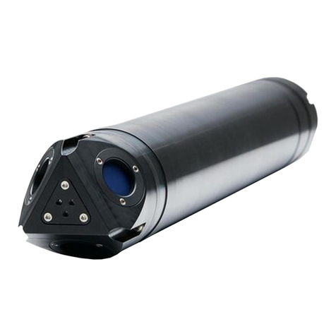
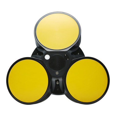
The Nortek Scour Monitor is
designed to provide a profile of
the seabed close to the base of
a mounting structure. It
operates as a four beam echo
sounder; it measures the
distance to the seabed along
four downward looking narrow
acoustic beams with angles 10,
20, 30 and 45 degrees from
the vertical. It comes in two
different versions; one that is
used for 0.1 to 10 meters
distance to the bottom (2 MHz)
and one that is used for 7 to 30
meters distance (1 MHz). The
intensity of the acoustic return
signal along the four beams is
measured. The bottom
reflection provides a strong
peak in signal amplitude, which
is used to determine the exact
distance
The basic mechanism causing
scour is the formation of
vortices, a result of pile-up of
water at the upstream side and
subsequent acceleration of the
flow around the obstruction, as
illustrated in the figure below.
Changes in the seabed level
are measured in real-time and
relayed back from the field,
even during storm periods,
thus providing invaluable
information for modelers of
these changes as they occur.
The data are corrected for tilt
and beam angles to provide
true bottom elevation as a
function of time.
Cables
The Scour Monitor comes standard with an 8-
conductor connector and cable, using RS422
communication. The table to the right lists the pin
assignments for the RS422 cable, and the figure
shows the inline 8-pin connector.
Communication baud rate: 9600 standard, 300-
115200 (user setting). Recorder download baud
rate: 600/1200 kBaud.
Ensure that the connectors and dummy plugs are
lubricated with dielectric silicone. We recommend
3M silicone spray. Note that the silicone grease
included in the shipment should be used on the O-
rings only.
Power and Communication
DC Input: 9-16 VDC
Battery DC-input: Nominal voltage: 13.5-18V
Absolute maximum DC input voltage: 18.6 V
System Integrator Manual
For more information about the options above and
how to control a Nortek product with a non-PC
controller, a System Integrator Manual is available
at the web.
Troubleshooting
As most problems are caused by simple mistakes,
please initially check if
 you have forgotten to power the system
 the connector has fallen out of the
computer
 you are using the wrong serial port
When all obvious mistakes are ruled out, please
turn to our Troubleshooting Guide available at
the web.
If the problem is still present contact Nortek
support at support@nortekgroup.com
Underwater Connector
Termination
Pin. No
Wire Color
Purpose
Pins
Description
3
b
lack
RS
422
Tx
+
Twisted
Pair
7
4
w
hite
RS422 T
x
-
2
7
b
lack
RS422 RX
-
Twisted
Pair
8
8
white/o
range
RS422 RX+
3
5
b
lack
Sync. Out
Twisted
Pair
6
white/p
urple
Sync. In
1
b
lack
Power Gnd
Twisted
Pair
2
w
hite
Power +
Screen terminated at pin 1 in underwater connector, unterminated at PC side.
Ref: N2100
-
108 rev
-
The wiring of the RS422 cable is shown in the table above. The Pin No. in
the table corresponds to the 8-pin connector in the figure below.

Other Nortek Measuring Instrument manuals

Nortek DVL 1000 300m User manual

Nortek

Nortek DVL 1000 300m User manual

Nortek Vectrino User manual

Nortek

Nortek Vectrino User manual

Nortek AWAC User manual

Nortek

Nortek AWAC User manual

Nortek Vector User manual

Nortek

Nortek Vector User manual

Nortek Signature VM User manual

Nortek

Nortek Signature VM User manual

Nortek Signature Series User manual

Nortek

Nortek Signature Series User manual

Nortek Vectrino User manual

Nortek

Nortek Vectrino User manual

Nortek Aquadopp Profiler User manual

Nortek

Nortek Aquadopp Profiler User manual

Nortek Signature55 User manual

Nortek

Nortek Signature55 User manual

Nortek Vector User manual

Nortek

Nortek Vector User manual

Nortek Aquadopp User manual

Nortek

Nortek Aquadopp User manual

Nortek Vectrino Profiler User manual

Nortek

Nortek Vectrino Profiler User manual

Popular Measuring Instrument manuals by other brands

Anritsu VectorStar ME7848E Series Maintenance manual

Anritsu

Anritsu VectorStar ME7848E Series Maintenance manual

Vega VEGAFLEX 80 Safety manual

Vega

Vega VEGAFLEX 80 Safety manual

USA Measurements US-M5 user manual

USA Measurements

USA Measurements US-M5 user manual

TSI Instruments 8525 Operation and service manual

TSI Instruments

TSI Instruments 8525 Operation and service manual

Triacta PowerHawk 6212 installation guide

Triacta

Triacta PowerHawk 6212 installation guide

horiba ISFET 0040-10D instruction manual

horiba

horiba ISFET 0040-10D instruction manual

TKA UV-Radiometer Operation manual

TKA

TKA UV-Radiometer Operation manual

Tektronix TLA6000 Series installation manual

Tektronix

Tektronix TLA6000 Series installation manual

Knick Protos CONDI 3400(X)-051 user manual

Knick

Knick Protos CONDI 3400(X)-051 user manual

FRC Air Sentinel AMA200 manual

FRC

FRC Air Sentinel AMA200 manual

Eastron SDM120C user manual

Eastron

Eastron SDM120C user manual

Endress+Hauser Analytikjena SELECT Head 8/250 ml operating manual

Endress+Hauser

Endress+Hauser Analytikjena SELECT Head 8/250 ml operating manual

McCrometer Dura Mag Installation, operation and maintenance manual

McCrometer

McCrometer Dura Mag Installation, operation and maintenance manual

Emerson Rosemount 5400 Series quick start guide

Emerson

Emerson Rosemount 5400 Series quick start guide

Amprobe SM-10 user manual

Amprobe

Amprobe SM-10 user manual

Minipa MLM-1011 instruction manual

Minipa

Minipa MLM-1011 instruction manual

OHAUS Defender 6000 instruction manual

OHAUS

OHAUS Defender 6000 instruction manual

Perfect Prime AQ9600 instruction manual

Perfect Prime

Perfect Prime AQ9600 instruction manual

manuals.online logo
manuals.online logoBrands
  • About & Mission
  • Contact us
  • Privacy Policy
  • Terms and Conditions

Copyright 2025 Manuals.Online. All Rights Reserved.