Nortek Vectrino User manual

USER GUIDE
OCTOBER 2004
Rev. C
ECTRINO
VELOCIMETER
V


NORTEK VECTRINO VELOCIMETER
User Guide
3
Rev. C • 10.2004
Copyright © Nortek AS 2004. October 2004. All rights reserved. This document may not – in whole or in
part – be copied, photocopied, translated, converted or reduced to any electronic medium or machine-readable
form without prior consent in writing from Nortek AS. Every effort has been made to ensure the accuracy of this
manual. However, Nortek AS makes no warranties with respect to this documentation and disclaims any implied
warranties of merchantability and fitness for a particular purpose. Nortek shall not be liable for any errors or for
incidental or consequential damages in connection with the furnishing, performance or use of this manual or the
examples herein. Nortek AS reserves the right to amend any of the information given in this manual in order to
take account of new developments.
Microsoft, ActiveX, Windows, Windows NT, Win32 are either registered trademarks or trademarks of Microsoft
Corporation in the United Sates and/or other countries. Other product names, logos, designs, titles, words or
phrases mentioned within this publication may be trademarks, servicemarks, or tradenames of Nortek AS or
other entities and may be registered in certain jurisdictions including internationally.
Nortek AS, Vangkroken 2, NO-1351 RUD, Norway.
Tel: +47 6717 4500 • Fax: +47 6713 6770 • e-mail: inquiry@nortek.no • www.nortek-as.com
ECTRINO
VELOCIMETER
V

4
Rev. C • 10.2004
Software updates and technical support
Find us on the world wide web:
www.nortek-as.com, www.nortek.no
Here you will find software updates and technical support.
Your Feedback is appreciated
If you find errors, misspelled words, omissions or sections poorly explained, please do not
hesitate to contact us and tell us about it at:
inquiry@nortek.no
We appreciate your comments and your fellow users will as well.
Nortek Forum Support
If you have comments, application tips, suggestions to improvements, etc. that you think
will be of general interest you should register on Nortek’s Forums at
www.nortek-as.com/cgi-bin/ib/ikonboard.cgi
and post your message there. The Forums also offer a great opportunity to share your
experience using Nortek sensors with other users around the world, and to learn from
their experience.
Communicating with us
If you need more information, support or other assistance from us, do not hesitate to
contact us:
Nortek AS
Vangk roken 2
NO-1351 RUD, Norway
Phone: +47 6717 4500, Fax: +47 6713 6770
e-mail: inquiry@nortek.no

NORTEK VECTRINO VELOCIMETER
User Guide
5
Rev. C • 10.2004
OVERVIEW
What’s in this Manual?
Chapter 1 – Getting Started
Here we introduce you to the Vectrino documentation, suggest which chapters it
is a must to read, and detail the warranty conditions.
Chapter 2 – Main Data
This chapter provides the technical specifications.
Chapter 3 – Technical Description
In this chapter you’ll find a description of the Vectrino’s functional principles,
some of the theory behind the Doppler principles, and practical aspects such as
the cable pin-outs.
Chapter 4 – Initial Preparation
An important part of the manual dealing with receiving control, installation of
the accompanying software and hints and tips making you sure that everything
works as intended before you start using your Vectrino.
Chapter 5 – Setting up for Operation
Here you’ll find a description of the controlling software as well as mounting
guidelines.

6
Rev. C • 10.2004
Chapter 6 – Use with other instruments
The Vectrino may be used with other Vectrinos, as a master (controlling the
sampling), or as a slave (having the sampling controlled from the outside). This
chapter describes what to consider when setting up a multisensor system.
Appendices
Appendix 1 – Troubleshooting Does your data look different from what you
expect? This chapter provides some answers to why they do..
Appendix 2 – Spare Parts Here you’ll find contains tips on how to keep your
Vectrino in good condition throughout its life..
Appendix 3 – Returning the Vectrino for Repair. In the unlikely event of the
need for a return for repair – the procedure to follow is given here.
OVERVIEW
What’s in this manual?

NORTEK VECTRINO VELOCIMETER
User Guide
7
Rev. C • 10.2004
DETAILS
The Table of Contents
CHAPTER 1 Getting Started................................................................................................................... 9
Warranty............................................................................................................................. 10
CHAPTER 2 Main Data .......................................................................................................................... 11
Specifications..................................................................................................................... 12
CHAPTER 3 Technical Description ..................................................................................................... 15
Vectrino Components ........................................................................................................ 15
Probe with Transducers ..................................................................................................... 15
Temperature Sensors.......................................................................................................... 16
Electronics Module............................................................................................................ 16
Power & Communication Cable ....................................................................................... 16
Functional Description ...................................................................................................... 16
Using the Doppler Effect ................................................................................................... 17
Vectrino Sonar Principles .................................................................................................. 17
Data Handling.................................................................................................................... 19
Interpreting and Analyzing the Data................................................................................. 19
ASCII formats .................................................................................................................... 20
Correcting for Sound Speed Errors................................................................................... 21
Error Codes and Status Codes........................................................................................... 21
CHAPTER 4 Initial Preparations .......................................................................................................... 23
Inspect the Received System ............................................................................................. 23
Installing the Vectrino PC Software ................................................................................. 24
Verifying Proper Operation ............................................................................................... 24
Run a Functionality Check ................................................................................................ 24
The Probe Check Feature................................................................................................... 26
CHAPTER 5 Setting Up for Operation................................................................................................. 29
Configuration..................................................................................................................... 29

8
Rev. C • 10.2004
The Configuration Settings................................................................................................ 31
Sampling Rate.................................................................................................................... 31
Nominal Velocity Range.................................................................................................... 31
Sampling Volume Height Setting ...................................................................................... 31
Transmit Length.................................................................................................................31
Power Level ....................................................................................................................... 32
Coordinate System............................................................................................................. 32
Speed of sound................................................................................................................... 32
Output Sync ....................................................................................................................... 32
Input Sync .......................................................................................................................... 32
Vertical/Horizontal Velocity Range................................................................................... 33
Analogue Outputs .............................................................................................................. 33
Mounting Guidelines ......................................................................................................... 33
Communication Between Vectrino and PC ...................................................................... 34
Using Long Cables............................................................................................................. 34
Changing the Baud Rate.................................................................................................... 35
CHAPTER 6 Use with Other Instruments ........................................................................................... 37
Synchronizing with Other Instruments............................................................................. 37
Specifications of Signal Levels.......................................................................................... 39
Appendix 1 Troubleshooting............................................................................................................... 43
Noisy Data ......................................................................................................................... 43
My Data Does Not Look Right.......................................................................................... 43
Grounding Problems..........................................................................................................44
Vibration in Mounting Fixture...........................................................................................44
Initial Problems? Did You Check This? ............................................................................ 44
No Detection of the Vectrino on the Serial Port................................................................ 45
Diagnostic Testing Using the Probe Check Function........................................................46
Appendix 2 Maintenance ..................................................................................................................... 49
Preventive Maintenance..................................................................................................... 49
Cleaning............................................................................................................................. 49
Corrective Maintenance .................................................................................................... 49
Appendix 3 Returning Vectrino for Repair ........................................................................................ 51
DETAILS
Contents
NORTEK VECTRINO VELOCIMETER
User Guide
9
Rev. C • 10.2004
CHAPTER 1
Getting Started
Thank you for purchasing a Nortek Vectrino Velocimeter! The Vectrino has
been designed to provide you with many years of safe, reliable service.
Your approach to the Vectrino documentation depends on what you want to do
and how much you already know. Depending on your requirements you may find
that you use some parts of this manual regularly and others not at all.
However, before you start to use the system we do recommend that you look
through this user manual.
To get you up and running:
•Before you start using the Vectrino, please familiarize yourself with the in-
strument by reading the chapters 2 and 3 of this user guide.
•Verify that you have received all parts and run a functional test of the Vec-
trino according to the procedures given in chapter 4.
•Start using the Vectrino according to procedures in chapter 5.

10
Rev. C • 10.2004
Warranty
In order to stay up-to-date and receive news and tips from the factory you should
register at our web site. Use the Internet and go to http://www.nortek-as.com/
newsletter.php. Enter your name, e-mail address and topics of interest.
We also recommend our User Forum where you may post questions and discuss
with other people in the oceanographic community. To get to the User Forum
enter http://www.nortek-as.com and click on Forum. If you have no internet ac-
cess or, if you – for any other reason – prefer traditional mail or telefax, you may
fill in and return the registration part of the warranty sheet accompanying your
Nortek product.
Nortek AS grants a one year limited warranty that extends to all parts and labour
and covers any malfunction that is due to poor workmanship or due to errors in
the manufacturing process. The warranty does not cover shortcomings that are
due to design, nor does it cover any form of consequential damages as a result of
errors in the measurements.
In the unlikely event of trouble with your Nortek product, first try to identify the
problem by consulting the documentation accompanying your Nortek product. If
you need further assistance when trying to identify the problem, please contact
your local Nortek representative or the factory.
Please make sure you receive a Return Merchandise Authorization (RMA)
before any product or module is returned. An RMA can be obtained using our
e-mail address: inquiry@nortek.no or our Fax No.: +47 6713 6770. See also Ap-
pendix 3.
CHAPTER 1
Getting Started

NORTEK VECTRINO VELOCIMETER
User Guide
11
Rev. C • 10.2004
CHAPTER 2
Main Data
The Vectrino Velocimeter measures water speed using the Doppler effect.
You hear the Doppler effect whenever a train passes by – the change in pitch you
hear tells you how fast the train is moving. The Vectrino uses the Doppler effect
to measure current velocity by transmitting a short pulse of sound, listening to
its echo and measuring the change in pitch or frequency of the echo.
The Vectrino velocimeter
operating principle. A pulse
is transmitted from the
centre transducer, and the
doppler shift introduced by
the reflections from particles
suspended in the water, is
picked up by the 4 receivers.
Sampling volume

12
Rev. C • 10.2004
Specifications
WATER VELOCITY MEASUREMENT
Range: ±0.01, 0.1, 0.3, 1, 2, 4m/s (software selectable)
Accuracy: ±0.5% of measured value ±1mm/s
Sampling rate (output) 1–25Hz, 1–200Hz (Vectrino
+
firmware only)
Internal sampling rate: 200–5000Hz
SAMPLING VOLUME
Distance from probe: 0.05m
Diameter: 6mm
Height (user selectable): 3–15mm
DOPPLER UNCERTAINTY (noise)
Typ. uncer tainty at 25 Hz: 1% of velocity range
ECHO INTENSITY
Acoustic frequency: 10 MHz
Resolution: 0.45 dB
Dynamic range: 60 dB
SENSORS
Temperature (thermistor embedded in probe)
Range: –4ºC to 40ºC.
Accuracy/Resolution: 1ºC / 0.1ºC.
Time response: 5 min
DATA COMMUNICATION
I/O: RS-232
Baud rate: 300–115 200
User control: Handled via Vectrino WIN32® software, ActiveX function calls,
or direct commands
Analogue outputs: 3 channels standard, one for each velocity component.
Output range is 0–5V, scaling is user selectable
Synchronization: SynchIn and SynchOut
SOFTWARE (VECTRINO)
Operating system: Windows®98, Windows NT®4.0, Windows®2000,
Windows®XP
Functions: Instrument configuration, data collection, data storage. Probe test
modes.
POWER
DC Input: 12–48VDC
Peak current: 2.5A at 12VDC (user selectable)
Max consumption @ 200Hz: 1.5W
CHAPTER 2
Main Data

NORTEK VECTRINO VELOCIMETER
User Guide
13
Rev. C • 10.2004
CONNECTORS
Bulkhead: IP68 connector or MCBH-12-FS, bronze (Impulse), (see also Op-
tions below)
Cable: IP68 or PMCIL-12-MP (see also Options below)
MATERIALS
Standard model: Delrin housing. Stainless steel (316) – probe and screws
ENVIRONMENTAL
Operating temperature: –5ºC to 45ºC
Storage temperature: –15ºC to 60ºC
Shock and vibration: IEC 721-3-2
DIMENSIONS
Cylinder: 70 mm
Length: 388mm.
OPTIONS
•Standard or Vectrino
+
firmware (upgrade to Vectrino
+
firmware is also
available as retrofit)
•4-beam down-looking probe on 40-cm stem
or 4-beam probe on 1-m cable
•Upgrade kit from NDV or ADV™
•12-pin IP68 waterproof (1h@20m)
or Impulse 12-pin underwater connector
•10, 20, 30 or 50 m cable with choice of connectors (IP68 or Impulse under-
water connector)
•RS-232-to-USB converter (one-to-one, four-to-one or eight-to-one)
•Combined transportation and storage case

14
Rev. C • 10.2004
CHAPTER 2
Main Data

NORTEK VECTRINO VELOCIMETER
User Guide
15
Rev. C • 10.2004
CHAPTER 3
Technical Description
Vectrino Components
POM (Delrin) instrument housing and endcaps
Integrated shape zinc anode
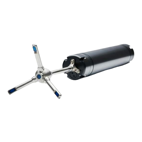
Miniature 4-beam stainless steel probe with temperature sensor
5cm distance to sampling volume
Underwater mateable connector shown
Low cost lab-type connector available
Recesses for clamping
Rigid stem shown, cable probe available
Title: Vectrino Isometric Views
Date: 08/07/04 Dimensions are in milimeters
Copyright Nortek AS
Probe with Transducers
The probe is mounted either on a fixed stem connected to the main housing
through the probe end bell or a cable connected to the main housing through the
same probe end bell.

16
Rev. C • 10.2004
End bell with connector
External
view
AB
CDEF
GH J K
LM
1
23
4
5
6
7
8
9
10
11
12
Pin No. Function
1AAnalogueout1
2BAnalogueout2
3CAnalogueout3
4DAnalogueout4
5EGnd
6FSynchIn
7GSynchOut
8HGnd
9JTx
10 K Rx
11 L Gnd (Power –)
12 M Power + (12–48V)
IP68 connector
(external view)
Impulse connector
(external view)
The two connectors available
for the Vectrino and the
corresponding pin-outs.
The probe consists of four receive transducers, each mounted inside a receiver
arm, and a transmit transducer in the centre. The transducers are each covered
with a hard epoxy and the probe is otherwise titanium.
Temperature Sensors
The temperature sensor is located inside the probe head.
Electronics Module
The electronics module is located inside the pressure case, and is a single board
that holds the power transmitter, analogue and digital signal processing, power
conditioning and the standard data recorder.
Power & Communication Cable
The power and communication cable is connected to the end bell connector. The
cable supplies external DC power (12–48V), connects an external computer to
the Vectrino for 2-way serial communication, for analogue output of the three
velocity components, and furthermore it provides synchronization options (Vec-
trino can be used both as master and as slave to synchronize measurements with
other Vectrinos and/or other transducers).
Cable Wiring. The Vectrino comes standard with a 12-conductor connector and
cable. The connector type is either IP68 connector or MCBH-12-FS, bronze
(Impulse). The Vectrino power lines are diode protected, so you don’t have to
worry about wiring the Vectrino power backwards – this will not damage your
instrument. The pin-out is shown in the side bar.
Functional Description
This section briefly describes some of the underlying principles that control the
operation and application of the Vectrino Velocimeter.
The Vectrino has two modes of operation:
• Command mode.
A Vectrino in command mode is ready to accept your in-
structions.
• Data Acquisition Mode. The Vectrino enters data acquisition mode when you
click any of the Start commands (e.g. Start Data Collection) in the Vectrino
software. The Vectrino collects data without breaks.
CHAPTER 3
Technical Description

NORTEK VECTRINO VELOCIMETER
User Guide
17
Rev. C • 10.2004
Using the Doppler Effect
You hear the Doppler effect whenever a train passes by – the change in pitch you
hear tells you how fast the train is moving. The Vectrino uses the Doppler effect
to measure current velocity by transmitting short pairs of sound pulses, listening
to their echoes and, ultimately, measuring the change in pitch or frequency of
the returned sound.
Sound does not reflect from the water itself, but rather from particles suspended
in the water. These particles are typically zooplankton or suspended sediment.
Long experience tells us that these small particles move with the same average
speed as the water – the velocity it measures is consequently the velocity of the
water.
Vectrino Sonar Principles
In contrast to standard Doppler profilers and current meters, the Vectrino is a
bistatic sonar. This means that it uses separate transmit and receive beams. It
transmits through a central beam and receives through four beams displaced off
to the side.
The figure below shows how the beams intersect each other 50 mm from the
transmitter. The measurement volume is defined by this intersection and by
range gating in time. The transmit transducer sends a short pulse that covers
3–15 mm vertically (user adjustable), and the receivers listen to an echo that cor-
responds from this volume. The diameter of the volume is 6 mm. The Vectrino
uses four receivers, all focused on the same volume, to obtain the three velocity
components from that very volume.
The beams intersect at
approximately 50 mm from the
transmitter. The exact position
varies from one Vectrino to
another, but all Vectrinos are
individually measured and
calibrated before leaving the
factory. This exact position is
then stored in each Vectrino’s
head configuration file.
The Vectrino uses four
receivers – all focused on the
same volume – to obtain the
three velocity components. See
also the text for more on this.
Approximately 50mm
3–15 mm (user adjustable)
The figure below shows that a transmit/receive beam pair is sensitive to velocity
in the direction of the angular bisector between the beams. The arrow indicates
a positive velocity.

18
Rev. C • 10.2004
The transmit/receive beam pair
is sensitive to velocity in the
direction of the angular bisector
between the beams. The arrow
indicates a positive velocity.
Since the receive beams are
slanted at 30°, all three beam
pairs measure velocity that is
only 15° away from the transmit
beam.
30°
v
Since the receive beams are slanted at 30°, all three receivers measure the veloc-
ity that is slanted about 15° from the transmit beam.
This means that the Vectrino is more sensitive to the Z-velocity (the component
parallel to the transmit beam) than it is to the X- or Y-velocity. Consequently, the
Z-velocity component yields a lower measurement uncertainty.
Coordinate System. The Vectrino measures velocity components parallel to its
three beams, or in beam components. It reports data in Beam or XYZ coordinate
systems.
Defining the XYZ coordinates.
The arm with the marking
defines the X-direction. The
Z-direction is towards the
elctronics of the Vectrino.
View direction
X
Y
X-indicator
Z
X
Z
X
The XYZ coordinates are relative to the probe and independent of whether the
Vectrino points up or down.
In XYZ coordinates, a positive velocity in the X-direction goes in the direction
of the X-axis arrow.
Velocity Uncertainty. The Vectrino velocity is an average of many velocity es-
timates (called pings). The uncertainty of each ping is dominated by the short-
term error. We reduce the measurement uncertainty by averaging together many
pings. There is a limit to how much you can reduce your uncertainty. We call this
limit the long-term bias.
The long-term bias depends on internal signal processing, especially filters, and
CHAPTER 3
Technical Description

NORTEK VECTRINO VELOCIMETER
User Guide
19
Rev. C • 10.2004
on your beam geometry. The long-term bias in the Vectrino is typically a frac-
tion of 1 cm/s. The Vectrino software predicts errors based on the short-term
error of a single ping and the number of pings averaged together.The short-term
error of a single ping depends on the size of the transmit pulse and the measure-
ment volume, and it depends on the beam geometry. Averaging multiple pings
reduces errors according to the formula:
Vmean= Vping
N
in which is the standard deviation and Nis the number pings you average
together.
Note: The Vectrino software predicts the instrumental error only. In many
situations, the environmental turbulence or surface waves will dominate the
short term velocity fluctuations.
Data Handling
The Vectrino software creates binary files, which can be converted to ASCII
format files, using the Vectrino software.
• The *.hd r file is a self-documented table. Please note that this file contains the
detailed data format of all the other ASCII files.
• The *.dat files contains velocity and pressure data at the full sample rate.
• The *.sen files contains system data such as the time/date, compass, tilt, tem-
perature, battery voltage, etc. These data are sampled once per second.
You will find the ASCII files easy to import into most spreadsheets and data
analysis programs. NORTEK recommends the use of a specially developed pro-
gram for turbulent data analysis. The program is called ExploreV. See Appendix
2–Optional configurations and features for more on this.
Interpreting and Analyzing the Data
We strongly recommend the use of our internet pages to gain access to the latest
technical notes and user-experience regarding data analysis and related matters.
If the data looks different from what you expected and you have reason to be-
lieve that this is instrument or deployment related, consult Chapter 10 – Trou-
bleshooting before taking other actions.

20
Rev. C • 10.2004
ASCII formats
The ASCII data format is subject to change, but the current format is always de-
scribed in the header (.hdr) file generated by the data conversion function.
Velocity Data Header
Col Type Unit
1Distance m
2Quality counts
3Lag1used counts
4Lag2used counts
5 Noise amplitude (Beam1) counts
6 Noise amplitude (Beam2) counts
7 Noise amplitude (Beam3) counts
8 Noise amplitude (Beam4) counts
9Noisecorrelation(Beam1) %
10 Noise correlation (Beam2) %
11 Noise correlation (Beam3) %
12 Noise correlation (Beam4) %
13 Temperature °C
14 Soundspeed m/s
Velocity Data
Col Type Unit
1Status
2 Ensemble counter
3Velocity(Beam1|X) (m/s)
4Velocity(Beam2|Y) (m/s)
5Velocity(Beam3|Z) (m/s)
6Velocity(Beam4|Z2) (m/s)
7Amplitude(Beam1) (counts)
8Amplitude(Beam2) (counts)
9Amplitude(Beam3) (counts)
10 Amplitude (Beam4) (counts)
11 SNR (Beam1) (dB)
12 SNR (Beam2) (dB)
13 SNR (Beam3) (dB)
14 SNR (Beam4) (dB)
15 Correlation (Beam1 (%)
16 Correlation (Beam2) (%)
17 Correlation (Beam3) (%)
18 Correlation (Beam4) (%)
CHAPTER 3
Technical Description
Other manuals for Vectrino
1
Table of contents
Other Nortek Measuring Instrument manuals

Nortek
Nortek Signature Series User manual

Nortek
Nortek AWAC User manual

Nortek
Nortek DVL 1000 300m User manual

Nortek
Nortek Aquadopp Profiler User manual

Nortek
Nortek Signature VM User manual

Nortek
Nortek Vector User manual

Nortek
Nortek Vectrino Profiler User manual

Nortek
Nortek Vectrino User manual

Nortek
Nortek Aquadopp User manual

Nortek
Nortek Signature55 User manual