Nortek Vectrino User manual

USER GUIDE
2009
ECTRINO
VELOCIMETER
V


Vectrino 3
ECTRINO
VELOCIMETER
Copyright © Nortek AS 2009. All rights reserved. This document may not – in whole or in part – be
copied, photocopied, translated, converted or reduced to any electronic medium or machine-readable
form without prior consent in writing from Nortek AS. Every effort has been made to ensure the
accuracy of this manual. However, Nortek AS makes no warranties with respect to this documentation
and disclaims any implied warranties of merchantability and fitness for a particular purpose. Nortek
shall not be liable for any errors or for incidental or consequential damages in connection with the
furnishing, performance or use of this manual or the examples herein. Nortek AS reserves the right to
amend any of the information given in this manual in order to take account of new developments.
Microsoft, ActiveX, Windows, Windows 2000, and Win32 are either registered trademarks or
trademarks of Microsoft Corporation in the United States and/or other countries. Other product names,
logos, designs, titles, words or phrases mentioned within this publication may be trademarks,
servicemarks, or tradenames of Nortek AS or other entities and may be registered in certain jurisdictions
including internationally.
Nortek AS, Vangkroken 2, NO-1351 RUD, Norway.
Tel: +47 6717 4500 • Fax: +47 6713 6770 • e-mail: [email protected] • www.nortek-as.com
V


Vectrino 5
TABLE OF CONTENTS
Introduction ....................................................................................................7
Getting Started...........................................................................................................7
Contents of Your Shipment .......................................................................................8
Product Specification ....................................................................................................9
Mechanical.................................................................................................................9
Sampling Volume ......................................................................................................9
Echo Intensity ............................................................................................................9
Sensors....................................................................................................................10
Data Communication ...............................................................................................10
Multi Unit Operation.................................................................................................10
Software (“Vectrino”) ...............................................................................................10
Power.......................................................................................................................11
Connectors ..............................................................................................................11
Materials ..................................................................................................................11
Environmental..........................................................................................................11
Options ....................................................................................................................11
Technical Description ..................................................................................................13
System Components ...............................................................................................13
Functional Description ..................................................................................................15
Doppler Theory........................................................................................................ 15
Data Handling..........................................................................................................16
Software ..................................................................................................17
Vectrino software options ........................................................................................17
Installation................................................................................................................18
Configurations..........................................................................................................18
Mounting Guidelines ..................................................................................................19

6
Content
What to consider......................................................................................................19
Test and Verification ..................................................................................................21
Communication........................................................................................................21
Transducers.............................................................................................................22
Probe Check ............................................................................................................ 22
Synchronizing Multiple Instruments ..................................................................................................25
Synchronizing Multiple Vectrinos.............................................................................25
Synchronizing From a TTL Source..........................................................................26
How Synchronization Works....................................................................................26
Maintenance ..................................................................................................27
Preventive Maintenance ..........................................................................................27
Corrective Maintenance........................................................................................... 27
Upgrading ..................................................................................................29
Upgrading Software.................................................................................................29
Upgrading Firmware ................................................................................................29
Further Information and Help ..................................................................................................31
Visit www.nortek-as.com .........................................................................................31
Nortek’s Forum ........................................................................................................31
Contact Information ................................................................................................. 32
Returning Your Vectrino for Repair ..................................................................................................33
Returning your Vectrino...........................................................................................33
Insurance ................................................................................................................. 33
Customs regulations ................................................................................................34
Drawings and Dimensions ..................................................................................................37

Vectrino 7
Chapter 1
Introduction
Thank you for purchasing Nortek’s Vectrino velocimeter! Your Vectrino has
been designed to provide you with many years of safe, reliable service.
The Vectrino is a high-resolution acoustic velocimeter used to measure
turbulence and 3D water velocity in a wide variety of applications from the
laboratory to the ocean. The basic measurement technology is coherent
Doppler processing, which is characterized by accurate data and no
appreciable zero offset.
Getting Started
This guide in combination with the Quick Start guide which is part of the
Help function in your Vectrino software, will help you getting started with
your Vectrino. As initial preparation for using your new Vectrino
velocimeter, we recommend the following steps:
1Verify that you have received all parts (see next page).
2Install the Vectrino software on a computer (see chapter 5, Software).
3Perform a functional test of your new Vectrino (see chapter 7, Test and
Verification).
4Mount the Vectrino in accordance with the guidelines (see chapter 6,
Mounting Guidelines).

8Chapter 1
Introduction
.
Contents of Your Shipment
When you receive your Vectrino, the shipping box should contain the
following components:
Note: If any part of the delivery
should be missing, please
contact Nortek immediately
1 Transportation and storage case
2 Vectrino velocimeter
3 External power/signal cable
4 Tool kit, Nortek
5 USB to serial converter
6 Seeding material (bottle of 250 ml)
7 AC/DC voltage transformer, 24 V DC
8 International kit with AC plugs
9 USB memory stick with Vectrino software
10 This guide
11 Final test check list
12 Packing list
13 Warranty card

Vectrino 9
Chapter 2
Product Specification
Mechanical
Vectrino cylinder: 70 mm
Vectrino height: 388 mm
Transport weight: 8 kg
Dimensions
Transport box: 88 x 27 x 12 cm
Transport and storage box: 88 x 34 x 12 cm
Weight in air: 1.2 kg
Sampling Volume
Distance from probe: 0.05 m (nominal)
Diameter: 6 mm
Height (user selectable): 3–15 mm
Echo Intensity
Acoustic frequency: 10 MHz
Resolution: Linear scale
Dynamic range: 25dB

10 Chapter 2
Product Specification
Sensors
Temperature: Thermistor embedded in probe
Range: –4 °C to +40 °C
Accuracy/Resolution: 1 °C / 0.1 °C
Time response: 5 min.
Data Communication
I/O: RS 232. The software supports most
commercially available USB–RS 232
converters.
Baud rate: 300–115 200 (user setting)
Max. cable length: 50 m
User control: Vectrino standard or Vectrino
¨
software
Analog outputs: 4 channels standard, one for each
velocity component. Output range is 0–5 V,
and scaling is user selectable.
Synchronization: Multiple Vectrinos can be synchronized.
Each can operate as either master or
slave.
Multi Unit Operation
Software: PolySync software (requires license)
I/O: RS 232–USB support for devices with 1,
2, 4, and 8 serial ports.
Software (“Vectrino”)
Operating system: Windows 2000®, or newer
Features : Instrument configuration
Data collection
Data storage
Probe test modes

Vectrino 11
Power
DC Input: 15–48 VDC
Peak current: 2.5 A at 15 VDC (user selectable)
Max. consumption at 200 Hz: 1.5 W
Connectors
Bulkhead: Splash-proof connector or MCBH-12-FS
waterproof connector
Cable: Splash-proof or PMCIL-12-MP waterproof
Materials
Standard model Delrin®housing. Stainless steel (316) probe and screws.
Environmental
Operating temperature: –4 °C to +40 °C
Storage temperature: –15 °C to 60 °C
Shock and vibration: IEC 721–3–2
Options
Y
our Vectrino can be shipped with the following components to suit your
requirements. For further information, contact Nortek.
•Standard or Vectrino
¨
firmware (upgrading to Vectrino
¨
is also
available as retrofit)
•4-beam down-looking probe or side-looking probe. Fixed stem or
flexible cable
•12-pin splash-proof connector or Impulse 12-pin underwater
connector
•10, 20, 30 or 50 m cable with your choice of splash-proof or Impulse
underwater connector
•Combined transportation and storage cage


Vectrino 13
Chapter 3
Technical Description
System Components
Probe
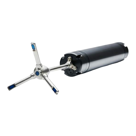
The probe is made of titanium and consists of four receive transducers and
a transmit transducer. It is mounted either on a fixed stem connected to the
main housing through the probe end bell, or on a cable connected to the
main housing through the same probe end bell.
Transducers
Each of the four receive transducers is mounted inside a receiver arm. The
transmit transducer is in the centre of the probe. The transducers are
covered with hard epoxy.
Electronics Modules
The electronics module is located inside the pressure case and consists of a
single board with the power transmitter, analog and digital signal
processing, power conditioning, and interface circuits.
Temperature sensor
The temperature sensor (thermistor) is located inside the probe head.

14 Chapter 3
Technical Description
The two available connectors
Pin
No.
Function
1 A Analog out 1
2 B Analog out 2
3 C Analog out 3
4 D Analog out 4
5 E Gnd (analog)
6 F Sync–
7 G Sync+
8 H Gnd (digital)
9 J Tx
10 K Rx
11 L Gnd (power –)
12 M Power + (15–48V)
The pin-outs for the connectors.
Power and Communication Cable
The power and communication cable is connected to the end bell con-
nector. The cable supplies external DC power (15–48 V) and provides two-
way serial communication with an external computer. It also provides four
analog outputs (0-5 V DC) for input to an AD converter.
The cable also provides synchronization options when the Vectrino is used
as master or slave to synchronize measurements with other Vectrinos
and/or other instruments.
Cable Wiring. By default, the Vectrino is shipped with a 12-pin connector
and cable. The connector type is either a splash-proof connector or an
MCBH-12-FS waterproof connector. The Vectrino power lines are diode
protected, hence, you do not have to worry about wiring the Vectrino
power backwards. If you do, it will not damage your instrument. The pin-
out is shown in the side bar.

Vectrino 15
Chapter 4
Functional Description
This section briefly describes some of the underlying principles that control
the operation and application of the Vectrino velocimeter.
The Vectrino has two modes of operation:
• Command mode. In command mode the Vectrino is ready to accept
your instructions.
• Data Acquisition Mode. The Vectrino enters data acquisition mode
when you click any of the Start commands (e.g. Start Data Collection)
in the Vectrino software. The Vectrino collects data without interruption.
Doppler Theory
Sound does not reflect from
water, but from particles
suspended in the water. These
particles are typically
suspended sediment or seeding
particles, and move with the
same average speed as the
water. The velocity that is
measured is consequently the
velocity of the water.
The Vectrino uses the Doppler effect to measure current velocity. The
Doppler effect is the change in pitch that is heard when either the source of
a sound or the listener is in motion. When you hear a vehicle with a siren,
the pitch is higher when the vehicle is heading towards you, and lower
when it is going away. The change in pitch tells you how fast the vehicle is
moving.
The Vectrino transmits short pairs of sound pulses, listens to their echoes,
and, ultimately, measures the change in pitch or frequency of the returned
sound.

16 Chapter 4
Functional Description
The Vectrino velocimeter
operating principle: A pulse
is transmitted from the centre
transducer, and the Doppler
shift introduced by the
reflections from particles
suspended in the water, is
picked up by the four
receivers.
Data Handling
The Vectrino software saves data in binary files, which are easily converted
to ASCII format files, using the conversion module in the software.
• The *.hdr file is a self-documented table. Please note that this file
contains a detailed data format description of all files that are
generated.
• The *.dat file contains velocity data at the full sample rate.
ASCII files are easily imported into most spreadsheets and data analysis
programs. For turbulent data analysis, Nortek recommends the use of a
specially developed program, ExploreV. You can learn more about this
program on our web pages: Go to www.nortek-as.com, and click your way
to Products > Software products > ExploreV.

Vectrino 17
Chapter 5
Software
This chapter provides you with basic information about the software,
installation of the software and its configuration. For further information,
about the software, its configuration and use, please see the Help function in
the Vectrino software.
Vectrino software options
The Vectrino software program has been designed to set up and read data
acquired by the Vectrino, and is available in two flavors: Vectrino and
Vectrino
¨
. The latter provides a wider range for some of the settings than the
standard version does.
The Vectrino
¨
firmware allows data collection rates up to 200Hz, significantly
higher than the standard Vectrino firmware which has a performance similar
to that of the standard NDV/ADV®, with a maximum output rate of 25Hz.
With Vectrino
¨
a parallel receiver will provide you with four times as many
samples. The Vectrino
¨
also has a separate echo sounder mode for distance
measurements.
The standard Vectrino application is shipped with the instrument. For more
information about the optional software packages and system integration
options, contact your local Nortek representative or Nortek AS. (See our
contact information in Chapter 11, Further Information and Help.)
For information about soft- and firmware updates, please visit the support
pages on our website regularly.

18 Chapter 5
Software
Installation
Follow these steps to install the software on a computer running Windows:
Insert the memory stick and run the Setup.exe file.
Follow the on-screen instructions. Accept the default settings.
If prompted to restart your computer, do so to finalize the installation.
Configurations
Using the enclosed cables, connect the Vectrino instrument to the power
and the USB port on your computer, and start the Vectrino software.
To configure the settings of your Vectrino, you can either
select Data collection > Load From Instrument to read back the current
settings from the instrument
or
select Data collection > Edit Configuration to load the settings from the
configuration file.
The Configuration dialog box where you can adjust the settings will open.

Vectrino 19
Chapter 6
Mounting Guidelines
Follow these guidelines when you mount your Vectrino.
What to consider
•Make sure that there are no obstructions between the sensor and the
focal point (sampling volume) located about 5 cm from the transducers.
Note: When mounting your
Vectrino, use the recessions to
strap it to the structure. Never
use the probe stem as mounting
point.
•Consider the effects of large objects on the flow itself. A rough rule of
thumb is that objects disturb the flow as far as 10 diameters away from
the object. Flow disturbance is greatest directly downstream in the wake
behind the object.
•All acoustic transducers must be submerged during data collection.
Operating your Vectrino when the transducers are out of water will not
cause any damage, but your data will be meaningless. For side-looking
probes, it is possible to collect 2D-data with only the lower receiver arms
submerged.
•The best quality is achieved if the main flow direction is perpendicular to
the transmit axis. Flow directly into the transmit axis should be avoided.
•Make sure your mounting structure is stable. Small vibrations in the
mount can generate large accelerations in the data.

Other manuals for Vectrino
1
Table of contents
Other Nortek Measuring Instrument manuals

Nortek
Nortek Signature Series User manual

Nortek
Nortek Signature VM User manual

Nortek
Nortek AWAC User manual

Nortek
Nortek Signature55 User manual

Nortek
Nortek Vector User manual

Nortek
Nortek Vectrino User manual

Nortek
Nortek Aquadopp User manual

Nortek
Nortek Scour Monitor User manual

Nortek
Nortek Vector User manual

Nortek
Nortek Aquadopp Profiler User manual
Popular Measuring Instrument manuals by other brands

DATREND Systems
DATREND Systems vPad-IV operating manual

Endress+Hauser
Endress+Hauser Flowphant T DTT31 technical information

YOKOGAWA
YOKOGAWA CW500 user manual

SKC
SKC chek-mate 375 series operating instructions

WIKA
WIKA 230.15 operating instructions

Hanna Instruments
Hanna Instruments HI97719 instruction manual