manuals.online logo
Brands
  1. Home
  2. •
  3. Brands
  4. •
  5. NOVAK
  6. •
  7. Controllers
  8. •
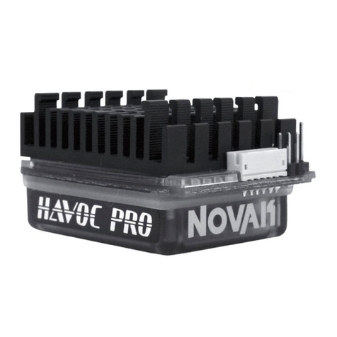
  9. NOVAK HAVOC 3S - GEARING AND ADJUSTABLE PARAMETERS 4-2010... User manual

NOVAK HAVOC 3S - GEARING AND ADJUSTABLE PARAMETERS 4-2010... User manual

With the broad brushless power band, you can go 1-2 teeth higher pinion than listed
above for more top speed, but remember going higher will produce excessive ESC & motor
heating. Check the motor’s operating temperature after making any gearing adjustments-
-motors are designed to operate from 160ºF-175ºF. If you do overheat your ESC and
motor, be sure to allow it to cool for several hours and install a smaller pinion gear.
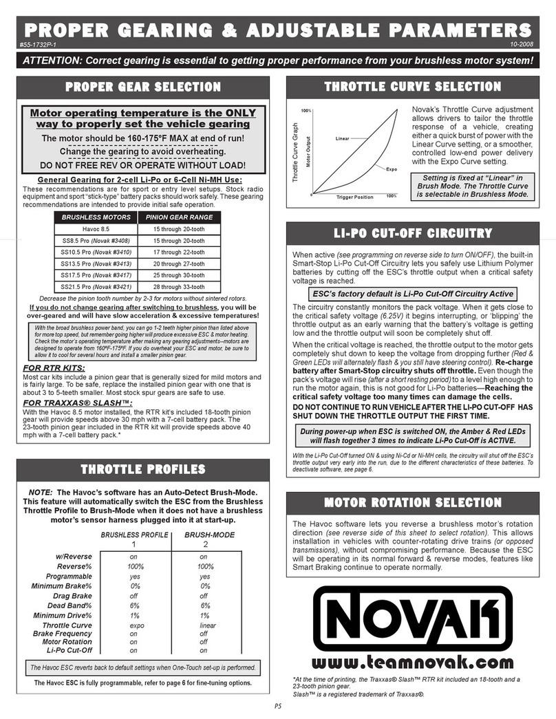
HAVOC 3S GEARING & ADJUSTABLE PARAMETERS
ATTENTION: Correct gearing is essential to getting proper performance from your brushless motor system!
4-2010
#55-1733P-1 Ver. 2
Motor operating temperature is the ONLY
way to properly set the vehicle gearing
The motor should be 160-175°F MAX at end of run!
Change the gearing to avoid overheating.
DO NOT FREE REV OR OPERATE WITHOUT LOAD!
General Gearing for 2 & 3-cell Li-Po or 6 & 9-Cell Ni-MH Use:
These recommendations are for sport or entry level setups. Stock radio equipment
and sport “stick-type” battery packs should work safely. These gearing range
recommendations are intended to provide initial safe operation.
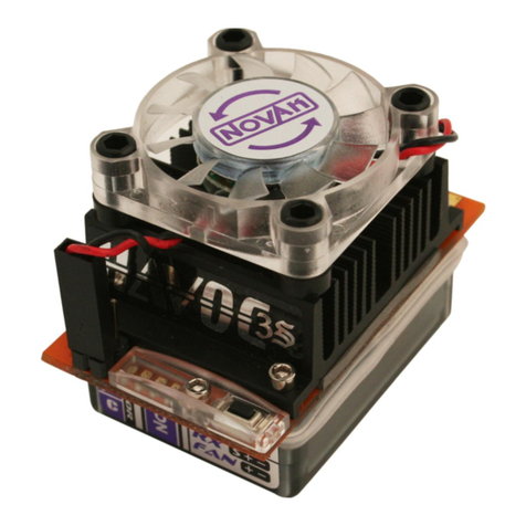
The Havoc 3S’s included fan is required when using a 3S Li-Po battery pack.
Decrease the pinion tooth number by 2-3 for motors without sintered rotors.
If you do not change gearing after switching to brushless, you will be
over-geared and will have slow acceleration & excessive temperatures!
FOR RTR KITS:
Most car kits include a pinion gear that is generally sized for mild motors and is
fairly large. To be safe, replace the installed pinion gear with one that is about 3
to 5-teeth smaller. Most stock spur gears are safe to use.
FOR TRAXXAS® SLASH™:
With a Novak 8.5-turn brushless motor installed, the RTR kit’s included 18-tooth
and 23-tooth pinion gears will provide speeds above 40 mph with various
battery packs. For more specific speed run information and tips to reaching
higher speeds, please visit the Novak Web site.
P5
PROPER GEAR SELECTION
www.teamnovak.com
Motor Output
Trigger Position
0100%
100%
Linear
Expo
Novak’s Throttle Curve adjustment
allows drivers to tailor the throttle
response of a vehicle, creating either
a quick burst of power with the
Linear Curve setting, or a smoother,
controlled low-end power delivery
with the Expo Curve setting.
Setting is fixed at “Linear” in
Brush Mode. The Throttle Curve
is selectable in Brushless Mode.
THROTTLE PROFILES
NOTE: The Havoc 3S has the ability to run on either two or three-cell Li-Po
batteries via Novak’s auto detect software. When Li-Po circuitry is active
(see programming on reverse side to turn ON/OFF), it automatically switches
to the proper Li-Po cut-off voltage for the battery packs you connect.
BRUSHLESS PROFILE
BRUSH-MODE
1 2
w/Reverse
on on
Reverse%
100% 100%
Programmable yes yes
Minimum Brake%
0% 0%
Drag Brake
off off
Dead Band%
6% 6%
Minimum Drive%
1% 1%
Throttle Curve
expo linear
Brake Frequency
4 kHz 3 kHz fixed
Motor
Rotation
CCW Q N/A
Li-Po Cut-Off
on on
The Havoc 3S ESC reverts back to default settings when One-Touch set-up is performed.
The Havoc 3S ESC is fully programmable, refer to page 6 for fine-tuning options.
This ESC is compatible with 2-3S Li-Po or 4-9 Ni-MH cells. Novak’s exclusive
Smart-Stop Li-Po Cut-Off Circuitry is built-in and when active (see program-
ming on reverse side to turn ON/OFF), it automatically switches to the proper
Li-Po cut-off voltage for the battery packs you connect.
ESC’s factory default is ON for Li-Po Cut-Off Circuitry
This circuitry lets you safely use 2S or 3S Lithium Polymer battery packs by
cutting off the speed control’s throttle output when a critical safety voltage
is reached (6.25V for 2S and 9.375V for 3S).
The circuitry constantly monitors the pack voltage. When it gets close to
the critical safety voltage it begins interrupting, or “blipping,” the throttle
output as an early warning that the battery’s voltage is getting low and the
throttle output will soon be completely shut off.
When the critical voltage is reached, the throttle output to the motor gets
completely shut down to keep the voltage from dropping further
(Red & Green
LEDs will alternately flash & you still have steering control)
.
Re-charge battery after Smart-Stop circuitry shuts off throttle.
Even though the pack’s voltage will rise
(after a short resting period)
to a level
high enough to run the motor again, this is not good for Li-Po batteries.
Reaching the critical safety voltage too many times can damage the cells.
DO NOT CONTINUE TO RUN VEHICLE AFTER THE LI-PO CUT-OFF
HAS SHUT DOWN THE THROTTLE OUTPUT FOR THE FIRST TIME.
During power-up when the ESC is switched ON, the Amber & Red LEDs will flash
together 2 times for 2S or 3 times for 3S packs to indicate Li-Po Cut-Off is ACTIVE.
With the Li-Po Cut-Off turned ON & using Ni-Cd or Ni-MH cells, the circuitry will shut off the ESC’s
throttle output, due to the different characteristics of these batteries. To deactivate software, see page 6.
LI-PO DETECT & CUT-OFF
The Havoc 3S software lets you reverse a brushless motor’s rotation
direction
(see reverse side of this sheet to select rotation)
. This allows installation
in vehicles with counter-rotating drive trains
(or opposed transmissions)
,
without compromising
performance. Because the ESC will be operating
in its normal forward & reverse modes, features like Smart Braking
continue to operate normally.
MOTOR ROTATION SELECTION
THROTTLE CURVE SELECTION
Throttle Curve Graph
BRUSHLESS MOTORS PINION GEAR
w/ 2S
PINION GEAR
w/ 3S
Ballistic 8.5 (#3608) / SS8.5 Pro (#3408) 15 – 20-tooth 10 – 15-tooth
Ballistic 10.5 (#3610) / SS10.5 Pro (#3410) 17 – 22-tooth 12 – 17-tooth
Ballistic 13.5 (#3613) / SS13.5 Pro (#3413) 20 – 27-tooth 15 – 22-tooth
Ballistic 17.5 (#3617) / SS17.5 Pro (#3417) 25 – 30-tooth 20 – 25-tooth
Ballistic 21.5 (#3621) / SS21.5 Pro (#3421) 28 – 33-tooth 23 – 28-tooth
*At the time of printing, the Traxxas® Slash™ RTR kit included an 18-tooth and a
23-tooth pinion gear.
Slash™ is a registered trademark of Traxxas®.
if Brushed Mode is
active
P6
1. IF TRANSMITTER IS OFF, DISCONNECT ESC FROM RECEIVER
Remove input signal harness from the receiver to avoid radio interference.
2. CONNECT ESC TO A CHARGED BATTERY PACK
3. SLIDE ESC’s ON/OFF SWITCH TO ‘ON’ POSITION
4. WITH ESC AT NEUTRAL PRESS & HOLD ESC’S SET BUTTON
Release ESC’s SET button once LED is at desired setting.
To skip a parameter, press and hold ESC’s SET button to the desired parameter.
5. SELECT PARAMETER VALUE
LED flashes to indicate active setting (refer to tables at right). Quick press & release
SET button to select desired setting.
6. PRESS & HOLD SET BUTTON TO STORE SELECTION
When SET button is pressed and held for about 1 second, the new selection is
stored in ESC’s memory—The 4 status LEDs will scroll across to indicate ESC is exiting
programming and ESC returns to neutral.
Note: There is no time constraint during selection process of custom parameters.
HAVOC 3S ESC SOFTWARE FLOW CHART
The Havoc 3S ESC features nine parameters that can be adjusted.
Default settings are in bold in tables.
Transmitter can be either ON or OFF:
RESTORING FACTORY DEFAULTS :
Perform One-Touch Set-Up to default ESC back to factory default parameters.
THROTTLE PARAMETER SETTINGS
(Defaults in Bold)
1. MINIMUM BRAKE SETTINGS (10)
BLUE LED
Amount of braking applied with first pulse of transmitter throttle information.
>>Raising this setting starts the braking at a stronger/higher level
.
Setting (# of flashes) 12345678910
Minimum Brake (%):
03 6 9 12 15 18 21 24 27
2. DRAG BRAKE SETTINGS (10)
BLUE & AMBER LEDs
Amount of braking applied while transmitter is at neutral. ‘Coast’ brakes.
>>Raising this setting makes the motor slow down more, without
pushing the transmitter’s trigger into the brake/reverse direction.
Setting (# of flashes) 12345678910
Drag Brake
(%)
:03 6 9 12 15 18 21 24 27
3. DEAD BAND SETTINGS (5)
BLUE & GREEN LEDs
Space between Minimum Brake & Minimum Drive, with neutral in middle.
>>Raising this setting will increase the ‘free play’, or distance your
trigger must move before forward drive or braking will begin.
Setting (# of flashes) 12345
Dead Band
(%)
:23456
4. MINIMUM DRIVE SETTINGS (5)
AMBER LED
Amount of forward drive applied with first pulse of transmitter information.
>>Raising this setting makes the motor start at a stronger/higher
level so it takes off more aggressively from neutral.
Setting (# of flashes) 12345
Minimum Drive (%):
12345
5. THROTTLE CURVE SELECTION* (2)
GREEN LED
>>Changing this setting changes the throttle response and ease of
driveability.
Note: Setting is fixed at “Linear” in Brush Mode.
Setting (# of flashes) 1 2
Throttle Curve
:Linear Expo
6. BRAKE FREQUENCY* (7)
RED LED
>>Raising this setting makes the brake response smoother and
more controllable.
Setting (# of flashes) 1234567
Brake Frequency (KHz):
12345 7.5 8
7. REVERSE* (2)
RED, GREEN & AMBER LEDs
>>Changing this setting activates/deactivates reverse direction.
Setting (# of flashes) 1 2
Reverse (On/Off):
Off (FWD/BRK)
On (FWD/BRK/REV)
8. MOTOR ROTATION* (2)
RED, GREEN & BLUE LEDs
>>Changing this setting changes direction of motor rotation.
Setting (# of flashes) 1 2
Motor Rotation (CCW/CW):
CCW QCW p
9. LI-PO CUT-OFF (2)
RED & AMBER LEDs
>>Changing this setting enables/disables Li-Po cutoff (@6.25 volts).
Setting (# of flashes) 1 2
Li-Po Cut-Off (On/Off):
OFF ON
PLEASE NOTE: This page contains optional Advanced Programming items!
No further adjustments are required.
(But don’t worry, you can always reset factory defaults by performing the One-Touch programming again, so go ahead & experiment—that’s why the programming is in there, right?)
@NEUTRAL
RED LED on solid
MIN. BRAKE
BLUE
press & hold
press & hold
press & hold
press & hold
DRAG BRAKE
BLUE & AMBER
DEAD BAND
BLUE & GREEN
MIN. DRIVE
AMBER
press & hold
THROTTLE CURVE*
GREEN
LEDs roll off
Exit Programming
@NEUTRAL
RED LED on solid
press & hold
BRAKE FREQUENCY*
RED
press & hold
REVERSE*
RED / GREEN / AMBER
press & hold
MOTOR ROTATION*
RED / GREEN / BLUE
press & hold
LI-PO CUT-OFF
RED & AMBER
press & hold
continue holding ESC’s SET button to skip steps here
all LEDs flash
5 times
HAVOC 3S
SOFTWARE
FLOW CHART:
HAVOC 3S ESC CUSTOM PROGRAMMING
*Not adjustable
in brush mode.

This manual suits for next models

1

Other NOVAK Controllers manuals

NOVAK FUSION ESC User manual

NOVAK

NOVAK FUSION ESC User manual

NOVAK 410-M1C User manual

NOVAK

NOVAK 410-M1C User manual

NOVAK DUSTER ESC User manual

NOVAK

NOVAK DUSTER ESC User manual

NOVAK GTB - PROFILE SELECTION & GEARING GUIDE User manual

NOVAK

NOVAK GTB - PROFILE SELECTION & GEARING GUIDE User manual

NOVAK GTB 2 - BASIC SET-UP User manual

NOVAK

NOVAK GTB 2 - BASIC SET-UP User manual

NOVAK GTB RACING BRUSHLESS SYSTEM User manual

NOVAK

NOVAK GTB RACING BRUSHLESS SYSTEM User manual

NOVAK GOAT BRUSHLESS CRAWLER SYSTEM - BASIC SETUP GUIDE... User manual

NOVAK

NOVAK GOAT BRUSHLESS CRAWLER SYSTEM - BASIC SETUP GUIDE... User manual

NOVAK HAVOC PRO SC - TRACK GUIDE User manual

NOVAK

NOVAK HAVOC PRO SC - TRACK GUIDE User manual

NOVAK EXPLORER SPORT User manual

NOVAK

NOVAK EXPLORER SPORT User manual

NOVAK HAVOC SPORT ESC - SETUP GUIDE 2-2009 User manual

NOVAK

NOVAK HAVOC SPORT ESC - SETUP GUIDE 2-2009 User manual

NOVAK GTB - PROFILE SELECTION AND PROPER GEARING User manual

NOVAK

NOVAK GTB - PROFILE SELECTION AND PROPER GEARING User manual

NOVAK GTB BRUSHLESS RACING ESC - 4-2007 User manual

NOVAK

NOVAK GTB BRUSHLESS RACING ESC - 4-2007 User manual

NOVAK T1 User manual

NOVAK

NOVAK T1 User manual

NOVAK CYCLONE User manual

NOVAK

NOVAK CYCLONE User manual

NOVAK GOAT CRAWLER BRUSHLESS SYSTEM User manual

NOVAK

NOVAK GOAT CRAWLER BRUSHLESS SYSTEM User manual

NOVAK ATOM ESC User manual

NOVAK

NOVAK ATOM ESC User manual

NOVAK HAVOC PRO SC - BASIC User manual

NOVAK

NOVAK HAVOC PRO SC - BASIC User manual

NOVAK GTX User manual

NOVAK

NOVAK GTX User manual

NOVAK HAVOC SPORT ESC - BASIC User manual

NOVAK

NOVAK HAVOC SPORT ESC - BASIC User manual

NOVAK M2 DIG - BASIC User manual

NOVAK

NOVAK M2 DIG - BASIC User manual

NOVAK M2 DIG - FIELD GUIDE User manual

NOVAK

NOVAK M2 DIG - FIELD GUIDE User manual

NOVAK 610-RV User manual

NOVAK

NOVAK 610-RV User manual

NOVAK GOAT 3S - BASIC User manual

NOVAK

NOVAK GOAT 3S - BASIC User manual

NOVAK DUSTER II SPORT User manual

NOVAK

NOVAK DUSTER II SPORT User manual

Popular Controllers manuals by other brands

Omron E5AK datasheet

Omron

Omron E5AK datasheet

Franklin BAS-1P Installation & operation guide

Franklin

Franklin BAS-1P Installation & operation guide

Chamberlain LA412UL Wiring diagram

Chamberlain

Chamberlain LA412UL Wiring diagram

AMX NetLinx NI-3000 Dimension Guide

AMX

AMX NetLinx NI-3000 Dimension Guide

Toshiba LC531 Series instruction manual

Toshiba

Toshiba LC531 Series instruction manual

Emerson PACSystems RX3i DNP3 user manual

Emerson

Emerson PACSystems RX3i DNP3 user manual

Happy NG 1.1 Operating	 instruction

Happy

Happy NG 1.1 Operating instruction

Light Stream Controls Auto-Mate/DMX User instructions

Light Stream Controls

Light Stream Controls Auto-Mate/DMX User instructions

Siemens SIMATIC S5-115F user manual

Siemens

Siemens SIMATIC S5-115F user manual

Texas Instruments bq24725A manual

Texas Instruments

Texas Instruments bq24725A manual

Kutai electronics ADVR-16-400HZ Operation manual

Kutai electronics

Kutai electronics ADVR-16-400HZ Operation manual

Toho Electronics TRV1-C015 Operation manual

Toho Electronics

Toho Electronics TRV1-C015 Operation manual

Dynojet Power Commander III installation instructions

Dynojet

Dynojet Power Commander III installation instructions

Lennox V0STAT51P-3 Installation & operation instructions

Lennox

Lennox V0STAT51P-3 Installation & operation instructions

Centork 480 Series TECHNICAL REPORT

Centork

Centork 480 Series TECHNICAL REPORT

Pioneer DDJ-SR Service manual

Pioneer

Pioneer DDJ-SR Service manual

Aventics Emerson AS2-ACD Series RE-ASSEMBLY INSTRUCTIONS

Aventics

Aventics Emerson AS2-ACD Series RE-ASSEMBLY INSTRUCTIONS

Rodix FEEDER CUBE FC-40 Plus Series quick start guide

Rodix

Rodix FEEDER CUBE FC-40 Plus Series quick start guide

manuals.online logo
manuals.online logoBrands
  • About & Mission
  • Contact us
  • Privacy Policy
  • Terms and Conditions

Copyright 2025 Manuals.Online. All Rights Reserved.