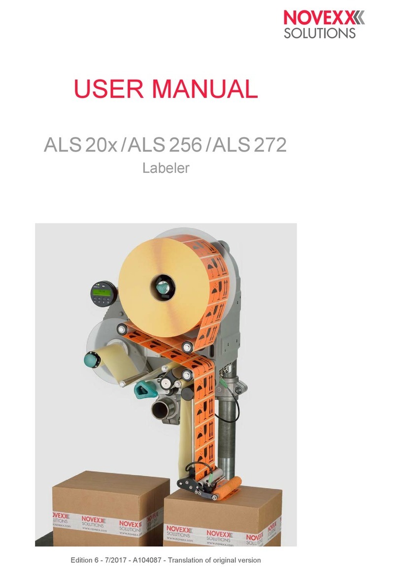
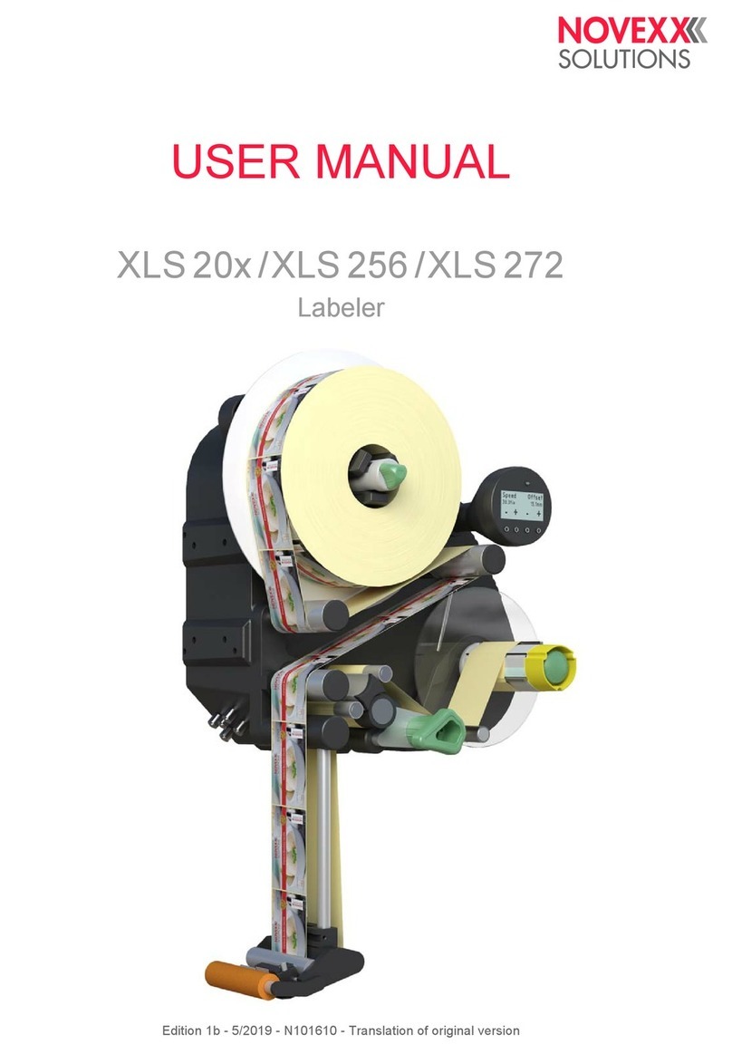
Novexx Solutions ALS/XLS 204 User manual

Edition 9 - 5/2019 - Translation of original version
SERVICE / INSTALLATION
MANUAL
ALS/XLS 20x/256/272
Labeler


Service Manual ALS 20x/256/272
05/2019 3Contents
Contents
Please observe the following -9
General information -9
Validity and applicability of this manual -9
Conventions and information -10
Notes on installation and repair work -11
Safety instructions -15
Information and qualifications -15
Machine operating safety -16
Safe operation -17
Technical Data -19
Technical Data -19
Characteristics -19
Labels -19
Label sensor -20
Power supply -20
Electronics -21
Interfaces -21
Internal Interfaces -22
Status messages, test functions, product profiles -22
Dimensions -22
Ambient conditions -23
Integration -23
Certificates/Markings -23
Dimension diagrams -24
ALS 20x / ALS 256 -24
ALS 272 -26
Performance data -28
Label rate -28
Dispensing speed over duration v(t) -30
Dispensing speed over length v(x) -31
Dispensed label length over duration x(t) -33
(ALS/XLS 256) Performance matrix -34
Installation and Deinstallation -36
Unpacking, assembling and connecting the machine -36
Transport -36
Unpacking -36
Setting up -37
Attaching the dispensing edge -41
Connecting to the mains power supply -43
Connecting the sensors -46
Photoelectric label sensor -46
Alternative label sensor -51
Changing light/dark switching at the product sensor or the alternative label sensor -58

Service Manual ALS 20x/256/272
05/2019 4Contents
Photoelectric product sensor -59
Photoelectric roll diameter sensor -60
Rotary encoder -64
Installing Options -66
Connecting / mounting the external operator panel -66
Mounting a splice table -68
Mounting/connecting the signal beacon -69
Adjustable dispensing edge holder -70
Rotatable dispensing edge holder -71
Narrow label spring kit (ALS/XLS 20x and ALS/XLS 256) -74
Decommissioning, Dismantling, Disposal -76
Take the machine out of operation -76
Dismantling the machine -76
Machine disposal -77
Functions -78
Function menu -78
Overview -78
Notes on the description of functions -80
LABEL SETUP menu -80
MACHINE SETUP menu -82
INTERFACE PARA menu -90
Submenu >EASYPLUGINTERPR -90
Submenu >COM1 PORT -90
Submenu >NETWORK PARAM. -91
SIGNAL INTERFACE -93
Submenu >PLC SIGNALS -93
Submenu >APPLIC. SIGNALS -94
Submenu >AI BOARD SIGNAL -97
Submenu >AI BOARD SIGNAL -98
Submenu >ACTIVE INPUTS -98
SERVICE/DIAGNOS. menu -99
SERVICE DATA menu -100
Submenu >MODULE FW VERS. -100
Submenu >OPERATION DATA -101
Submenu >POWERSUPPLYDATA -101
Submenu >CPU BOARD DATA -102
Submenu >DISPLAY DATA -102
Submenu > PERIPHERAL DATA -103
Submenu >MEMORY DATA -103
Operation -104
Automatic dispensing speed adjustment -104
Principle of operation -104
Mounting the rotary encoder -105
Entering the rotary encoder resolution -106
Entering the diameter of the measuring wheel -106
Service Manual ALS 20x/256/272
05/2019 5Contents
Entering the rotary encoder type -106
Example: Entering the values for the recommended rotary encoder -107
Calibrating the belt speed -107
Calculation scheme for the automatic dispensing speed adjustment -108
Tandem Operation -111
Overview -111
Master operating modes -111
Prerequisites -112
Setting up tandem operation -114
Applicator Operation -121
Function -121
System requirements -121
Assembly and operation -121
Enhanced Functions -122
Access via a Web/FTP server -122
Web server -122
FTP server -126
Loading Firmware -128
Firmware Version -128
Loading from USB stick -129
Download via data interface -130
Loading with the bootloader -132
Saving/loading a configuration -134
Applications -134
Saving onto an external memory medium -134
Loading from an external memory medium -136
Automatic loading -137
Loading a configuration via the data interface -137
Interface commands -142
Command overview -142
Immediately executable commands -143
Not immediately executable commands -146
Forced bootloader start -150
Gen. 1 -150
Gen. 2 -151
Diagnose Dump -152
Storing diagnosis data -152
Reading out via serial interface -152
Storing on memory medium -155
Electronics Description -156
Wiring Diagrams -156
„Gen. 1“-Electronics -156
„Gen. 2“-Electronics -159
Block diagram -162

Service Manual ALS 20x/256/272
05/2019 6Contents
Electronics Components -163
ALS/XLS 20x -163
ALS/XLS 256 -164
ALS/XLS 272 -165
Circuit boards -166
CPU board (Gen. 1) -166
CPU board (Gen. 2) -172
Motor driver board -179
Operator panel board -181
Applicator Interface -184
Power supplies / Transformer -191
Power supply ALS/XLS 20x -191
Transformer ALS/XLS 20x -193
Power supply ALS/XLS 256/272 -193
Signal Interface -195
General notes -195
Circuit diagrams for signal inputs -196
Circuit diagram for signal outputs -197
Signals for applicator connection -197
Applicator type <--> Signals -199
Signal wave forms of applicator signals -200
Signals for PLC connection -209
Signal response „Dispense End“ -210
Impact of the inhibit signal -211
Data interfaces -214
Overview connector positions -214
RS 232 -214
Connection for external operator panel -214
USB (device) -215
USB (host) -215
Ethernet -215
Applicator Interface (option) -218
Important notes -218
Circuit diagrams for signal inputs -218
Circuit diagrams for signal outputs -219
Power outputs -220
Pin assignment for applicator connection -221
Pin assignment for machine status connection -224
Pin assignment for product sensor connection -226
Signal-LEDs -227
Signal wave forms -227
Fault description -228
Types of status messages -228
Error messages -228
Warnings -228
Setting back a warning -228

Service Manual ALS 20x/256/272
05/2019 7Contents
General software errors -229
Machine fails to start -229
Reference of status messages -230
List of warnings -230
List of error messages -231
Repair -242
Tests -242
Sensor test -242
Power Supply ALS/XLS 256/272 -245
Initial state -245
Power supply functions -245
Checking output voltages -246
Troubleshooting -249
Checking the power supply -251
Opening the casing -252
Removing the dust/splash guard (ALS/XLS 20x) -252
Opening the casing at machines held in place by side plate or base plate -253
Opening the casing at machines held from the rear side -255
Overview: Screws holding the casing rear wall -256
(ALS/XLS 256/272) Exchanging the fan -257
Unwind unit -259
Expanding mandrel -259
Brake -261
Dancer arm -263
Feed unit -275
Feed roller unit -275
Drive -281
Pressure roller -285
Rewind unit -288
Expanding mandrel (ALS 2xx) -288
Expanding Mandrel (XLS 2xx) -291
Dancer arm -294
Drive -300
Appendix -302
Additional helpful information -302
Installing a „Generic“ printer on a Windows 7 host PC for the purpose of firmware upload
-302
Settings -305
Setting the capacitive (Leuze) sensor -305
Calculation sheet for performance diagrams -306
Using the calculation sheet -306
Inputs -306
Outputs -307
Diagrams of performance data -307

Service Manual ALS/XLS 20x/256/272
05/2019 | 04 9
Please observe the following
GENERAL INFORMATION
Validity and applicability of this manual
Contents
The present service manual refers exclusively to the labelers:
– ALS 204, ALS 206, ALS 209, ALS 256, ALS 272
– XLS 204, XLS 206, XLS 209, XLS 256, XLS 272
The manual is to be referred to for correct installation, set-up, adjustment and repair of the labelers.
The complete operating manual for the respective labeler consists of the following parts:
Technical State
Technical state: 5/2019
Software versions:
– Firmware: 2.76
– Applicator Interface: 1.44
Liability
NOVEXX Solutions assumes no liability for damages resulting from improper adjustments or
repairs of the machine. It is assumed that only knowledgeable and appropriately qualified persons
are to perform installation, adjustment, or repairs.
Information about the required qualification: see chapter Information and qualifications on
page 15.
Copyright notice
All rights to this operating manual are assigned to NOVEXX Solutions. Transmission, reprinting or
any other means of reproduction of this manual, whether whole or in part, are not allowed without
prior written permission. Third parties, in particular competitors, are not to be allowed access to
information derived from this manual.
Printed in Germany
Manual Target group Medium Availability
User manual Operating personnel Printed Comes with machine
Installation manual Service personnel User Docu-CD
Service manual Service Docu-CD NOVEXX Solutions Partner
Portal: www.novexx.com
Spare parts catalogue

Service Manual ALS/XLS 20x/256/272
05/2019 | 04 10
Manufacturer
Novexx Solutions GmbH
Ohmstraße 3
D - 85386 Eching
Phone: +49-8165-925-0
FAX: +49-8165-925-231
www.novexx.com
Conventions and information
Explanation of symbols
In order to facilitate legibility and an overview, the various types of information used herein are cat-
egorised and identified with certain symbols.
Sentences that are introduced by an arrow contain procedural instructions.
Carry out procedural instructions one after the other in the prescribed order.
The following information is introduced with a dash:
– List items
– Descriptions of conditions
– Description of previous work steps
– Prerequisites for implementing actions described in the following passage
Warnings concerning dangers and risks
Important text passages which must absolutely be followed are particularly marked for special
attention:
Illustrations
When required, text passages are accompanied by illustrations. The illustrations normally show an
ALS 2xx labeler as RH version. XLS 2xx labellers or LH versions are only displayed if differences
need to be highlighted.
The reference to an illustration is indicated by typesetting the [illustration number] in square brack-
ets. Capital letters following an illustration number, e.g. [12A], refer to the corresponding position
indicated in the illustration.
WARNING!
A warning notice indicates risks which could result in death or serious injury of the personnel!
The notice contains safety instructions on how to safeguard possibly affected personnel.
The instructions must be followed.
CAUTION!
A caution notice indicates risks which, if unheeded, could lead to material damage or
bodily injury (minor injuries). The notice contains instructions on how to prevent dam-
age or injury.
The instructions must be followed.

Service Manual ALS/XLS 20x/256/272
05/2019 | 04 11
Symbols for buttons
– Buttons on the operator panel are represented with symbols, as they can be found on (ALS 2xx)
respectively above (XLS 2xx) the buttons. Although the symbols on the control panels of the two
machine series differ slightly, for reasons of clarity only the ALS symbols are used in this man-
ual:
– Where two or more buttons must be pressed at the same time, a "+" appears between the sym-
bols:
+
Functions
Functions are printed in grey text, in the form NAME OF MENU > Name of function .
Supplemental information
The information symbol indicates notices and recommendations as well as additional helpful
information.
Auxiliary materials:
– Auxiliary materials, e.g. lubricants, glues or cleaning agents
Tightening torques:
– Tightening torques for the listed screw connections
If special tools or other aids are needed for a task:
Tools:
– List of the tools and aids that are required for the following activities
Notes on installation and repair work
General information
Before performing any maintenance or repair work:
Block access to the working area of the machine to unauthorised persons.
Post a notification sign, which calls attention to the work.
Electro-static discharge:
When the casing is open, protect the electronics from damage due to electro-static discharge,
e.g. wear an anti-static arm band.
Tools:
Only use suitable tools.
Ensure all tools are at hand before beginning the work.
Do not attempt to improvise or to use improper tools, e.g. loosening an interior-toothed screw
(Torx) with a hexagon socket driver.
Rubber and plastic parts:
Do not allow hoses, seals, and other rubber or plastic parts to come into contact with grease,
petrol, benzene, kerosene or mineral oil.
ALS 2xx
XLS 2xx

Service Manual ALS/XLS 20x/256/272
05/2019 | 04 12
Environmental protection
Avoid unnecessary waste, e.g. use cleaning cloths sparingly and reuse packing material.
Only store operating materials, such as fresh or used cleaning agents, in suitable containers.
Never allow them to enter the sewerage system or to seep into the ground.
Do not put old batteries, removed parts, and used cleaning agents in household waste. Dispose
of them in an eco-friendly manner.
Packaging materials:
– Only recyclable materials are used for packaging the machine.
Dispose of unwanted packaging material in an eco-friendly manner.
Eco-friendly disposal:
Sort the waste as much as possible, e.g. separate metals from plastics.
Avoid contaminating the waste if possible.

Service Manual ALS/XLS 20x/256/272
05/2019 | 04 13
Drop off the waste at the collection points provided for that purpose
or
Have the waste collected by suitable recycling agencies.
Use any on-site options.
Observe all relevant rules, ordinances, and laws.
Rules for electromagnetic compatibility
Connect all metallic parts to each other via large surfaces, ensuring electric conductivity:
– Only polished metal surfaces are electrically conductive. Painted or oxidised surfaces are un-
suitable. Aluminium which appears to be polished still has an invisible oxidation layer on the sur-
face.
– Coated or plated surfaces, though electrically conductive, can reach very high resistance values
at high frequencies (skin effect).
Clean contact surfaces, polish the metal, use fan disks (washers) or mounting plates.
Carry out EMC grounding, preferably as a neutral (star) point. A neutral (star) point prevents
loops.
When laying the signal lines and power cable, space them apart:
Lay all control and signal lines at least 50 cm distant from power cables (e.g. motor line). Mini-
mum distance in the switch cabinet: 20 cm.
Spatially lay out all the lines in the switch cabinet as close as possible to the reference potential.
Lead the signal lines into the unit or switch cabinet from one side only:
– The more lines that are laid in front and in back between the switch cabinet and the machine,
the larger the radiation surface of the radiated electromagnetic energy.
Lead the signal lines out of the machine (in one bundle and from one location, if possible) and
into the switch cabinet.
Twist together unshielded lines from the same circuit:
– This reduces interference effects of various kinds.
Wire inductive components to suitable interference suppressors:
– Possible inductive components: Relay, solenoid valve
– Possible interference suppressors: Diodes, varistors, RC combinations
House all components suspected of being sources of RF interference fields in a closed metal
casing (Faraday screen).
Shield all signal and control lines:
Ground the shielding on both sides at its large surfaces.
For insufficient potential equalisation between the shielding lines: Lay an additional equalisation
lead parallel to the shielding with a cross section at least 10 mm2.
Avoid equalisation currents in the shielding of the signal lines:
– Equalisation currents can arise between subassemblies with different grounding conditions.
When the grounding conditions are different, only shield the side with the better grounding con-
dition.
Only shield both sides when the grounding conditions are the same (e.g. inside a machine).

Service Manual ALS/XLS 20x/256/272
05/2019 | 04 14
Power filter:
Mount the power filter direct at the power supply.
Connect the filter casing to the EMC grounding via large metal surfaces.
Lay all lines as close as possible to metal parts, even reserve cable:
– Freely hanging lines act as transceiver antennas.
Ground all reserve cables and unused wires in the cables at least at one end.
Keep the cables as short as possible:
– Cable resistance and signal distortion increase with the length of the cable.

Service Manual ALS/XLS 20x/256/272
02/2019 | 01 15 Please observe the following
SAFETY INSTRUCTIONS
Information and qualifications
Ensure necessary qualifications
Only allow appropriately qualified personnel to set up, adjust, and repair the labeler, e.g. me-
chanical and electronics specialists.
Only allow work on the electronics system to be done by authorised electronics technicians.
Clearly define the responsibilities for installing, setting up, adjusting, and repairing the labeler.
Consistently adhere to the responsibilities.
Qualification for system integrators and service technicians („service personnel“)
Knowledge required to install the print dispenser and perform service work must be demon-
strated through appropriate qualification. Only service personnel with technical training are
able to assess the tasks to be performed and recognise potential dangers.
– Knowledge acquired through technical training in mechanics and electronics (for example in
Germany the training to become a mechatronics engineer).
– Participation in a technical training course for the corresponding labeler offered by the manufac-
turer.
– The service personnel must be acquainted with the functionality of the labeler.
– The system integrator must be acquainted with the functionality of the of the system into which
the labeler is being integrated.
1) For example faults when detecting labels
2) For example incorrect labelling
Tasks System integrator Operator Service technician
Install the machine X
Connect X
Make settings X
Switch on/off X X X
Insert/change material/ribbon X X X
Application-related settings X X X
Rectify minor operating faults 1XX X
Clean the machine X X
Rectify major operating faults 2X
Settings to the electronics/ mechanics X
Repairs X
Manual: Service manual Operating Manual Service manual, spare
parts catalogue
[tab. 1]An example of the distribution of tasks among different qualified personnel

Service Manual ALS/XLS 20x/256/272
02/2019 | 01 16 Please observe the following
Pay attention to the information
1) Examples: Work place regulation, Accident prevention regulations, Trade union regulations for occupational safety and
health, Equipment safety law, Recycling and waste management law
Information must be made available
This service guide
must be made available to all persons who are entrusted with installing, setting up, adjusting, or
repairing the labeler.
must be maintained in legible condition.
must be made available to the new owner if the machine is sold.
Safety and warning notices attached to the labeler must be kept clean and legible. Missing or
damaged warning plates are to be replaced.
Machine operating safety
Installation, maintenance
WARNING!
Reliable and efficient operation of the labeler is only guaranteed if all necessary information is
observed!
Carry out the installation, connection, programming, setting, and repairing of the machine ex-
clusively in accordance with the specifications in this manual.
Observe additional safety and warning notices attached to the labeler.
Observe and adhere to all relevant ordinances and rules in their applicable form1.
WARNING!
Improper usage of the machine can lead to accidents, material damage and loss of production!
When installing the labeler, check for visible shipment damage. Immediately inform Novexx
Solutions of any damage.
When installing the machine on a support stand, make sure that it can not tip over.
Only put the labeler into operation if it is in flawless condition.
Only perform alterations or conversions to the labeler with the consent of Novexx Solutions's
customer service.
Only use original replacement parts.
Danger of body part trapping and pinching at the dispensing edge due to products moving in the
conveyor direction!
Take appropriate measures to prevent personnel from reaching between a product and the
dispensing edge; e.g. install a protective guard or shield.
Before starting up the machine:
Carry out test runs using the task-specific settings under near production conditions.
Only put the machine into operation after at least one successful test run has been complet-
ed.

Service Manual ALS/XLS 20x/256/272
02/2019 | 01 17 Please observe the following
Protection measures in applicator mode
1) Movable, separating guards according to EN 953
After all servicing or repair work
Safe operation
Protect against injuries that can result from electrical current
WARNING!
Danger of crushing between dispenser edge and applicator pressure plate due to applicator
movement!
Prevent personnel from reaching between dispensing edge and applicator by installing high-
er-level protective equipment 1.
WARNING!
Risk of an accident due to moving or loose parts!
Re-install all covers and safety equipment.
Check for firm seating of all screw connections that were loosened during the work.
Remove all tools and other aids used during service and repair from the working area of the
labeler.
Verify flawless functioning of all safety equipment.
This unit operates at mains voltage! Coming into contact with electrically live components can
cause potentially lethal electrical shocks and burns.
After assembling, check the printer according to the regulations relevant in your country.
WARNING!
Contact with energised components can result in life-endangering currents through the body as
well as burns. The labeler is connected with the mains supply!
Only allow work on the electronics system to be done by authorised electronics technicians.
Observe the following information unconditionally.
Power connection:
If the power switch is not accessible due to the installation position of the machine, a suitable
accessible separator has to be provided by the system integrator.
The device is only completely disconnected from the mains if the power cable is unplugged.
Make sure the power supply socket is accessible.
In case of emergency, switch off the device and disconnect the power cable.
(ALS/XLS 20x with splash guard) The power cable cannot be pulled off from the machine side
power connector .
If the machine is connected to a cabinet, a suitable and accessible power separator must be
provided by the system integrator.

Service Manual ALS/XLS 20x/256/272
02/2019 | 01 18 Please observe the following
Protection against injuries that can result from mechanical actions
Before any repair work:
Detach the machine from power supply.
Check to ensure it is de-energised.
Secure the power supply against unintentional or unauthorised switch-on.
Casing:
Before opening the casing pull the power plug.
The casing may only be opened by trained personnel and when the machine is de-energised.
Only put the machine into operation when the rear wall of the casing is correctly in place.
If the machine must be switched on while the casing is open for repair or inspection:
Never touch energised components. This also applies to components with low voltages.
Ensure the flawless condition of the electrical system:
Regularly check the electrical equipment.
Only connect the machine to other machines if these meet the requirements for a SELV cir-
cuit, in accordance with EN 60950.
Re-tighten loose connections.
Immediately replace damaged lines.
After assembling, check the printer according to the regulations relevant in your country.
WARNING!
Acute risk of injury and long-term bodily injury from working with heavy loads!
Lift or carry the machine with a minimum of 2 persons. If possible, use a crane or other lifting
device.
Only use suitable and defect-free restraining devices during transportation and installation.
Never allow the machine to stand with loosened mounting brackets, not even for a short time.
If the machine is fastened to a movable support: Ensure it can not tip over.
Risk of accident due to uncontrolled machine start-up!
Before doing any repair work, switch off the machine and pull the power plug.

Service Manual ALS/XLS 20x/256/272
05/2019 | 05 19
Technical Data
TECHNICAL DATA
Characteristics
1) The maximum usable dispensing speed depends on the label geometry.
2) At a dispensing speed range of 5 m/min to the max. speed in steps of 10 m/min, see also chapter (ALS/XLS 256)
Performance matrix on page 34.
3) Tested with L-shape dispensing edge on blocks on a conveyor.
4) APSF doesn´t work with pneumatic dispensing edge.
Labels
Dispensing speed 1:
ALS/XLS 204
ALS/XLS 206
ALS/XLS 256
ALS/XLS 209
ALS/XLS 272
max. 40 m/min
max. 30 m/min
max. 50 m/min
max. 25 m/min
max. 70 m/min
Labelling halt precision at the peeling edge:
At fixed dispensing speed 2 ±0.5mm
At variable dispensing speed
ALS/XLS 272
all other machines
±0.5mm
±1mm
Labelling halt precision on the product 3:
At fixed dispensing speed 2
ALS/XLS 272 ±1 mm
Speed control: Fixed setting or automatic speed adaption
(APSF) via rotary encoder 4
Label material: Converted self-adhesive label material with
liner
Internal rewinding yes
Material width (including backing paper)4 :
ALS/XLS 204
ALS/XLS 206
ALS/XLS 256
ALS/XLS 209
ALS/XLS 272
10-110 mm 5
10-160 mm 6
10-160 mm 6
50 -229 mm
10-53 mm 6
Label length: 5 to 1000 mm
Distance between labels on the carrier material: min. 1 mm

Service Manual ALS/XLS 20x/256/272
05/2019 | 05 20
4) Depending on the dispensing edge width.
5) Minimum material width for material with PET liner: 30 mm
6) Minimum material width for material with PET liner: 50 mm
Label sensor
Power supply
7) For more information on fuses, see section Replacing fuses on page 192.
8) Not accessible for user or service technician.
Label roll:
Winding direction
Dispenser (outer) Ø:
Rewinder (outer) Ø:
Core (inner) Ø:
Labels inside or outside
up to 300 mm
up to 200 mm
38.1 / 76.2 / 101.6 mm (1.5 / 3 / 4 ")
Distance to peel edge
L-shape dispensing edge:
V-shape dispensing edge (ALS/XLS 204):
19 mm
77 mm
Sensor type: Transmission sensor; NPN/PNP (switchable)
System voltage:
ALS/XLS 20x
ALS/XLS 256
ALS/XLS 272
110 V (AC) at 60 Hz power frequency
(permissible tolerance ±10%)
230 V (AC) at 50 Hz power frequency
(permissible tolerance ±10%)
100-240 V (AC) at 50-60 Hz power frequency
(permissible tolerance ±10%)
Power consumption:
ALS/XLS 20x
ALS/XLS 256
ALS/XLS 272
max. 460 VA
max. 560 VA
Fuses:
ALS/XLS 20x
ALS/XLS 256
ALS/XLS 272
F1, F2: T5AH 250 V 7
Fuses integrated in the power supply 8
This manual suits for next models
5
Table of contents
Other Novexx Solutions Label Maker manuals

Novexx Solutions
Novexx Solutions 64- series User manual

Novexx Solutions
Novexx Solutions XLP 504 User manual

Novexx Solutions
Novexx Solutions XLP 604 User manual

Novexx Solutions
Novexx Solutions AP 5.4 User manual

Novexx Solutions
Novexx Solutions LA-BO XPA 934 LH User manual

Novexx Solutions
Novexx Solutions ALS 20 series User manual

Novexx Solutions
Novexx Solutions XLP 514 User manual

Novexx Solutions
Novexx Solutions LA-BO Series User manual

Novexx Solutions
Novexx Solutions XLS 20x User manual

Novexx Solutions
Novexx Solutions 64-04 User manual