Novy 800996 User manual

NL Gebruiksaanwijzing p. 2
FR Mode d’emploi p. 2
DE Bedienungsanleitung S. 3
EN User manual p. 3
800996 110132 MA1
Novy
800996
n
✓Mini pure’line
NL
1 VOORSCHRIFTEN VOOR VEILIGHEID EN
MONTAGE
Meer informatie over de Novy producten, accessoires en
diensten kunt u vinden op internet:
− België: www.novy.be
− Nederland: www.novynederland.nl
Dit is de montage instructie voor het toestel zoals op de
voorzijde is aangegeven.
In deze montage instructie wordt gewerkt met een aantal
symbolen. Hieronder vind u de betekenis van deze symbolen.
Symbool Betekenis Actie
Indicatie Toelichting van een
indicatie op het toestel.
Info/
Waarschuwing
Dit symbool duidt op
een belangrijke tip of een
gevaarlijke situatie
Waarschuwing voorafgaand montage
− Lees aandachtig de gebruiksaanwijzing en de montage
instructie vóór de installatie en ingebruikname van dit
toestel. Hierin vind u belangrijke informatie voor de mon-
tage en gebruik van het toestel.
− Controleer aan de hand van de tekening of alle monta-
gematerialen meegeleverd zijn.
−
Het toestel is uitsluitend bedoeld voor huishoudelijk ge-
bruik (bereiding van voedingsmiddelen) met uitsluiting
van alle ander huishoudelijk, commercieel of industrieel
gebruik. Gebruik het toestel niet buitenshuis.
− Bewaar deze handleiding zorgvuldig en geef deze door
aan de persoon die het toestel eventueel na u gebruikt.
−
Dit toestel voldoet aan de geldende veiligheidsvoorschrif-
ten. Ondeskundige montage kan echter persoonlijk letsel
en schade aan het toestel veroorzaken.
−
Controleer de staat van het toestel en het montage-
materiaal zodra u ze uit de verpakking haalt. Neem het
toestel met zorg uit de verpakking. Gebruik geen scherpe
messen om de verpakking te openen.
−
Installeer het toestel niet indien het beschadigd is en
richt u in dat geval tot Novy.
−
Novy is niet aansprakelijk voor schade als gevolg van
onjuiste montage, onjuiste aansluiting, onjuist gebruik
of onjuiste bediening.
− Het toestel niet ombouwen of wijzigen.
−
Metalen onderdelen kunnen scherpe kantjes hebben
en u kunt zich eraan verwonden. Draag daarom bij het
monteren handschoenen die u daartegen beschermen.
FR
1 PRESCRIPTIONS DE SÉCURITÉ ET
D’INSTALLATION
Vous trouverez plus d’informations sur les produits, acces-
soires et services Novy sur Internet : www.novy.fr
Ceci est la notice de montage de l’appareil identifié en
première page.
Cette notice de montage utilise un certain nombre de
symboles. Vous trouverez ci-dessous la signification de
ces symboles.
Symbole Signification Action
Indication Explication d’une indication
apparaissant sur l’appareil
Avertissement Ce symbole signale un
conseil important ou une
situation dangereuse
Avertissements préalables au montage
− Veuillez lire attentivement le mode d’emploi et la notice
de montage avant d’installer et de mettre en service cet
appareil. Vous y trouverez des informations importantes
pour le montage et l’utilisation de l’appareil.
−
Vérifiez sur base du schéma que tout le matériel de
montage est inclus.
−
L’appareil est exclusivement destiné à un usage domes-
tique (préparation d’aliments), à l’exclusion de tout autre
usage domestique, commercial ou industriel. N’utilisez
pas l’appareil en extérieur.
−
Conservez soigneusement cette notice et remettez-le
à la personne qui pourrait utiliser l’appareil après vous.
−
Cet appareil est conforme aux règles de sécurité en vigueur.
Toutefois, une utilisation non conforme peut entraîner
des blessures corporelles et endommager l’appareil.
−
Vérifiez l’état de l’appareil et du matériel de montage dès
que vous les sortez de l’emballage. Retirez l’appareil de
l’emballage avec précaution. N’utilisez pas de couteaux
pointus pour ouvrir l’emballage.
−
Si l’appareil est endommagé, ne l’installez pas et contac-
tez Novy.
−
Novy n’est pas responsable des dommages résultant
d’un montage, d’un raccordement, d’une utilisation ou
d’un maniement incorrects.
− Ne pas transformer ni modifier l’appareil.
−
Les pièces métalliques peuvent présenter des arêtes
vives et peuvent occasionner des blessures. Dès
lors, portez des gants qui vous en préservent lors
de l’assemblage.
– 2 –
EN
1 INSTRUCTIONS FOR SAFETY AND USE
Further information on Novy products, accessories and
services may be found on the internet: www.novy.co.uk
These are the installation instructions for the appliance
shown on the front.
These directions for use make use of a number of symbols.
The meanings of the symbols are shown below.
Symbol Meaning Action
Indication Explanation of an indication on
the device.
Warning This symbol indicates an
important tip or a dangerous
situation
Warnings before installation
− Read the directions for use and the installation instruc-
tions before installing and using this appliance. You will
find important information here for the assembly and
use of the appliance.
− Check on the basis of the drawing that all the materials
for installation have been supplied.
−
The appliance is intended exclusively for household use
(preparation of food) and excludes all other domestic,
commercial or industrial use. Do not use the appliance
outside.
−
Keep good care of this manual and pass it on to any
person who may use the appliance after you.
− This appliance complies with the applicable safety in-
structions. However, inexpert installation may cause
personal injury or damage to the appliance.
−
Check the condition of the appliance and the installation
fittings as soon as you remove them from the packaging.
Remove the appliance from the packaging with care. Do
not use sharp knives to open the packaging.
− Do not install the appliance if it is damaged, and in that
case inform Novy.
−
Novy is not liable for damage resulting from incorrect
assembly, incorrect connection, incorrect use or incorrect
operation.
− Do not convert or alter the appliance.
− Metal parts may have sharp edges, and you may injure
yourself on them. For that reason, wear protective gloves
during installation.
DE
1 SICHERHEITS- UND
MONTAGEVORSCHRIFTEN
Weitere Informationen zu den Produkten, dem Zubehör
und den Dienstleistungen von Novy finden Sie im Internet
unter: www.novy-dunsthauben.de
Diese Broschüre enthält die Montageanleitung für das
Gerät, wie auf der Vorderseite angegeben.
In dieser Montageanleitung werden einige Symbole ver-
wendet. Nachfolgend finden Sie eine Erklärung dieser
Symbole.
Symbol Bedeutung Aktion
Anzeige Erläuterung einer Anzeige auf
dem Gerät
Warnhin-
weis
Dieses Symbol weist auf
einen wichtigen Tipp oder
eine gefährliche Situation hin.
Warnhinweise vor der montage
−
Lesen Sie die Gebrauchsanweisung und Montageanleitung
sorgfältig durch, bevor Sie dieses Gerät installieren und
in Betrieb nehmen. Darin sind wichtige Informationen in
Bezug auf die Installation und Verwendung des Geräts
enthalten.
−
Überprüfen Sie anhand der Zeichnung, ob alle Montage-
materialien vorhanden sind.
−
Das Gerät ist nur für den Hausgebrauch (Zubereitung von
Lebensmitteln) bestimmt, unter Ausschluss aller anderen
haushaltlichen, gewerblichen und industriellen Zwecke.
Das Gerät darf nicht im Freien verwendet werden.
− Bewahren Sie diese Anleitung sorgfältig auf und geben
Sie sie an die Person weiter, die das Gerät möglicher-
weise nach Ihnen benutzt.
−
Dieses Gerät erfüllt die geltenden Sicherheitsvorschriften.
Eine unsachgemäße Montage kann jedoch zu Verletzun-
gen und Schäden am Gerät führen.
−
Überprüfen Sie den Zustand des Geräts und des Monta-
gematerials, sobald Sie es aus der Verpackung nehmen.
Nehmen Sie das Gerät sorgfältig aus der Verpackung.
Verwenden Sie zum Öffnen der Verpackung keine schar-
fen Messer.
−
Installieren Sie das Gerät nicht, wenn es beschädigt ist,
und wenden Sie sich in diesem Fall an Novy.
− Novy haftet nicht für Schäden, die durch falsche Mon-
tage, falschen Anschluss, unsachgemäße Verwendung
oder falsche Bedienung entstehen.
− Das Gerät darf nicht umgebaut oder verändert werden.
−
Metallteile können scharfe Kanten haben, an denen
Sie sich verletzen können. Tragen Sie bei der Montage
Handschuhe, die Sie vor Verletzungen schützen.
– 3 –
4
2
1
NL
Zorg dat de muur waar
tegen de motorunit gemon-
teerd wordt over voldoende
draagkracht beschikt.
De motorunit dient
binnenshuis gemonteerd te
worden.
LET OP! De as van de
motor horizontaal houden.
BELANGRIJK: Lees
a.u.b. de veiligheid en de
installatie instructies van uw
afzuigkap voordat u begint.
DU
Achten Sie darauf, dass
die Mauer, an der die Motor-
einheit montiert werden soll,
eine ausreichende Tragfähig-
keit aufweist.
Die Motoreinheit muss
im Innenbereich montiert
werden.
ACHTUNG! Halten Sie
die Motorachse horizontal.
WICHTIG: Bitte lesen
Sie die Sicherheits- und Ins-
tallationsanweisungen Ihrer
Dunstabzugshaube, bevor Sie
beginnen.
FR
Assurez-vous que le
mur contre lequel le bloc mo-
teur sera monté possède une
capacité portante suffisante.
Le bloc moteur doit être
monté à l’intérieur de l’habi-
tation.
ATTENTION ! Maintenez
l’arbre du moteur en position
horizontale.
IMPORTANT : Veuil-
lez lire les instructions de
sécurité et d’installation de
votre hotte aspirante avant de
commencer.
EN
Make sure that the wall
against which the motor unit
is installed has sufficient load
bearing capacity.
The motor unit must be
installed in-house.
ATTENTION! Keep the
motor shaft horizontal.
IMPORTANT: Please
read the safety and installa-
tion instructions of your
cooker hood before starting.
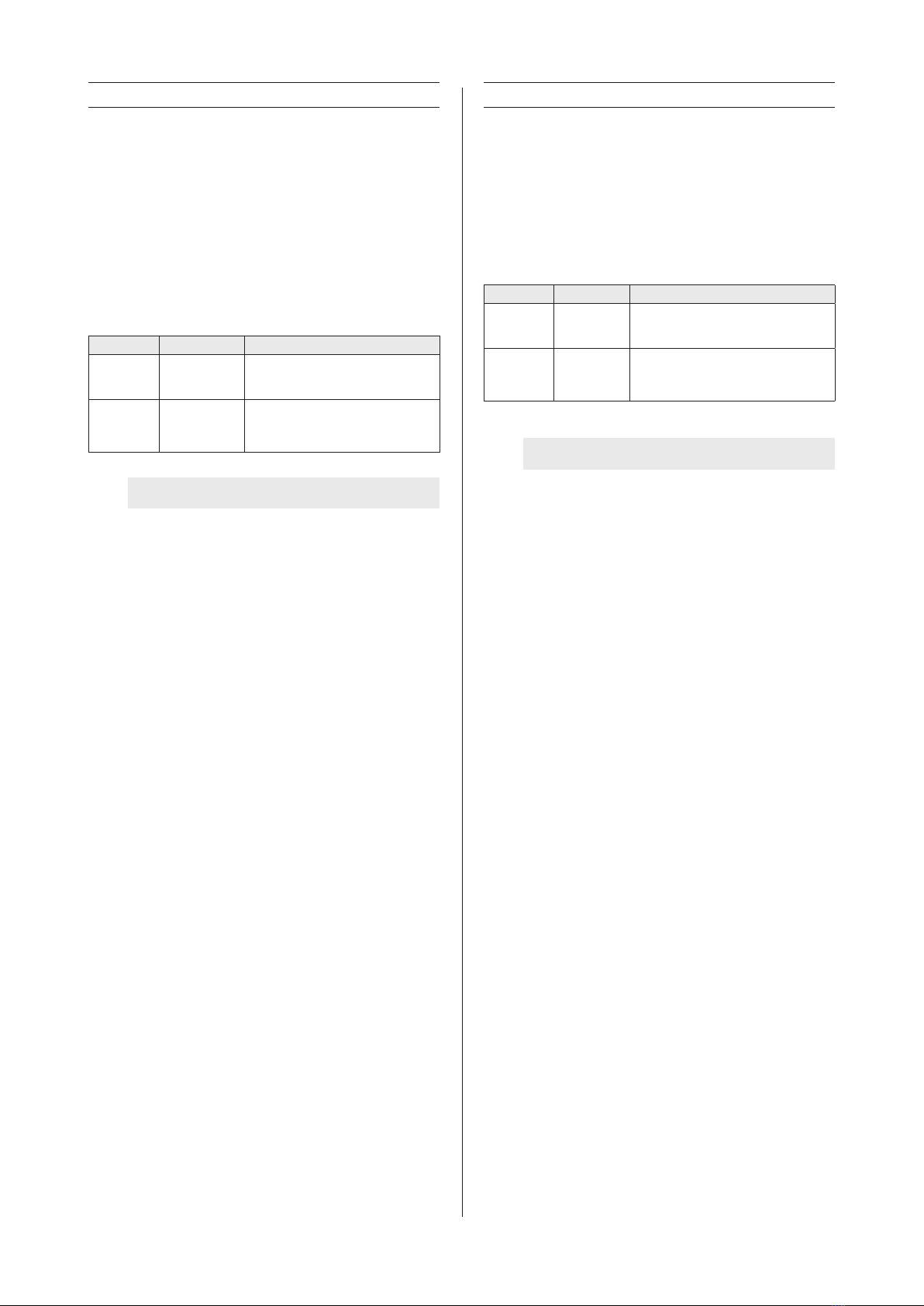
1x 801006
6x 906192 2x 830822 4x 906055 + 906143
1x 906075 1x 990396 8x 906116
2x 820828
810/811/816/820/821/826 ≥V18
3
4x
4x
NL 2 INSTALLATIE
1De motor van de inbouwunit demonteren.
• Open de onderplaat en neem het vetfilter uit de
inbouwunit. Indien een recirculatieffilter aanwezig
is, verwijder deze ook.
• Verwijder de schroeven van de motorunit die zich
naast het afschermraster bevinden. De motorunit
is nu losgekoppeld.
2
Schroef de flensplaat 820828 vast aan de motorunit
met 4 van de meegeleverde schroeven 906116.
3
Schroef de andere flensplaat vast aan de inbouwunit
820828. Gebruik de meegeleverde isolatiestrip 801006
door deze aan de onderzijde van de flensplaat te
plakken. Gebruik de 4 schroeven 906126 om de
flensplaat te monteren op de inbouwunit.
DU 2 INSTALLATION
1
Demontieren Sie die Motoreinheit von dem
Lüfterbaustein.
• Öffnen Sie die Grundplatte und entfernen Sie
den Fettfilter. Auch ein eventuell vorhandener
Rezirkulationsfilter muss entfernt werden.
• Lösen Sie die neben dem Schutzgitter befindlichen
Schrauben. Die Motoreinheit ist jetzt von der
Dunstabzugshaube getrennt.
2Schrauben Sie die Flanschplatte 820828 mit 4 der
mitgelieferten Schrauben 906116 an der Motoreinheit
fest.
3
Schrauben Sie die andere Flanschplatte an
der Einbaueinheit fest 820828. Kleben Sie die
mitgelieferte Isolierleiste 801006 an die Unterseite der
Flanschplatte. Befestigen Sie die Flanschplatte mithilfe
der 4 Schrauben 906116 an dem Lüfterbaustein.
FR 2 INSTALLATION
1
Demontage du bloc moteur du groupe encastrable.
• Ouvrez la plaque inférieure et retirez le filtre à
graisses. Si l’appareil est équipé d’un filtre de
recirculation, retirez-le également.
• Dévissez les vis qui se trouvent à côté de la grille
de protection. Le bloc moteur est maintenant
déconnecté de la hotte aspirante.
2
Fixez la plaque bridee 820828 contre le bloc moteur
a l’aide des 4 vis fournies 906116).
3
Vissez l’autre plaque bridee contre le groupe
encastrable 820828. Utilisez le ruban isolant fourni
801006 en le collant au bas de plaque bridee. Utilisez
les 4 vis 906116 pour monter la plaque bridee sur
le groupe encastrable.
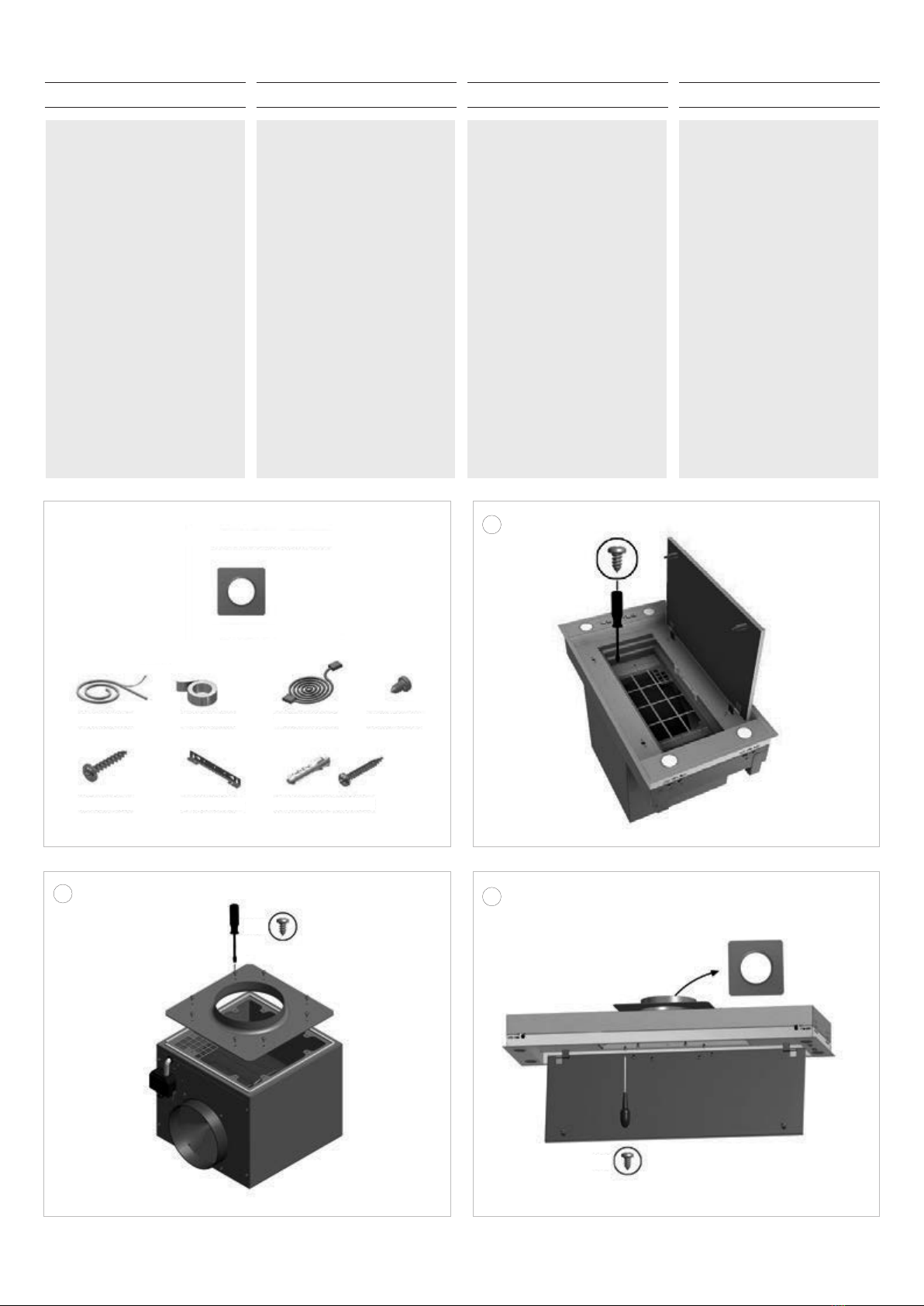
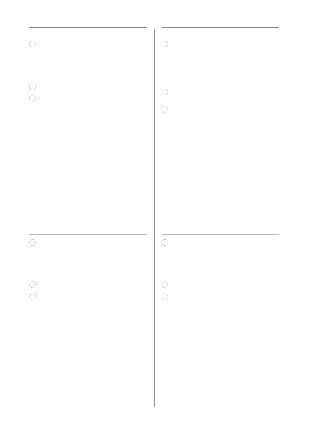
EN 2 INSTALLATION
1Uninstall the motor unit of the built-in unit.
• Open the bottom plate and remove the grease
filter. If a recirculation filter is present, remove it
also.
• Loosen the screws located next to the protective
grid. The motor unit is now disconnected from the
cooker hood.
2Screw the flange plate 820828 onto the motor unit
with 4 of the supplied screws 906116.
3Screw the other flange plate onto the build-in unit
820828. Use the insulation strip 801006 by sticking
it onto the bottom side of the flange plate. Use the
4 screws 906116 to install the flange plate onto the
build-in unit.
– 5 –
6
4
6
5
7
NL
Monteer de inbouwunit
in de uitsparing zoals be-
schreven wordt in de montage
instructie van de betreffende
inbouwunit.
DU
Montieren Sie den
Lüfterbaustein in der Aus-
sparung, wie in der Installa-
tionsanleitung des jeweiligen
Lüfterbausteins beschrieben.
FR
Montez le groupe
encastrable dans la niche
comme décrit dans les
instructions d’installation
du groupe encastrable en
question.
EN
Mount the built-in unit
in the recess as described in
the installation instructions of
the concerned built-in unit.
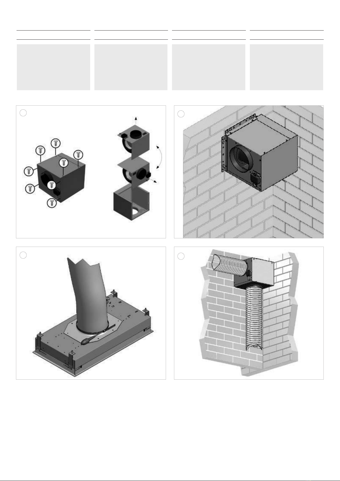
NL
4
Bepaal de plaats waar u de motorunit wilt plaatsen/
ophangen. Indien nodig kan de uitblaasrichting van
de motorunit gewijzigd worden d.m.v. 8 schroeven
van de motordeksel te verwijderen en de motordeksel
een kwartslag draaien.
Voor het bevestigen van de 2 beugels 830822
verwijder de schroeven van het motordeksel aan
de zijde waar de u de ophangbeugels geplaatst
wilt hebben. Bevestig de ophangbeugels aan de
motorunit met de originele schroeven.
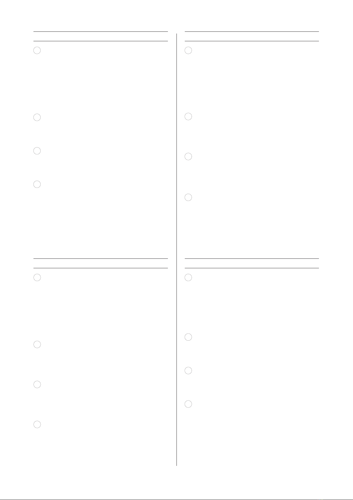
5
Monteer de motorunit aan de muur. Let op, niet
de motor aan het plafond bevestigen. Gebruik
hiervoor de meegeleverde schroeven en eventueel
de pluggen. De aan- en afvoer kunnen in een hoek
van 90° of in een rechte lijn gemaakt worden.
6Gebruik bij alle modellen afzuigkappen een kanaal
van Ø150mm tussen de inbouwunit en de motorunit.
Bevestig het afvoerkanaal aan de flensplaat op de
inbouwunit en op de motor m.b.v. een slangklem
of aluminium tape.
7
Verbind de meegeleverde kabel (990396 tussen de
inbouwunit en de motor d.m.v. de connectoren.
De lengte van deze kabel is 5 m. Optioneel kunt u
een verlengkabel van 5m erbij bestellen (7000094),
zodat de totale lengte van de kabel 10m wordt.
DU
4
Legen Sie die Stelle fest, an der Sie die Motoreinheit
angeordnet/aufgehängt werden soll. Falls erforderlich,
kann die Ausblasrichtung der Motoreinheit geändert
werden, indem 8 Schrauben von dem Motordeckel
entfernt und der Motordeckel um eine Vierteldrehung
gedreht wird. Entfernen Sie zum Befestigen der 2
Bügel 830822 die Schrauben des Motordeckels auf
der Seite, an der Sie die Aufhängebügel platzieren
möchten. Befestigen Sie die Aufhängebügel mit
den Originalschrauben an der Motoreinheit.
5Montieren Sie jetzt die Motoreinheit an der Wand.
Achten Sie darauf, den Motor nicht an der Decke zu
befestigen. Benutzen Sie hierfür die mitgelieferten
Schrauben und ggf. die Dübel. Zuleitung und Ableitung
können in einem Winkel von 90° oder in gerader
Linie vorgesehen werden.
6
Benutzen Sie bei allen Dunstabzugshauben-Modellen
einen Kanal mit Ø150 mm zwischen der Einbaueinheit
und der Motoreinheit.
Befestigen Sie den Abluftkanal an der Flanschplatte
der Einbaueinheit und der Motoreinheit mithilfe einer
Schlauchklemme oder eines Aluminium-Klebebands.
7
Verbinden Sie das mitgelieferte Kabel (990396)
zwischen der Einbaueinheit und der Motoreinheit
mithilfe der Konnektoren. Die Länge dieses Kabels
beträgt 5 m. Optional können Sie zusätzlich ein
5-m-Verlängerungskabel (7000094) bestellen, so
dass das Kabel dann insgesamt eine Länge von
10 m hat.
FR
4
Déterminez l’endroit où vous voulez placer/suspendre
le bloc moteur. Vous pouvez, si besoin est, modifier
le sens de soufflage du bloc moteur en retirant les
8 vis du couvercle du moteur puis en tournant ce
couvercle d’un quart de tour.
Pour fixer les 2 étriers 830822, retirez les vis du
couvercle du moteur du côté où vous souhaitez
placer les étriers de suspension. Fixez les étriers
de suspensions contre le bloc moteur à l’aides des
vis d’origine.
5
Montez le bloc moteur contre le mur. Attention,
ne pas fixer le moteur contre le plafond. Pour ce
faire, utilisez les vis fournies et éventuellement les
chevilles. L’admission et l’évacuation peuvent être
réalisées sous un angle de 90° ou dans une ligne
droite.
6
Pour tous les modèles de hottes, utilisez un conduit
de de Ø150 mm entre le groupe encastrable et le
bloc moteur. Fixez le conduit d’évacuation contre
la plaque bridée sur le groupe encastrable et le
bloc moteur à l’aide un collier de serrage ou d’un
ruban adhésif en aluminium.
7
Raccordez le câble fourni (990396) entre le groupe
encastrable et le bloc moteur à l’aide des connecteurs.
La longueur de ce câble est de 5 m. En option, vous
pouvez commander un câble prolongateur de 5 m
(7000094) pour que la longueur totale du câble soit
de 10 m.
EN
4
Determine the place where you want to place/hang
the motor unit. If necessary, the exhaust direction
of the motor unit can be changed by removing 8
screws from the motor cover and turning the motor
cover a quarter turn. Before fastening the 2 brackets
830822, remove the screws of the motor cover on
the side on which you want the suspension brackets
to be placed. Attach the suspensions brackets onto
the motor unit using the original screws.
5
Install the motor unit onto the wall. Attention! Do
not attach the motor to the ceiling. For this use the
supplied screws and any plugs, if necessary. The
supply and exhaust pipes can be made in a 90°
angle or in a straight line.
6
Use for all hood models a duct of Ø150 mm between
the built-in unit and the motor unit. Attach the
exhaust duct to the flange plate on the build-in
unit and on the motor unit using a hose clamp or
aluminium tape.
7
Connect the supplied cable (990396) between
the build-in unit and the motor unit using the
connectors. The length of this cable is 5 m.
Optional, you can order an extra extension cable
(7000094) , resulting in a total cable length of
10 m.
– 7 –

NOVY nv behoudt zich het recht voor te allen tijde en zonder voorbehoud de constructie en de prijzen van haar producten te wijzigen.
NOVYSA se réserve le droit de modifier à tout moment et sans réserve la fabrication et les prix de ses produits.
Die NOVY AG behält sich das Recht vor, zu jeder Zeit und ohne Vorbehalt die Konstruktion und die Preise ihrer Produkte zu ändern.
NOVY nv reserves the right at any time and without reservation to change the structure and the prices of its products.
NOVY nv
Noordlaan 6
B - 8520 KUURNE
Tel. 056/36.51.00
Fax 056/35.32.51
E-mail: novy@novy.be
http://www.novy.be
France: Tél: 0320.940662
Deutschland und Österreich: Tel: +49 (0)511.54.20.771
Nederland: Tel.: +31 (0)88-0119110
United Kingdom: +44 (0)207 866 2493
España: Tel.: +34 938 700 895
Italia: Tel.: +39 039.20.57.501
Table of contents
Other Novy Ventilation Hood manuals


Novy
Novy 780 Fusion+ User manual

Novy
Novy Flat'line 7600 User manual

Novy
Novy Salsa User manual

Novy
Novy 1801 User manual

Novy
Novy Panorama 1821 User manual

Novy
Novy 7211/15 User manual

Novy
Novy 828 User manual

Novy
Novy Pureline Pro 6930 User manual

Novy
Novy 7811/2 User manual

Novy
Novy Panorama Pro User manual


Popular Ventilation Hood manuals by other brands

Franke
Franke FTLN I H45 X/BK installation manual

Greenheck
Greenheck SP Installation, operation and maintenance manual

Atag
Atag mistral Instructions for use

Bosch
Bosch DFS097E50A Instructions for installation and use

Miele
Miele DA 399-5 EXT Operating and installation instructions

ETNA
ETNA AP160RVS Instructions for use


