NSS WRANGLER 2016 AB User manual

OPERATION MANUAL
WRANGLER 2016 AB
WRANGLER 2016 DB
Original Instructions
Instructions D'origine
https://harrissupplyind.com-ToOrderPartsCall608-268-8080

OPERATION MANUAL
WRANGLER 2016 AB
WRANGLER 2016 DB
IMPORTANT SAFETY INSTRUCTIONS
WARNING: Failure to observe these instructions can cause
personal injury to machine operator or bystanders.
WARNING: Fire or explosion hazard.
NEVER operate this machine in an
explosive atmosphere (grain dust,
flammable liquids or fumes, etc.).
WARNING: Fire or explosion hazard.
NEVER attempt to pick up flammable or
combustible materials or use such materials
in tank.
WARNING: Orange Oil (D-limonene) is not compatible with the plastics used in NSS
automatic scrubbers and the Sidekick Chemical Metering System. Use of D-limonene may
result in damage to the machine.
WARNING: This product contains a chemical known to the state of California to cause
cancer and birth defects or other reproductive harm.
INTENDED USE
This machine is intended for commercial use,
scrubbing floors in an indoor environment. NSS
does not recommend using this machine for any
other purpose.
FOR SAFETY:
ALWAYS read and understand all instructions
before operating or servicing machine.
ALWAYS use this machine ONLY as described in
this manual.
NEVER attempt to operate this machine unless
you have been trained in its operation.
NEVER allow an untrained person to operate this
machine.
NEVER attempt to operate this machine if it is not
working properly or has been damaged in any
manner.
NEVER disconnect or modify any switches or
safety devices (circuit breaker).
NEVER drop or insert any object into any machine
opening.
NEVER operate this machine with any air opening
blocked. Keep all air openings free of dust, lint,
hair, etc.
NEVER pick up anything that is burning or
smoking, such as cigarettes, matches or hot
ashes.
NEVER spray this machine with water or any
liquids.
NEVER allow the vacuum motor or battery
charging plug to get wet or a short may occur.
NEVER operate this machine when the battery
charger is plugged in.
NEVER operate this machine with the bumper
guard removed.
NEVER allow this machine to be used as a toy.
Close attention is necessary when used by or near
children.
ALWAYS wear clean tennis shoes or “non-slip”
shoes. Leather soled shoes will become extremely
slippery when wet.
ALWAYS keep face, fingers, hair or any other body
part or loose clothing away from any machine
opening or moving part (revolving brush, pad driver,
or vacuum motor).
ALWAYS turn the machine off when attaching pads
or brushes.
ALWAYS remove keys when this machine is left
unattended.
ALWAYS be sure that the ramp is secured to the
vehicle before attempting to load / unload.
ALWAYS use extreme caution when operating the
machine on a ramp or loading / unloading this
machine into or out of a truck / trailer. Use extreme
caution if the ramp is wet, oily, or covered with
cleaning chemicals.
NEVER stop or turn the machine on a ramp or
incline.
NEVER attempt to climb a grade or operate this
machine on a ramp or incline of more than 8 degrees.
NEVER park or store the machine near a dock, on
ramps, near a furnace, boiler, open flame, or other
high heat source.
NEVER allow this machine to freeze.
NEVER expose the machine to rain, snow, or
extreme temperatures.
NEVER store any items on this machine.
ALWAYS store this machine indoors in a dry, cool
area.
SAVE THESE INSTRUCTIONS
ALL REPAIR SERVICE MUST BE PERFORMED BY AN NSS AUTHORIZED DISTRIBUTOR /
SERVICE STATION USING ONLY NSS ORIGINAL EQUIPMENT PARTS.
https://harrissupplyind.com-ToOrderPartsCall608-268-8080

IMPORTANT SAFETY INSTRUCTIONS
BATTERY POWERED EQUIPMENT WITH ON BOARD CHARGERS
WARNING: Failure to observe these instructions can cause personal
injury to machine operator or bystanders.
GENERAL
ALWAYS read and understand all instructions
before installing or charging batteries.
NEVER attempt to install or charge batteries
unless you have been trained to do so.
NEVER allow an untrained person to install or
charge batteries.
ALWAYS remove all jewelry when working on or
near the batteries.
ALWAYS turn off all switches during installation
and service.
ALWAYS disconnect the battery leads before
performing any service or repair.
ALWAYS wear eye protection and protective
clothing to avoid contact with battery acid.
NEVER lay anything on top of batteries as arcing
may occur.
IF CONTACT WITH BATTERY ACID OCCURS,
follow these instructions:
SKIN – rinse area with water.
EYES – Flush with water for 15 minutes.
INTERNAL – Drink water or milk. Follow with
Milk of Magnesia, beaten egg or vegetable
oil. Call a physician immediately.
BATTERY INSTALLATION
ALWAYS use two people to install, as batteries
are heavy.
ALWAYS position batteries as shown on the
machine installation decal to maintain machine
balance.
ALWAYS connect batteries as shown on the
machine installation decal to avoid shorting out
the batteries and the electrical system.
BATTERY CHARGING
ALWAYS read instructions on charger carefully.
ALWAYS use the NSS supplied charger with proper
voltage rating.
For flooded lead acid batteries only (does not apply to
AGM or Gel cell batteries):
ALWAYS check to ensure the battery water level covers
the battery plates before charging.
ALWAYS check water level after charging and add
distilled water if necessary to
bring level to the bottom of the fill
hole.
NEVER
overfill batteries as battery
and machine damage may result.
ALWAYS wipe any acid from the top of batteries using a
soap solution.
ALWAYS study battery manufacturers’ specific
precautions such as recommended rates of charge.
ALWAYS reattach caps to batteries. Do not charge with
caps loose or removed.
ADD only distilled water.
For all battery types:
NEVER charge a frozen battery.
ALWAYS plug the charger into an earthed socket -
outlet.
NEVER touch uninsulated portion of output connector or
uninsulated battery terminal.
ALWAYS disconnect the AC supply before making or
breaking the connections to the battery while charging.
NEVER operate charger if the AC supply cord is
damaged or if the charger has received a sharp blow,
been dropped, or otherwise damaged in any way.
ALWAYS keep flammable materials away from charger.
Shock or
electrocution
hazard.
No smoking, open
flames, or sparks while
working with batteries.
Contains acid.
Avoid contact Poison. Causes
severe burns. Avoid
contact.
WARNING: Batteries emit hydrogen, which can cause fire or explosion.
NEVER smoke, light a match, or cause a spark during operation or charging.
ALWAYS char
g
e in a well-ventilated area awa
y
from o
p
en flame.
ALL REPAIR SERVICE MUST BE PERFORMED BY AN NSS AUTHORIZED DISTRIBUTOR/
SERVICE STATION USING ONLY NSS ORIGINAL EQUIPMENT PARTS
SAVE THESE INSTRUCTIONS
Read and understand all
instructions before
installing or charging
batteries.
https://harrissupplyind.com-ToOrderPartsCall608-268-8080

IMPORTANT SAFETY INSTRUCTIONS
GROUNDING OF ELECTRICAL EQUIPMENT - BATTERY CHARGER
WARNING: Improper connection of the equipment–grounding
conductor can result in a risk of electric shock. Check with a qualified
electrician or service person if you are in doubt as to whether the outlet
is properly grounded. Do not modify the plug provided with the
charger. If outlet is not suitable for safe use; have a properly grounded
outlet installed by a qualified electrician.
Always use a properly grounded 3-wire extension cord, which has
male and female plugs. If 25 foot [7.6m] extension cords are used, the
electrical carrying capacity should be no less than 14-3 ST., 50-foot
[15.2m] extension cords no less than 12-3 ST
GROUNDING INSTRUCTIONS
This charger shall be grounded while in use to protect the operator from electric shock. The charger is
provided with a three-conductor cord and a three-contact grounding type attachment plug. The plug must be
plugged into an appropriate outlet that is properly installed and grounded in accordance with all local codes
and ordinances. The green conductor in the cord is the ground wire. Never connect this wire to other than
the grounding pin of the attachment plug.
Check nameplate on the charger to be sure voltage and cycle stated is the same as the electrical outlet. Do
not attempt to plug a 120-volt charger into a 240-volt outlet or a 240-volt charger into a 120-volt outlet. If the
cord provided with the charger has an attachment plug as shown in Figure A. below, it is intended for use on a
nominal 120-volt circuit. If a properly grounded receptacle as shown in Figure A is not available, an adapter
may be installed as shown in Figure B if the outlet box that houses the receptacle is grounded. Be sure to
fasten the grounding tab (the green colored rigid ear, lug or the like extending from the adapter) with a metal
faceplate screw.
If the cord provided with the charger has an attachment plug as shown in Figure C, it is intended for use on a
nominal 240-volt circuit (single phase only). Changes to the attachment plug or use of adaptors to other plug
types must be done in accordance with local regulations.
NOTE: In Canada, the use of a temporary adaptor may not be permitted by Canadian electrical code.
ALL REPAIR SERVICE MUST BE PERFORMED BY AN NSS AUTHORIZED DISTRIBUTOR/
SERVICE STATION USING ONLY NSS ORIGINAL EQUIPMENT PARTS.
SAVE THESE INSTRUCTIONS
https://harrissupplyind.com-ToOrderPartsCall608-268-8080

NOISE AND VIBRATION
MACHINE INSPECTION
Now that the machine is unpacked remember to
recycle all packing materials.
Inspect the machine for damage or missing
components. If damage is found, contact the local
freight company to file a freight claim.
MACHINE COMPONENTS
Solution Tank
The solution tank is the lower part of the machine body
and has a capacity of 16 gal (60.5 L).
The amount of water in the tank is measured in the
plastic tube at the right rear of the tank. The solution
tank is emptied through the clear plastic tube at the
right rear of the tank.
Recovery Tank
The recovery tank is the upper part of the machine body
and has a capacity of 17 gal (64.3 L).
A round clear view lid assembly closes off the
recovery tank’s opening.
The recovery tank has a foam sensitive float shut-off
assembly. As the water level rises, the float ball will
rise into the tube and shut of the airflow of the
vacuum. NOTE: The float shut-off assembly does
not shut off the vacuum motor.
Operator Control Panel
The operator control panel is located at the upper rear
area of the machine. This panel has components that
control various machine functions.
The toggle switch on the left controls the brush motor.
The toggle switch on the right controls the vacuum
motor.
The red button is the master power switch; it controls
the power to all components. Power on, is indicated
by the Battery Meter.
Battery Meter
The battery meter is located on the left side of the
operator control panel and shows the state of charge of
batteries during operation.
The battery meter is equipped with a relay that will
open, turning off the machine, when the battery voltage
has dropped to its lowest permissible level.
When the batteries are fully charged, all of the LED’s
are illuminated.
As the batteries discharge, the LED’s start to turn off,
one at a time, from right to left.
When the last yellow LED on the left starts blinking,
there is only a few minutes of runtime left before the
machine is automatically turned off. NOW is the time
to turn off the brushes and vacuum motor, and drive
to the battery charging area.
If the machine is operated until it is automatically shut
off, turn off the master switch, the brush switch, and
the vacuum switch. Then turn on the master switch,
and the machine can be driven to a charging location
(wheel drive models only).
Circuit Breaker
The circuit breakers are located to the left of the
handle grips.
The right circuit breaker is for the vacuum motor.
The left circuit breaker is for the brush motor.
Wheel Drive models:
The center circuit breaker is for the drive motor.
In the middle of the panel are two (2) rubber twist
grips. These grips rotate forward and backward to
control the direction and speed of the machine. The
farther the grips are rotated, the faster the machine
will move. These twist grips have a feature that
returns the machine to the neutral position when the
handles are released.
Solution Control (Valve) Lever
The solution control lever is located on the left rear
side of the machine. This lever controls the solution
valve and the amounts of liquid put on the floor when
cleaning. Pull up on the handle to open the valve.
Push down on the handle to close the valve. The
control lever can be placed in notches to maintain
desired flow between the open and closed position.
Solution Filter Assembly
Attached to the solution control valve is a canister
strainer designed to stop debris from entering the
solution solenoid valve.
If the solution stops flowing to the brush, close the
solution control valve and unscrew the canister bowl
(by hand), remove and clean the screen.
Battery Compartment Drain Hose
This hose is tucked up under the lower right side of the
control panel. The spilled liquids from the battery
compartment collect in it. A pinch clamp is used to hold
it closed.
Inspect the hose for liquid level on a weekly basis.
Dispose of liquids according to your local and federal
regulations.
Brush Gear Motor
This machine has a 24-volt brush motor located at the
front of the machine. The motor is attached to a
gearbox to turn the pad driver or brush.
The right lift arm is used to raise or lower the brush
motor to and from transport, float, or heavy scrub
positions.
This motor has carbon brushes that must be serviced
on a regular basis. The carbon brushes have an
expected life of 2,000 operating hours. Refer to the
maintenance section later in this book.
Vacuum Motor
This machine has a 24-volt vacuum motor.
The vacuum motor is mounted to the underside of the
recovery (top) tank.
NOISE
Sound pressure level at Operator
position (ISO 11201)
72 dB(A)
VIBRATION
Weighted RMS acceleration value
(ISO 5349)
.575 m/s2
https://harrissupplyind.com-ToOrderPartsCall608-268-8080

This motor has carbon brushes that must be serviced
on a regular basis. The carbon brushes have an
expected life of 700 operating hours.
Wheel Drive models / Drive Motor:
This machine is powered forward and reverse by a 24-
volt drive motor.
The speed is electronically controlled for smooth
increase and decrease in speed.
The motor moves the drive wheels through a gearbox
and transaxle system.
This motor has carbon brushes that must be serviced
on a regular basis. The carbon brushes have an
expected life of 2,000 operating hours.
Squeegee Assembly:
The squeegee assembly is available in both straight
and curved. The straight squeegee uses a dual (2)
Linatex blade system. The “curved” squeegee has a
Linatex rear blade and neoprene front blade.
PREPARING THE MACHINE
Installing the Batteries:
Turn off all switches and tilt the recovery tank open to
expose the battery compartment.
Batteries are heavy - use two people to install.
Refer to the wiring diagram inside the battery
compartment. Align batteries in the compartment as
shown on the diagram.
Install battery cables as shown on the wiring diagram.
Tighten bolts and hex nuts with a wrench.
Warning: Do not short across two terminals with
a wrench. Possible personal injury may occur.
Loose or improper battery connections will cause
battery or machine damage and possible personal
injury.
Charge the batteries before use!
Battery Charging
To recharge the batteries plug the charger cord,
located at the rear of the machine, into an electrical
outlet (100/115/230 50/60HZ VAC).
When the cord is plugged into an outlet the machine
will become disabled.
See Battery Charger section for more details.
Preparing the Solution and Recovery tanks:
Never use water over 140°F (60°C) degrees.
Excessively hot water may damage components such
as the tanks.
Make sure the drain plug of the recovery tank is
closed tightly and in its holding clip.
Put 1 to 2 gallons [3.8 to 7.6 L] of clean water into the
solution tank first to help dilute the chemicals and
prevent excess sudsing. Dilute the cleaning
chemicals according to the manufacturer’s
instructions.
Fill the tank by pouring the water and cleaning
chemicals through the mesh filter that covers the
opening at the front of the solution tank.
Always use a defoamer to protect the vacuum motor.
Consult your local distributor for complete chemical
advice.
Install a pad driver and pad:
There is a wide range of pads or brushes available for
the many cleaning applications of this machine.
Consult your local NSS distributor for application
recommendations.
Turn the pad driver upside down on the floor and
remove the pad holding cup.
Remove the center cutout of the pad. Place the pad
on the face of the pad driver.
The pad must be centered on the driver to prevent
wobbling or bouncing.
Install and secure the pad holding cup to the pad
driver. Turn the pad driver over so that the pad faces
the floor.
Raise the brush motor into the transport position.
Align the slots of the pad driver with the lugs of the
drive casting.
Turn the pad driver until it stops and stays in place.
Install a Brush:
Raise the brush motor into the transport position.
Align the slots of the brush with the lugs on the drive
casting.
Turn the brush until it stops and stays in place.
Install the squeegee assembly:
Place the squeegee lift handle in the storage (up)
position.
The squeegee assembly mounts to a metal bracket at
the rear center of the machine, using two (2)
mounting knobs. Loosen the mounting knobs and
slide the squeegee assembly onto the mounting plate.
The squeegee assembly has two (2) small wheels to
prevent “rollover” while in reverse. The roller wheels
must face the operator. Hand tighten the mounting
knobs. Do not use pliers to tighten knobs, as this will
defeat the “breakaway” design.
Do not add any weights or other pressure to the
squeegee mechanism. This will not improve the
performance and will shorten the life of the blades.
It is recommended that, with new blades, the rear
wheels be adjusted to their lowest position. Loosen
the two screws on the bracket rotate the bracket
downward as far as it will go, then tighten the screws.
Perform this adjustment on both wheels/brackets.
When the squeegee becomes worn, and the wiping
edge no longer contacts the floor properly, further use
may be possible by adjusting the rear wheels upward
enough to restore proper engagement of the blades
wiping edge with the floor. Be sure to adjust the
wheels back down fully when a new blade is installed.
Operating the Machine
The Wrangler 2016 has the brush motor offset to the
right side of the machine. This offset allows you to
clean the edge of a floor or an obstructed area (walls or
shelving) with the right side of the machine.
https://harrissupplyind.com-ToOrderPartsCall608-268-8080

Normal Cleaning:
Sweep and dust mop the floor to remove dirt and
debris before scrubbing. Accumulations of dirt or
debris on the floor will reduce cleaning performance.
You may also need to pre-clean some types of spills
or stains before scrubbing.
Plan your work so that you make long, straight paths
with the fewest amount of turns possible, overlapping
each cleaning path about 2 in. (5 cm.) to prevent
streaking and dirty areas.
Move machine to area to be cleaned.
Place “Wet Floor” warning signs in area.
Turn on master switch.
Turn on vacuum motor switch.
Lower the brush motor and squeegee assembly into
the operating position on the floor.
AB Models - The brush motor is turned on and off
with the brush switch on the control panel.
DB Models - The brush motor will automatically turn
on when moving either forward or backwards.
Lift solution valve handle to start liquid flow to floor.
Adjust amount of flow as needed. Close the solution
valve completely 10 ft (3 m) before you turn at the
end of your cleaning path. This will reduce the
amount of liquid on the floor when you make your
turn.
Reopen the solution valve when starting the next
pass. Repeat this procedure for each pass.
NOTE: Solution will not flow until brush turns on.
Watch the level of liquid in the recovery tank and
listen for the float shut-off to change the sound of the
vacuum motor. When the vacuum airflow stops, you
must turn off the vacuum motor and empty the
recovery tank.
Take the machine to an approved disposal drain and
turn off all switches.
Pull the flexible rubber drain hose out from behind the
brush motor. Raise the end of the hose above the
level of the recovery tank, loosen and remove the
hose drain plug. Carefully direct the drain hose into
the drain.
When the recovery tank is empty, replace and tighten
the drain plug. Place the drain hose back behind the
brush motor. Do not obstruct the lift mechanism or
brush motor.
Special Cleaning
This machine may be used to perform special cleaning
jobs other than “normal” scrubbing.
Double scrubbing
This procedure provides deeper cleaning on heavily
soiled floors. One or more cleaning passes are made
before picking up the chemicals with the squeegee.
This allows dwell time. Best results are achieved by
placing the brush motor in the heavy scrub position.
Caution: The floor surface becomes extremely slippery
in this operation. This machine should be operated only
in slow to medium speed and great care should be
taken when walking on this wet surface.
Stripping:
This procedure is used to remove moderate build-up
of floor finish from the floor. The most aggressive
pads or brushes are used in this procedure.
The stripper solution is applied to the floor with a mop
and then double scrubbed as described above.
Stripping solution should not be put into the solution
tank. Clean water from the solution tank is applied to
the floor to keep the chemicals and finish in a “liquid”
condition. The floor surface becomes extremely
slippery in this operation. This machine should be
operated only in slow to medium speed and great
care should be taken when walking on this wet
surface.
MACHINE MAINTENANCE
Routine maintenance is critical to ensure proper
machine operation and cleaning performance. Perform
all maintenance procedures as follows.
Always turn OFF all machine switches before
performing any maintenance.
Adjusting the squeegee assembly:
Turn the vacuum motor ON and open the water valve
slightly.
Squeegee blades should lie over slightly (like a
window squeegee) when the machine is moving.
If adjustment is required adjust the blade angle by
turning the wing nut on the squeegee mount.
Daily Maintenance
Battery Charging
The master power switch and all other switches
must be turned OFF.
You must recharge the batteries when indicated by
the battery meter, and after every use. Read the
battery meter while the machine is in use.
*235 AH batteries require 8-12 hours to fully charge.
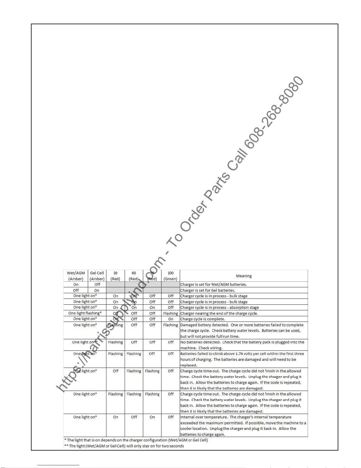
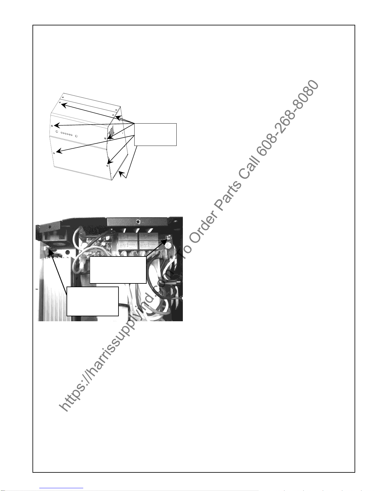
Determine which Battery Charger you have - then see
the Operating Instructions for that Charger.
NSS-Pro Charging: LED’s & metal housing
SPE – digital display and plastic housing.
Battery Electrolyte (liquid) Level (Flooded only)
Inspect the electrolyte level of at least one cell in each
battery before daily charging. The liquid must be visible
above the internal plates. Do not charge the batteries if
the liquid is below the plates.
NEVER let the electrolyte level fall below the tops of
the plates. This will damage the batteries
immediately, and void the warranty.
Add only distilled water to the cell of a battery to adjust
the liquid level. Do not use well or tap water. Before
charging, add only enough water to cover the top of
the internal plates. After charging, add only enough
water to bring the level to the bottom of the fill tube.
Do not overfill the battery liquid, this will cause
electrolyte (acid) spill. Spilled electrolyte (acid) can
cause machine damage and personal injury. Clean
and dispose of spills immediately.
Every cell of every battery must be checked and
replenished (if needed) once per week
https://harrissupplyind.com-ToOrderPartsCall608-268-8080

See the battery-warning sheet (page 3) for more
details.
Battery Packages
The Wrangler 2016 is a 24-volt system and is available
with two battery packages.
Four (4) 6 volt, 235 Amp Hour Batteries – NSS-PCS.
Two (2) 12 volt, 130 Amp Hour Batteries - SPE.
Solution and Recovery Tanks
The recovery tank is emptied through a large rubber
hose at the front of the machine. Remove the plug
and drain the liquids according to your local and
federal regulations.
Every time you empty the recovery tank, we
recommend that you add at least 4 to 6 ounces [120
to 175 mL] of defoamer chemical into the recovery
tank before resuming work. Vacuum the defoamer
into the empty recovery tank through the squeegee
vacuum hose.
At the end of the day empty all liquids from both
solution and recovery tanks. Rinse both tanks with
clean water to prevent chemical residue build-up,
allow to air dry to prevent odors.
Remove any residue from screen and float ball to
ensure proper operation. Replace float assembly in
recovery tank.
Check clear lid for airtight seal.
Check the drain hose for damage.
Inspect and clean the vacuum filter located under the
top metal plate. Every 50 hours.
Pad driver or brush
Remove either pad driver or brush from the machine
after use.
Rinse with clean water to prevent chemical residue
build-up.
Allow to air dry on a peg or upside down on a shelf or
rack.
Inspect for wear or damage. Repair or replace as
needed.
Squeegee Assembly
Remove squeegee assembly from machine.
Rinse with clean water to prevent chemical residue
build-up. ***NOTE: prolonged exposure to some wax
stripper brands may degrade the squeegee material.
Rinsing after use in a wax floor stripping application is
highly recommended.
Allow to air dry, it can be stored on top of the machine
for drying.
Inspect the squeegee assembly, linkage, and vacuum
hose, for wear, damage or obstruction. Repair or
replace as needed.
Check for debris from squeegee hose at entrance to
recovery tank.
Weekly Maintenance (20 hours)
Verify all daily maintenance has been performed.
Check battery terminals and cable connections.
Tighten as needed. Loose connections are
dangerous and can cause personal injury and
machine damage.
Clean any corrosion from battery terminals and
cables.
Drain all liquids from battery compartment. Dispose
of according to local and federal regulations.
Check solution flow to pad driver and / or brush.
Remove, inspect and clean solution filter assembly.
Flush solution tank and hoses with a mixture of 8oz
[250 mL] white vinegar to 1 gal [4 L] water.
Repair or replace any worn or damaged components
as needed.
Inspect and clean float screen and small vacuum filter
above float. ****CAUTION****
Inspect and replenish battery water in every cell in
every battery weekly. Failure to maintain proper
electrolyte level in every cell of every battery will cause
premature battery failure, and void the warranty.
Monthly Maintenance (100 Hours)
Equalize your batteries (Flooded only). To equalize
the batteries, after they have been fully charged,
unplug the charger (from the wall outlet), and plug it
back in. The charger will skip thru the first few
phases of the charge cycle, and run thru the finish
phase. This will balance out all the cells in the
batteries, and provide maximum battery life. THIS
STEP IS ESPECIALLY IMPORTANT IF YOU
PRACTICE OPPORTUNITY CHARGING.
Verify all daily and weekly maintenance has been
performed.
Lube the caster and swivel bearings. Spray with
Silicone Lubricant.
Inspect all mechanical linkages, pivot points and ball
joints for freedom of movement. Use a penetrating
spray lubricant that is water resistant. Do not use
WD-40 lubricant.
Inspect all fasteners (bolts, screws, nuts) at
mechanical linkages, pivot points and ball joints for
tightness. Tighten as needed.
Clean polyethylene body components to remove
chemical and liquid residue and maintain a “like new”
appearance.
Mandatory Periodic Maintenance
It is mandatory that the following maintenance procedure
be performed at the described interval. Failure to perform
this procedure may result in poor machine performance,
component damage and failure. This procedure should be
performed by an NSS authorized distributor or service
center. Repairs not performed by an unauthorized
company will void the machine warranty. If you require
assistance finding an authorized service center, contact
NSS Enterprises.
After every 450-500 hours of operation you must inspect
vacuum motor carbon brushes for wear. Replace the
vacuum motor carbon brushes when they are 7/16 in. [11
mm] in length.
After every 650-700 hours of operation you must inspect
the drive motor (transaxle) carbon brushes for wear.
Replace the drive motor (transaxle) carbon brushes when
they are 3/8 in. [9 mm] in length.
After every 650-700 hours of operation you must inspect
the brush motor carbon brushes for wear. Replace the
brush motor carbon brushes when they are 1/2 in. [13 mm]
in length.
https://harrissupplyind.com-ToOrderPartsCall608-268-8080

Battery Charger
The onboard battery charger supplied with this
machine is capable of charging lead acid batteries
from 185 to 350ah capacity. There is no need to
change algorithms or settings based on battery
manufacturer, or battery size.
The charger can also be set to charge flooded (wet)
cell, AGM, or Gel batteries. LED’s on the charger
indicate which type of battery the charger is set to
charge. One setting is for Flooded and AGM
batteries, the other setting is only for GEL batteries.
Depending on the battery charger model, the charger
can operate on 100/115/230 VAC 1ph 50/60 HZ
power, and will automatically detect these input
voltages. Before connecting the battery charger to
power, check the label on the battery charger to verify
the proper input power.
Determining Your Battery Type
CAUTION: DIFFERENT BATTERY TYPES HAVE
DIFFERENT CHARGING REQUIREMENTS.
FAILURE TO PROPERLY IDENTIFY YOUR
BATTERY TYPE, AND SET THE CHARGER
ACCORDINGLY WILL RESULT IN BATTERY
DAMAGE, AND VOID THE WARRANTY.
Your machine may have been ordered with batteries
installed at the NSS factory. The standard battery
type, normally supplied by NSS, is the Flooded (wet)
cell lead acid battery. Gel and AGM sealed batteries
may also be available at customer request.
Flooded (wet) batteries can be easily identified by the
removable cell caps. Removing the caps allows
inspection of the liquid electrolyte (sulfuric acid) level
in each cell.
AGM (Absorbed Glass Mat) batteries are sealed,
maintenance free batteries. They do not have cell
caps intended for removal. Look for “AGM” printed
on the tops or sides of the batteries.
Gel (gelled electrolyte) batteries are also sealed,
maintenance free batteries. They do not have cell
caps intended for removal. Look for “GEL” printed on
the tops or sides of the batteries.
Battery Charger Indicator LED’s
Your battery charger is equipped with LEDs that
indicate the following:
Battery Type Setting. Either of these two LEDs will
be illuminated, anytime the charger is plugged in, to
signal which type(s) of batteries the charger is
configured to charge. The two options available are:
oWet / AGM: When this LED is illuminated, the
charger is configured to charge either flooded
(wet), or AGM batteries.
oGel Cell. When this LED is illuminated, the
charger is configured to charge Gel batteries
ONLY. EXCEPTION: Trojan AGMs are to be
charged with the Gel setting.
State of Charge Indicators. Four additional LEDs
provide information about the charge level of the
batteries during charging.
o30%, 60%, 90% and 100%.
Fault Indications. During charging, the charger
provides feedback about the charge process and
any problems detected. It will provide feedback and
signal the type of problem by flashing LEDs as
described below:
https://harrissupplyind.com-ToOrderPartsCall608-268-8080

Changing the Battery Type Setting
The standard setting for the onboard battery charger is
Flooded/AGM. EXCEPTION: If your machine was
ordered from NSS equipped with Gel batteries, then
the charger was configured for Gel batteries at the
factory.
Configuring the Charger for Gel batteries:
1. Remove the top cover.
2. Pull the jumper off the board (position 1), and
then store the jumper for later use at position 2.
See photo below.
3. Reinstall the top cover.
Configure the Charger for Flooded/AGM batteries
1. Remove the top cover
2. Pull the jumper from the storage location (position
2), and install the jumper at position 1.
3. Reinstall the top cover
Operating the Battery Charger
CAUTION: DIFFERENT BATTERY TYPES HAVE
DIFFERENT CHARGING REQUIREMENTS.
FAILURE TO PROPERLY IDENTIFY YOUR
BATTERY TYPE, AND SET THE CHARGER
ACCORDINGLY, WILL RESULT IN BATTERY
DAMAGE, AND VOID THE WARRANTY.
The battery charger is fully automatic. Simply plug
the charger into a suitable wall outlet, and the charger
will charge the batteries. The green 100% LED will be
continuously illuminated when the charge cycle is
complete.
A bubbling, or boiling sound coming from the
batteries during the last few hours of the charge is
normal. The batteries may be warm, but not too hot to
touch.
The charger will maintain the proper battery voltage
as long as it is plugged in (maintenance mode).
Equalizing the batteries (Flooded only)
The batteries should be equalized once every 30 days
for maximum battery runtime and life.
To equalize the batteries:
Plug in the charger, and fully charge the batteries
(until the green 100% LED is on continuously).
Unplug the charger from the wall outlet, then plug it
back in.
The charger will run for 2 hours, holding the
batteries at a constant voltage, and equalizing each
cell.
Battery Do’s and Don’ts:
a. You do not have to fully discharge the batteries
before charging. They do not have a “memory”.
b. Plug the charger in anytime the machine is not in
use.
c. NEVER let the electrolyte level fall below the tops
of the plates (flooded cell batteries). This will
damage your batteries almost immediately, and
void the battery warranty. They can tell if this
happened.
d. NEVER refill the batteries with well or tap water
(flooded cell batteries).
e. NEVER overfill the batteries (flooded cell batteries).
f. NEVER let the batteries sit discharged overnight
(or between shifts).
g. ALWAYS check the electrolyte level about every 3
or 4 charge/discharge cycles BEFORE
CHARGING.
h. ALWAYS refill the batteries with distilled water (if
needed) AFTER CHARGING.
i. ALWAYS fully recharge the batteries after use
(until the green LED comes on).
j. ALWAYS equalize the batteries (Flooded only)
every 30 days.
k. NEVER OVER DISCHARGE!
l. NEVER charge GEL batteries with the charger set
to FLOODED/AGM.
m. NEVER charge FLOODED/AGM batteries with the
charger set to GEL. EXCEPTION-TROJAN
AGM’S TO BE CHARGED WITH GEL SETTING.
Opportunity Charging
Opportunity charging is charging the batteries when
an opportunity presents itself, such as during breaks,
and is done in addition to a full charge cycle.
Opportunity charging is recommended, as this extra
charging time will help raise the operating voltage of
the batteries, and will help ensure maximum runtime
and cycle life.
NOTE: If battery charger is unplugged before the
charging cycle is completed, it may take up to five
minutes before the machine to be able to be turned
on.
Position 1
Remove
jumper for gel
Position 2
Storage Location
For jumper
Top cover
screws
https://harrissupplyind.com-ToOrderPartsCall608-268-8080

NOTE: Trojan AGM batteries should be charged with the GEL setting.
**The charger has been tested on batteries from the following manufacturers:
Trojan flooded cell
US Battery flooded cell
Deka flooded cell
Crown gel
Concord gel
Discover AGM
Battery Charger Operating Instructions - SPE
GENERAL INFORMATION AND WARNINGS
NSS machines are delivered with the SPE charger
set to Curve #0 for Crown batteries.
Electronic automatic battery charger with
microprocessor suitable for any battery type.
Fully automatic charging cycle with electronic
setting; protected against overload, short-circuit at
clamps and reversed polarity.
Before starting to charge, make sure the voltage of
the equipment suits the voltage of the battery, that
the charging current suits the capacity of the
battery and that the selected charging curve (for
lead-acid batteries or airtight gel batteries) is
correct for the type of battery to be charged. In
addition, make sure the rated input voltage of the
charger suits the available supply voltage and the
system is equipped with grounding.
Pay attention to any remarks of the battery
manufacturer.
CONTROLS (see figure below)
1. Three-digit display + symbol (1), to view A= the
charging current, U = the battery voltage, h= the
charging time, C= the charging ampere-hours
[Ah], E= the energy used [KWh].
2. Button for the Selection of the display mode
(2):A, U, h, C, E. After about 10 seconds the
display returns to the visualization of the charging
current.
3. Red control indicator (3): when it is on, the
charging cycle has started.
4. Yellow control indicator (4): when it is on, the final
phase of the charging cycle has started.
5. Green control indicator (5): when it is on, the
charging cycle has finished.
OPERATION INSTRUCTIONS
Plug the cord into a socket.
Now, the battery charger’s display will show a
sequence of details on the charger’s internal
programming: after the name “SPE”, it will show
the software release installed in the equipment,
then, in sequence, the following parameters:
battery voltage, charging current, charging curve
number and, finally, the words “GEL” or “Acd”
depending on the set up charging curve being
suitable for airtight gel batteries or lead-acid
batteries. Now, a test is run on the battery voltage
to decide if the charging process should be started
or not. If the battery is not connected to the battery
charger, the display will show the word “bat”. The
word will stay on, even if the test is failed (for
instance, reversed polarities or incorrect battery
connection). If the test is passed, the display will
show the battery voltage for approximately 5
seconds and the battery will begin to be charged.
The charging cycle progress will be shown by red
(3), yellow (4) and green (5) LED indicators. At the
end of the charge, when the green indicator (5) is
on, unplug the cord from the socket and operate
the machine.
Battery Types
NSS Part Number Crown Part
Number Battery Volts System Volts Amp Hour Battery Type
Setting
4491061 1-1470 12 36 215 Flooded/AGM
3390361 1-1435 6 24 & 36 235 Flooded/AGM
2392111 1-1427 12 24 115
SPE CURVE 0
6393651 1-1428 12 24 130
SPE CURVE 0
2392731 1-12145 12 24 100
SPE CURVE 1
6491931 1-1437 6 24 & 36 200 GEL
2691501 1-1450 6 36 350
Flooded/AGM
SMART BATTERY CHARGER
MOD. CBHF1-SM 24V 12A
S
A
= Amps
U= Volts
h = hours
C = Ah
E
= KWh
1
2
34 5
FRONT PANEL OF BATTERY CHARGER MODEL
CBHF1-SM
https://harrissupplyind.com-ToOrderPartsCall608-268-8080

CBHF1-SM DIP SWITCH CONFIGURATION
Through the set of 8 dipswitches it is possible to change the charging curve (15 charging curves are available for
Wet and Gel batteries and it is possible to customize the charging profile under the specifications of battery
manufacturers), the battery voltage (12V or 24V) and the charging current (4A or 8A or 10A or 12A). The set of 8-
dip switch is easy to find (is located under the front label of the charger, lifting the corner on the bottom-left) without
opening the charger.
DIP1 DIP2DIP3DIP4for the selection of the CHARGING CURVE
DIP1 DIP2 DIP3 DIP4 CHARGING CURVE
ON ON ON ON
0 - Special Curve for charging CROWN Lead-Acid (wet) batteries.
SETTING FOR NSS 2392111 - BATTERY, WET 12V, 115 AMP/HR
6393651 - BATTERY WET, 12V, 130 AMP/HR
OFF ON ON ON
1 – Curve for charging AGM SEALED LEAD-ACID batteries w/float charge.
SETTING FOR NSS 2392731 AGM BATTERY, 12V, 100AMP/HR
ON OFF ON ON
2 - Curve for charging typical GEL sealed lead acid batteries
OFF OFF ON ON
3 - Wet batteries with float, 3.5A finish, formerly curve #4.
DIP5 DIP6DIP7 for the selection of the CURRENT DIP8 for the selection of the battery voltage
*For batteries from manufacturers other than Crown, contact NSS Customer Service for a recommended algorithm.
Not all other manufacturer’s batteries are compatible with the chargers supplied on NSS equipment.
*Dip7 is unused for any of the algorithms programmed on the battery charger.
Battery Charger Fault Codes
DIP5 DIP6 DIP7* CURRENT
ON ON ON OR OFF 4A
OFF ON ON OR OFF 8A
ON OFF ON OR OFF 10A
OFF OFF ON OR OFF 12A
DIP8 VOLTS
ON12
OFF 24
PROBLEMS SOLUTIONS AND CHECKS
The battery charger does not switch on Check that the plug is connected to the supply mains and
that the circuit breaker is efficient.
The charging cycle does not start, ‘bat’ is displayed. Check the connection to the battery and the polarity.
The yellow indicator (4) will not light up even 15 hours
from the starting of the charging cycle, the display shows
E03.
Check the battery for possible faulty components.
The message E01 is displayed This means that the maximum voltage admissible by the
battery has been exceeded. The charging is interrupted.
The message E02 is displayed. This means that the maximum temperature has been
exceeded. The charging is interrupted.
The message SCt is displayed SCt is a fault code indicating time out before charge cycle
completed.
The message Srt is displayed This signals a possible internal short circuit.
The message EdU is displayed The batteries are damaged and need replaced.
The message EdI is displayed The batteries are damaged and need replaced.
ON
https://harrissupplyind.com-ToOrderPartsCall608-268-8080

TROUBLE SHOOTING
PROBLEM CAUSE SOLUTION
No solution
flow. Clogged filter. Clean filter.
Low battery charge. Charge the batteries.
The solution valve is closed. Open the solution valve.
Obstruction in the solution hose. Remove the obstruction.
Solution valve or linkage damaged. Repair/replace the valve linkage.
Solution hose kinked. Check for kinks at valve.
Solution tank is empty. Fill the tank.
Solution
flow does
not stop.
The solution valve is open. Close the solution valve.
Solution valve or linkage damage. Repair/replace the valve linkage.
Solution valve is dirty. Clean the solution valve.
Damaged seat and washer in valve. Replace valve.
The valve stem is dirty. Clean and lubricate valve stem.
Hose disconnected or damaged between solution tank and
valve. Reinstall or replace hose.
Will not pick
up any
water from
floor.
Squeegee is up. Squeegee hose is off Lower squeegee. Reinstall hose.
Vacuum motor switch is “off”. Turn vacuum motor switch “on”.
Recovery tank is full. Empty tank.
Vacuum shut-off float is stuck. Open float valve/remove obstruction.
Obstruction/damage in the squeegee, squeegee hose or
standpipe. Remove obstruction/repair damage.
Leaking over gasket. Remove old gasket/replace.
Vacuum motor is not running. Have an authorized serviceman repair.
Recovery drain hose not plugged properly. Install drain hose plug properly.
Will not pick
up all of the
water from
the floor.
Debris on squeegee blades. Clean squeegee.
Squeegee blade is worn/damaged. Reverse/replace squeegee blade.
Obstruction/damage in the squeegee, squeegee hose, or
standpipe. Remove obstruction/repair damage.
Squeegee angle needs adjustment. Adjust angle.
Vacuum motor worn out. Repair / replace vacuum motor.
Recovery tank drain hose damaged. Repair / replace recovery drain hose.
Runtime is
less than
when new
Electrolyte level is too low. Add distilled water to cover plates and charge. Fill to
correct level after charging.
Tops of batteries are dirty / wet. Clean / dry, and clean terminals.
Battery terminals are dirty / damaged. Clean terminals and connectors. Replace damaged
cables. Check water & Charge.
Batteries are sulfated. Caused by not recharging fully, or by
letting batteries sit discharged. Batteries may recover if equalized two, or three, times
in a row. Otherwise, replace bats.
Batteries are not fully charged. Charge batteries until charger indicates full charge
cycle is complete.
Battery(s) defective or worn out. Check for fault codes on the battery charger while the
batteries are charging. Have an authorized serviceman
test the batteries (s.g./charged volts/load test).
Damaged Charger Have an authorized serviceman repair.
Cleaning is
not even. Brush / pad is worn. Replace brush / pads.
Damage to brush assembly, casters or solution valve. Have an authorized serviceman repair.
Machine
does not
run.
Circuit breaker tripped. Reset circuit breaker.
Loose battery connection Tighten battery connection.
Check fuse at rear of machine.
Batteries depleted
Battery charger was unplugged before the charge cycle was
completed.
Replace if blown.
Wait (up to five minutes) and try again.
NOTE: If any problems remain after taking the above steps, contact your local authorized distributor / service station for further
evaluation and repair
https://harrissupplyind.com-ToOrderPartsCall608-268-8080

MANUEL D’INSTRUCTIONS
WRANGLER 2016 AB
WRANGLER 2016 DB
Translation from Original Instructions
Une Traduction Des Instructions Originales
https://harrissupplyind.com-ToOrderPartsCall608-268-8080

MANUEL D’INSTRUCTIONS
WRANGLER 2016 AB
WRANGLER 2016 DB
CONSIGNES DE SÉCURITÉ IMPORTANTES
AVERTISSEMENT: Le non-respect de ces instructions peut causer des
blessures à l'opérateur de la machine ou des passants.
AVERTISSEMENT: Danger d'incendie
ou d'explosion. JAMAIS utiliser cet
appareil dans une atmosphère
explosive (poussière de grain, liquides
ou vapeurs inflammables, etc.).
AVERTISSEMENT: Danger d'incendie ou
d'explosion. JAMAIS tenter de ramasser
des matériaux inflammables ou
combustibles ou d'utiliser ces matériaux
dans le réservoir.
AVERTISSEMENT: Huile d'orange (D-limonène) n'est pas compatible avec les matières
plastiques utilisées dans NSS autolaveuses et le système de mesure chimique Sidekick.
L'utilisation de D-limonène peut entraîner des dommages à la machine.
AVERTISSEMENT: Ce produit contient un chimique connu à l'état de Californie pour
causer les défauts de cancer et naissance ou l'autre mal reproducteur.
UTILISATION
Cette machine est conçue pour brosser les sols dans
un environnement intérieur. NSS ne recommande pas
d'utiliser cet appareil à d'autres fins.
POUR VOTRE SÉCURITÉ:
TOUJOURS lire et comprendre toutes les instructions
avant d'utiliser ou d'entretenir la machine.
TOUJOURS utiliser cette machine uniquement comme
décrit dans ce manuel.
NE JAMAIS tenter de faire fonctionner cette machine,
sauf si vous avez été formé dans son fonctionnement.
NE JAMAIS laisser une personne non formée à
fonctionner cette machine.
NE JAMAIS tenter de faire fonctionner cette machine si
elle ne fonctionne pas correctement ou s'il a été
endommagé de quelque façon.
NE JAMAIS déconnecter ou modifier des interrupteurs
ou des dispositifs de sécurité (disjoncteur ).
NE JAMAIS laisser tomber ou insérer un objet dans les
ouvertures de la machine.
NE JAMAIS utiliser cette machine avec une ouverture
d'air bloqué. Gardez toutes les ouvertures d'air libres de
poussière, les peluches, les cheveux, etc.
NE JAMAIS ramasser tout ce qui brûle ou qui fume,
comme des cigarettes, des allumettes ou des cendres
chaudes.
NE JAMAIS pulvériser cette machine avec de l'eau ou
des liquides.
NE JAMAIS laisser le moteur d'aspiration ou la prise de
charge de la batterie à se mouiller ou un court peut se
produire.
NE JAMAIS utiliser cette machine lorsque le chargeur
de batterie est branché.
NE JAMAIS utiliser cette machine avec la jupe latérale
enlev.
NE JAMAIS laissez cette machine pour être utilisé
comme un jouet . Une attention particulière est
nécessaire lorsqu'il est utilisé par ou près des enfants.
TOUJOURS portez des chaussures de tennis propres ou
chaussures " anti-dérapant " . Cuir à semelles des
chaussures vont devenir très glissant lorsqu'il est mouillé.
TOUJOURS garder le visage, les doigts , les cheveux ou
toute autre partie du corps ou des vêtements amples loin
de toute ouverture de la machine ou d'une partie mobile (
renouvelable brosse , pilote de la tablette , ou un moteur à
vide).
TOUJOURS mettre l' appareil hors tension lors de la
fixation des tampons ou des pinceaux.
TOUJOURS retirer les touches lorsque cette machine est
laissée sans surveillance.
TOUJOURS s'assurer que la rampe est fixée au véhicule
avant de charger / décharger.
TOUJOURS utiliser une extrême prudence lors de
l'utilisation de la machine sur une rampe ou de chargement
/ déchargement de cette machine dans ou hors d'un
camion / remorque . Soyez extrêmement prudent si la
rampe est humide , grasse , ou recouverts de produits
chimiques de nettoyage.
NE JAMAIS arrêter ou faire tourner la machine sur une
rampe ou pente.
NE JAMAIS tenter de monter un grade ou d'utiliser cette
machine sur une rampe ou pente de plus de 8 degrés.
NE JAMAIS stationner ou remiser la machine près d'un
quai , sur des rampes , à proximité d'un four, de la
chaudière , de la flamme nue , ou de toute autre source de
chaleur élevée.
NE JAMAIS laissez cette machine à geler.
NE JAMAIS exposer la machine à la pluie, la neige ou des
températures extrêmes.
NE JAMAIS entreposer tous les articles de cette machine.
TOUJOURS rangez cet appareil à l'intérieur dans un
endroit frais et sec.
CONSERVER CES INSTRUCTIONS
TOUT SERVICE réparations doivent être effectuées par un distributeur OU STATION
SERVICE AUTORISÉ NSS utilisant uniquement NSS PIECES DE MATERIEL DE ORIGINAL.
https://harrissupplyind.com-ToOrderPartsCall608-268-8080

CONSIGNES DE SÉCURITÉ IMPORTANTES
ÉQUIPEMENT DE PILES avec à son bord Chargeurs de batterie
AVERTISSEMENT: Le non-respect de ces instructions peut causer des
blessures à l'opérateur de la machine ou des passants.
GENERAL
TOUJOURS lire et comprendre toutes les
instructions avant d'installer ou de charger les
batteries.
NE JAMAIS tenter d'installer ou de charger les
batteries, sauf si vous avez été formé pour le faire.
NE JAMAIS laisser une personne non formée à
installer ou de charger les batteries.
TOUJOURS retirer tous les bijoux lorsque vous
travaillez sur ou près des batteries.
TOUJOURS éteindre tous les commutateurs lors de
l'installation et le service.
TOUJOURS débrancher les câbles de batterie
avant d'effectuer tout entretien ou réparation.
TOUJOURS porter des lunettes de protection et des
vêtements de protection pour éviter tout contact
avec de l'acide de batterie.
NE JAMAIS rien poser sur le dessus de piles arc
électrique peut se produire.
SI CONTACT AVEC L'ACIDE piles, suivez ces
instructions:
1. PEAU - Rincer la zone avec de l'eau.
2. YEUX - Rincer à l'eau pendant 15 minutes.
3. INTERNE - Buvez de l'eau ou du lait. Suivez avec
du lait de magnésie, un œuf battu ou de l'huile
végétale. Appeler immédiatement un médecin.
INSTALLATION DES PILES
TOUJOURS
utiliser deux personnes pour installer, que
les batteries sont lourdes
.
TOUJOURS
batteries de position, comme indiqué sur
l'autocollant de l'installation de la machine pour
maintenir l'équilibre de la machine
.
TOUJOURS
raccorder piles comme indiqué sur un
autocollant à l'installation de la machine pour éviter
de court-circuiter les piles et le système électrique
.
CHARGE DE LA BATTERIE
TOUJOURS lisez les instructions sur le chargeur avec soin.
TOUJOURS utiliser le NSS fourni chargeur avec la tension
nominale correcte.
Pour les batteries au plomb-acide seulement (ne
s'applique pas à la cellule de gel ou batteries sans
entretien):
TOUJOURS vérifier pour assurer le niveau d'eau de la
batterie couvre la batterie à plat avant de le charger.
TOUJOURS vérifier le niveau d'eau et ajouter charge
efficace distillée si nécessaire pour
amener le niveau de l'eau au fond
du trou de remplissage.
NE JAMAIS
trop remplir les batteries
que la batterie et la machine peut causer des dommages
.
TOUJOURS
essuyer tout acide du haut de batteries à l'aide
d'une solution savonneuse
.
TOUJOURS étudier précautions spécifiques des fabricants
de batteries de tels que les taux recommandés de la
charge.
TOUJOURS rattacher des bouchons de batteries. Ne
chargez pas de bouchons en vrac ou supprimés.
AJOUTER seulement de l'eau distillée.
Pour tous les types de batteries:
NE JAMAIS charger une batterie gelée.
TOUJOURS branchez le chargeur sur une prise de courant
mise à la terre.
NE JAMAIS toucher les parties non isolées du connecteur
de sortie ou les bornes de la batterie non isolée.
TOUJOURS débrancher l'alimentation secteur avant de
faire ou défaire les connexions à la batterie pendant la
charge.
NE JAMAIS utiliser le chargeur si le cordon d'alimentation
est endommagé ou si le chargeur a reçu un coup, s'il est
tombé ou endommagé de quelque manière que.
TOUJOURS garder les matériaux inflammables loin du
chargeur.
Décharge ou
d'électrocution
danger.
Non fumeur flammes
ou des étincelles
lorsque vous travaillez
avec des piles.
Contient de l'acide.
éviter tout contact. Poison. Provoque
des brûlures graves.
Eviter le contact.
AVERTISSEMENT: Les batteries dégagent de l'hydrogène, ce qui peut provoquer un incendie ou une explosion.
NE JAMAIS fumer, allumer une allumette ou provoquer une étincelle pendant le fonctionnement ou le chargement.
TOUJOURS charger dans un endroit bien aéré, loin de toute flamme.
TOUT SERVICE DE REPARATION DOIT ETRE EFFECTUEE PAR UN CENTRE DISTRIBUTEUR /
SERVICE AUTORISÉ NSS UTILISANT UNIQUEMENT DES PIECES ÉQUIPEMENT ORIGINAL NSS
CONSERVER CES INSTRUCTIONS
Lire et comprendre toutes
les instructions avant
d'installer ou de charger
les batteries.
https://harrissupplyind.com-ToOrderPartsCall608-268-8080

CONSIGNES DE SÉCURITÉ IMPORTANTES
TERRE DES EQUIPEMENTS ELECTRIQUES - CHARGEUR DE BATTERIE
AVERTISSEMENT: Un mauvais raccordement du conducteur de
mise à la terre peut entraîner un risque de choc électrique. Consultez
un électricien ou d'entretien qualifié si vous avez des doutes quant à
savoir si la prise est correctement mise à la terre. Ne pas modifier la
fiche fournie avec l'appareil. Si la prise ne convient pas pour une
utilisation sûre; avoir une prise adéquate par un électricien qualifié.
Always use a grounded 3 extension cable that has male and female.
Si les rallonges de 25 ft [7.6m] sont utilisés, la capacité de charge
électrique ne doit pas être inférieure à 14-3 ST, rallonges de 50 ft
[15.2m] au moins 12-3 ST
INSTRUCTIONS DE MISE
Cette machine doit être mise à la terre en cours d'utilisation pour protéger l'opérateur contre les chocs
électriques. La machine est munie d'un cordon à trois conducteurs et une fiche de branchement à trois
contacts de terre. La fiche doit être branchée dans une prise appropriée qui est bien installée et mise à la
terre conformément à tous les codes et règlements locaux. Le conducteur vert du cordon est le fil de terre. Ne
jamais connecter ce fil autre que la broche de mise à la terre de la fiche de branchement.
Vérifiez la plaque signalétique sur la machine pour être sûr tension et le cycle indiqué est le même que la
prise électrique. Ne tentez pas de brancher une machine de 120 volts dans une prise de 240 volts ou une
machine de 240 volts dans une prise de 120 volts. Si la machine est munie d'une fiche de raccordement
comme représenté sur la Figure A. ci-dessous, il est destiné à être utilisé sur un circuit de 120 volts
nominaux. Si une prise correctement mise à la terre comme dans la Figure A. n'est pas disponible, un
adaptateur peut être installé comme illustré à la figure B. si la boîte de sortie qui abrite le logement est mis à
la terre. Assurez-vous de fixer l'onglet de mise à la terre (la verte rigide, patte ou qui dépasse de l'adaptateur)
avec une vis de façade métallique.
Si la machine est munie d'une fiche de raccordement comme représenté sur la figure C, est destiné à être
utilisé sur un circuit de 240 volts nominaux. Les modifications apportées à la fiche de branchement ou
d'utiliser des adaptateurs à d'autres types de connecteurs doivent être réalisées en conformité avec les
réglementations locales.
Remarque: Au Canada, l'utilisation d'un adaptateur temporaire n'est pas autorisée par le code canadien de
l'électricité.
TOUT SERVICE de réparation doit être effectuée par un centre DISTRIBUTEUR /
SERVICE AUTORISÉ NSS utilisant uni
q
uement des
p
ièces ÉQUIPEMENT ORIGINAL NSS.
CONSERVER CES INSTRUCTIONS
https://harrissupplyind.com-ToOrderPartsCall608-268-8080

BRUIT ET DES VIBRATIONS
INSPECTION DE LA MACHINE
Maintenant que la machine est déballé n'oubliez pas
de recycler tous les matériaux d'emballage.
Inspecter la machine pour les dommages ou les
composants absents. S'il est endommagé, contacter
la compagnie de transport locale pour déposer une
demande de fret.
Composants de la Machine
Réservoir de Solution
Le réservoir de solution est la partie inférieure du
corps de la machine et a une capacité de 16 gallons
(60,5 L).
La quantité d'eau dans le réservoir est mesurée
dans le tube en matière plastique à l'arrière droit du
réservoir. Le réservoir de solution est vide, à travers
le tube en plastique transparent à l'arrière droit du
réservoir.
Réservoir de Récupération
Le réservoir de récupération est la partie supérieure
du corps de la machine et a une capacité de 17
gallons (64,3 L).
Un ensemble de vue couvercle rond clair obture
l'ouverture du réservoir de récupération.
Le réservoir de récupération comporte un ensemble
d'arrêt flotteur en mousse sensible. Comme le
niveau d'eau monte, le flotteur monte dans le tube et
fermer l'écoulement d'air de la dépression.
Remarque: L'ensemble d'arrêt flotteur ne s'arrête
pas le moteur d'aspiration.
Panneau de Configuration
Le panneau de commande de l'opérateur se trouve à
la partie supérieure arrière de la machine. Ce
panneau comporte des éléments qui contrôlent
diverses fonctions de la machine.
Le commutateur à bascule sur la gauche contrôle le
moteur de la brosse.
Le commutateur à bascule sur la droite commande
le moteur à vide.
Le bouton rouge est le commutateur d'alimentation
principal; le contrôle de puissance à tous les
composants. Puissance, est indiquée par la jauge
de batterie.
Jauge de Batterie
L'indicateur de charge est situé sur le côté gauche du
panneau de commande de l'opérateur et montre l'état
de charge des batteries pendant le fonctionnement.
L'indicateur de charge est équipé d'un relais qui
s'ouvre, d'éteindre la machine, lorsque la tension de la
batterie soit tombé à son niveau le plus bas
admissible.
Lorsque les batteries sont complètement chargées,
tous les voyants sont allumés.
Comme les piles se déchargent, le début de la LED
pour éteindre, un à la fois, de droite à gauche.
Lorsque la dernière LED jaune sur la gauche
commence à clignoter, il est à seulement quelques
minutes d'autonomie à gauche avant que la
machine s'éteint automatiquement. Est maintenant
le temps d'éteindre les brosses et le vide de moteur,
et conduire à la zone de chargement de la batterie.
Si la machine est utilisée jusqu'à ce qu'elle soit
arrêtée automatiquement, tourner l'interrupteur
principal, l'interrupteur de la brosse, et le
commutateur de vac off. Puis allumer l'interrupteur
principal, et la machine peut être amené à un
endroit de charge (modèles à traction seulement).
Disjoncteur
Les disjoncteurs sont situés à gauche des poignées.
Le disjoncteur est à droite pour le moteur
d'aspiration.
Le disjoncteur est laissé pour le moteur de la
brosse.
Modèles D'entraînement de Roue:
Le disjoncteur central est pour le moteur
d'entraînement.
Dans le milieu de la face sont deux (2) poignées
tournantes en caoutchouc. Ces poignées pivotent
vers l'avant et vers l'arrière pour commander la
direction et la vitesse de la machine. Le plus loin les
poignées sont tournées, plus la machine se
déplace. Ces poignées tournantes ont une fonction
qui renvoie la machine en position neutre lorsque
les poignées sont libérés.
Solution de Contrôle (Valve) Levier
Le levier de commande de la solution est situé sur
le côté arrière gauche de la machine. Ce levier
commande la vanne de la solution et les quantités
de liquide mis sur le plancher lors du nettoyage.
Tirez sur la poignée pour ouvrir la vanne. Appuyez
sur la poignée pour fermer la vanne. Le levier de
commande peut être placée dans des encoches
pour maintenir le débit souhaité entre la position
ouverte et fermée.
Assemblée Filter Solution
Fixé à la valve de contrôle de la solution est un filtre
à cartouche, destiné à arrêter les débris de pénétrer
dans la valve à solénoïde solution.
Si la solution cesse de couler à la brosse, fermer la
vanne de commande de solution et dévissez le bol
de boîte (à la main), enlever et nettoyer l'écran.
Compartiment de la Batterie Tuyau de Vidange
Ce tuyau est niché sous la partie inférieure droite du
panneau de commande. Les liquides renversés du
compartiment de la batterie recueillir en elle. Une
pince de serrage est utilisé pour le maintenir fermé.
Inspectez le tuyau de niveau de liquide sur une
base hebdomadaire.
Éliminer les liquides conformément à la
réglementation locale et fédérale.
BRUIT
Niveau de pression acoustique à la
position de l'opérateur (ISO 11201)
72 dB(A)
VIBRATION
Valeur d'accélération moyenne
pondérée du (ISO 5349)
.575 m/s2
https://harrissupplyind.com-ToOrderPartsCall608-268-8080

Brosse Motoréducteur
Cette machine est équipée d'un moteur de la brosse
de 24 volts situé à l'avant de la machine. Le moteur
est fixé à une boîte de vitesses pour mettre
l'entraînement de patin ou la brosse.
Le bras de levage droite est utilisée pour élever ou
abaisser le moteur de la brosse aux moyens de
transport, float, ou des postes de broussailles
lourds.
Ce moteur est équipé d'un balai en carbone qui doit
être entretenue sur une base régulière. Les brosses
de carbone ont une durée de vie de 2000 heures de
fonctionnement. Reportez-vous à la section
d'entretien plus tard dans ce livre.
Moteur Aspirateur
Cette machine est équipée d'un moteur d'aspiration
24V.
Le moteur d'aspiration est monté sur la face
inférieure de la cuve de récupération (en haut).
Ce moteur est équipé d'un balai en carbone qui doit
être entretenue sur une base régulière. Les brosses
de carbone ont une durée de vie de 700 heures de
fonctionnement.
Modèles D'entraînement de Roue:
Moteur D'entraînement
Cette machine est sous tension avant et arrière par un
moteur d'entraînement 24 volts.
La vitesse est contrôlée électroniquement pour
lisser augmentation et la diminution de la vitesse.
Le moteur se déplace roues motrices grâce à un
système de boîte de vitesses et la boîte-pont.
Ce moteur est équipé d'un balai en carbone qui doit
être entretenue sur une base régulière. Les brosses
de carbone ont une durée de vie de 2000 heures de
fonctionnement.
Assemblée Raclette
Le racloir est disponible à la fois droites et courbes. La
raclette droite utilise un (2) système de lame Linatex
double. La raclette "courbe" a une lame de lame
arrière Linatex et en néoprène avant.
PRÉPARATION DE LA MACHINE
Installation des Piles:
Éteignez tous les interrupteurs et incliner le
réservoir de récupération ouvert pour exposer le
compartiment de la batterie.
Les batteries sont lourdes - utiliser deux personnes
pour installer.
Reportez-vous au schéma de câblage à l'intérieur
du compartiment de la batterie. Alignez les piles
dans le compartiment comme indiqué sur le
schéma.
Installer les câbles de la batterie comme indiqué sur
le schéma de câblage.
Serrer les boulons et les écrous hexagonaux avec
une clé.
Avertissement: Ne court entre deux bornes
avec une clé. Blessures possible peut se
produire.
Les connexions de batterie desserrées ou
incorrectes entraînera la batterie ou d'endommager
l'appareil et provoquer des blessures.
Chargez les batteries avant utilisation!
Chargement de la Batterie
Pour recharger les batteries branchez le cordon du
chargeur, situé à l'arrière de la machine, dans une
prise électrique (100/115/230 50/60HZ VAC).
Si le cordon est branché dans une prise de la
machine sera désactivé.
Voir la section Chargeur de batterie pour plus de
détails.
Préparer les Réservoirs de Solution et de Récupération:
Ne jamais utiliser de l'eau sur degrés 140° F (60°
C).
Eau trop chaude peut endommager les composants
tels que les réservoirs.
Assurez-vous que le bouchon de vidange du
réservoir de récupération est bien fermé et dans son
clip de maintien.
Mettez 1 ou 2 gallons [3.8 ou 7.6 L] d'eau propre
dans le réservoir de solution premier à aider à diluer
les produits chimiques et à prévenir l'excès excessif.
Diluer les produits chimiques de nettoyage selon les
instructions du fabricant.
Remplir le réservoir en versant de l'eau et des
produits chimiques de nettoyage à travers le filtre à
mailles couvrant l'ouverture à l'avant du réservoir de
solution.
Toujours utiliser un agent anti-mousse pour
protéger le moteur de vac.
Consultez votre distributeur local pour obtenir des
conseils chimique complète.
Installer un pilote de la tablette et le pad:
Il existe une large gamme de tampons ou brosses
disponibles pour les nombreuses applications de
nettoyage de cette machine. Consultez votre
distributeur local pour NSS recommandations
d'application.
Tourner le pilote de la tablette à l'envers sur le sol et
enlever la tenue tasse de garniture.
Retirez la découpe du centre du pavé. Placez le
coussin sur le visage de la pilote de la tablette.
Le tampon doit être centrée sur le conducteur à
éviter vacillement ou rebondir.
Installer et assurer la tenue tasse de garniture au
pilote de la tablette. Tourner le pilote de tampon de
sorte que la garniture en regard du sol.
Soulevez le moteur de la brosse en position de
transport.
Aligner les fentes de l'entraînement de patin avec
les pattes de la coulée d'entraînement.
Tourner le pilote de la tablette jusqu'à ce qu'il
s'arrête et reste en place.
Installer une Brosse:
Soulevez le moteur de la brosse en position de
transport.
Aligner les fentes de la brosse avec les pattes sur la
coulée d'entraînement.
https://harrissupplyind.com-ToOrderPartsCall608-268-8080

Tournez la brosse jusqu'à ce qu'il s'arrête et reste
en place.
Installez le Racloir:
Placez la poignée de levage raclette dans le
stockage (en haut).
Les supports de montage de raclette à un support
métallique au centre arrière de la machine, à l'aide
de deux boutons (2) de montage. Desserrez les
boutons de montage et faites glisser le bloc de
racloir sur la plaque de montage.
Le racloir a deux (2) petites roues pour empêcher
"rollover" en marche arrière. Les galets de
roulement doivent faire face à l'opérateur. Serrez à
la main les boutons de montage. Ne pas utiliser des
pinces pour serrer les boutons, comme cela vaincre
la conception "de rupture".
Ne pas ajouter de poids ou d'autres pressions sur le
mécanisme de la raclette. Ce ne sera pas améliorer
les performances et de réduire la durée de vie des
lames.
Il est recommandé que, avec de nouvelles lames,
les roues arrière sont réglables à leur position la
plus basse. Desserrer les deux vis sur le support
tournent le support vers le bas aussi loin que
possible, puis serrez les vis. Effectuez ce réglage
sur les deux roues / supports.
Lorsque la raclette est usé, et le bord d'essuyage
non plus en contact avec le sol correctement, autre
utilisation peut être possible en ajustant les roues
arrière assez haut pour restaurer un engagement
correct des lames d'essuyage bord avec le sol.
Assurez-vous de régler les roues arrière à fond
quand une nouvelle lame est installé.
Utilisation de la Machine
Le Wrangler 2016 a le moteur de la brosse décalage
sur le côté droit de la machine. Ce décalage permet
de nettoyer le bord d'un plancher ou d'une zone
obstruée (murs ou étagères) avec le côté droit de la
machine.
Nettoyage Normale
Balayage et poussière pour enlever la saleté et les
débris avant de frotter la serpillière. Accumulations
de saleté ou de débris sur le plancher de réduire les
performances de nettoyage.
Vous pouvez aussi avoir besoin de pré-nettoyage
de certains types de déversements ou les taches
avant lavage.
Planifiez votre travail de sorte que vous faites de
longues allées rectilignes avec la quantité moindre
de temps possible, chevauchant chemin nettoyage
environ 2in (5 cm). Afin d'éviter les zones de stries
et sales.
Déplacer la machine à la zone à nettoyer.
Placer des panneaux d'avertissement " chaussée
humide " dans la zone.
Allumez l'interrupteur principal.
Allumez l'interrupteur du moteur à vide.
Abaisser le moteur de la brosse et racloir en
position d'exploitation sur le sol.
AB Modèles - Le moteur de la brosse est allumé et
éteint avec l'interrupteur de la brosse sur le panneau
de commande.
DB Modèles - Le moteur de la brosse s'allume
automatiquement lorsque vous déplacez vers l'avant
ou vers l'arrière.
Soupape de solution de levage poignée pour
démarrer l'écoulement de liquide au sol. Réglez
quantité de flux en fonction des besoins. Fermez la
vanne de solution complètement 10ft (3 m) avant de
tourner à la fin de votre trajet de nettoyage. Cela
permettra de réduire la quantité de liquide sur le sol
quand vous faites votre tour.
Rouvrir la vanne de solution lors du démarrage de la
passe suivante. Répétez cette procédure pour
chaque passage.
Remarque: Solution ne s'écoule jusqu'à ce que la
brosse tourne sur.
Surveillez le niveau de liquide dans le réservoir de
récupération et écouter pour le flotteur d'arrêt pour
modifier le son du moteur de l 'aspirateur. Lorsque
le débit d'air à vide s'arrête, vous devez éteindre le
moteur de l'aspirateur et vider le réservoir de
récupération.
Prendre la machine à une bouche d'évacuation
approuvé et désactivez tous les commutateurs.
Retirer le tuyau de vidange en caoutchouc souple
de derrière le moteur de la brosse. Soulevez le bout
du tuyau au-dessus du niveau de la cuve de
récupération, desserrer et retirer le bouchon de
vidange du tuyau. Diriger soigneusement le tuyau
de vidange dans le drain.
Lorsque le réservoir de récupération est vide,
remplacer et serrer le bouchon de vidange. Placez
le tuyau de vidange derrière le moteur de la brosse.
Ne pas obstruer le mécanisme de levage ou moteur
de la brosse.
Nettoyage Spécial
Cette machine peut être utilisée pour effectuer des
travaux de nettoyage spéciaux autres que "normal"
d'épuration.
Double lavage
Cette procédure permet un nettoyage en profondeur
sur des sols très sales. Une ou plusieurs passes de
nettoyage sont effectués avant de ramasser les
produits chimiques avec la raclette. Cela permet le
temps de séjour. Les meilleurs résultats sont
obtenus en plaçant le moteur de la brosse en
position de gommage lourde.
Prudence: La surface du sol devient extrêmement
glissant dans cette opération. Cette machine doit être
utilisée uniquement en vitesse lente ou moyenne et un
grand soin doit être pris lors de la marche sur cette
surface humide.
Décapage
Cette procédure est utilisée pour éliminer modérée
accumulation de finition de plancher de l'étage. Les
plots ou des brosses les plus agressives sont
utilisés dans ce mode opératoire.
https://harrissupplyind.com-ToOrderPartsCall608-268-8080
This manual suits for next models
1
Table of contents
Languages:
Other NSS Floor Machine manuals

NSS
NSS CHARGER 2022 ABLT User manual

NSS
NSS Manta RS 36 Manual

NSS
NSS Predator CXC 200 User manual

NSS
NSS WRANGLER 20 E User manual

NSS
NSS CHARGER 2717 DB User manual

NSS
NSS RALLY 1200 User manual

NSS
NSS WRANGLER 1708 AB User manual

NSS
NSS BP27 ULTRA MAXX User manual

NSS
NSS champ 2929 rb User manual

NSS
NSS PREDATOR CXH100 User manual

NSS
NSS STALLION 0602 BPH User manual

NSS
NSS CHARGER 2717 AB User manual

NSS
NSS WRANGLER 1710 AB User manual

NSS
NSS WARHORSE User manual

NSS
NSS PONY 20 SCA User manual

NSS
NSS WRANGLER 2625 DB User manual

NSS
NSS WRANGLER 20W/D User manual

NSS
NSS GALAXY 1500 User manual

NSS
NSS WRANGLER 2730 User manual

NSS
NSS STALLION 12 SC User manual