6 |nVent.com
FrostGuard 120 V (FG1) heating cable selection for roof & gutter de-icing
1. Calculate the heating cable length.
Find the number of feet of heating cable needed per foot of roof
edge in Table 3. Then, calculate the amount of total heating
cable length you need using the following formula:
Length = A + B + C + D
ARoof edge length (ft) x Length of cable per foot of roof edge (ft)
BRoof extension: Roof edge (ft) x 0.5*
CRoof gutter: Total gutter length (ft)
DDownspout: Total downspout length (ft) +1 (ft) [double if looping]
=Total heating cable length (ft)
* Roof extension: This length allows the heating cable to extend into the
gutter to provide a continuous drain path, or where no gutters are present,
extends beyond the roof edge to form a drip loop.
Example: (shingle roof)
Eave overhang: 1 ft / 12 in
Roof edge: 15 ft
Roof gutter: 15 ft
Downspout: 15 ft
FrostGuard heating cable required:
ARoof edge: 15 ft x 2.8 =42.0 ft
B Roof extension: 15 ft x 0.5 =7.5 ft
CRoof gutter: 15 ft =15.0 ft
DDownspout: 15 ft + 1 ft =16.0 ft
Total heating required: =80.5 ft
FrostGuard required: FG1-100P
Table 3. Typical spacing and layout measurements
Length of heating cable per foot of roof edge (feet)
Standing seam metal roof
Eave overhang (in) Shingle roof 18 in seam 24 in seam
None 2 2.5 2
12 2.8 2.8 2.4
24 3.8 3.6 2.9
36 4.8 4.3 3.6
Note: nVent recommends the use of gutters and downspouts to
provide a continuous path for melted water.
• If downspout is in the middle of the run, loop the FrostGuard
down and back up. Double the length of the downspout for
determining the length of FrostGuard to install.
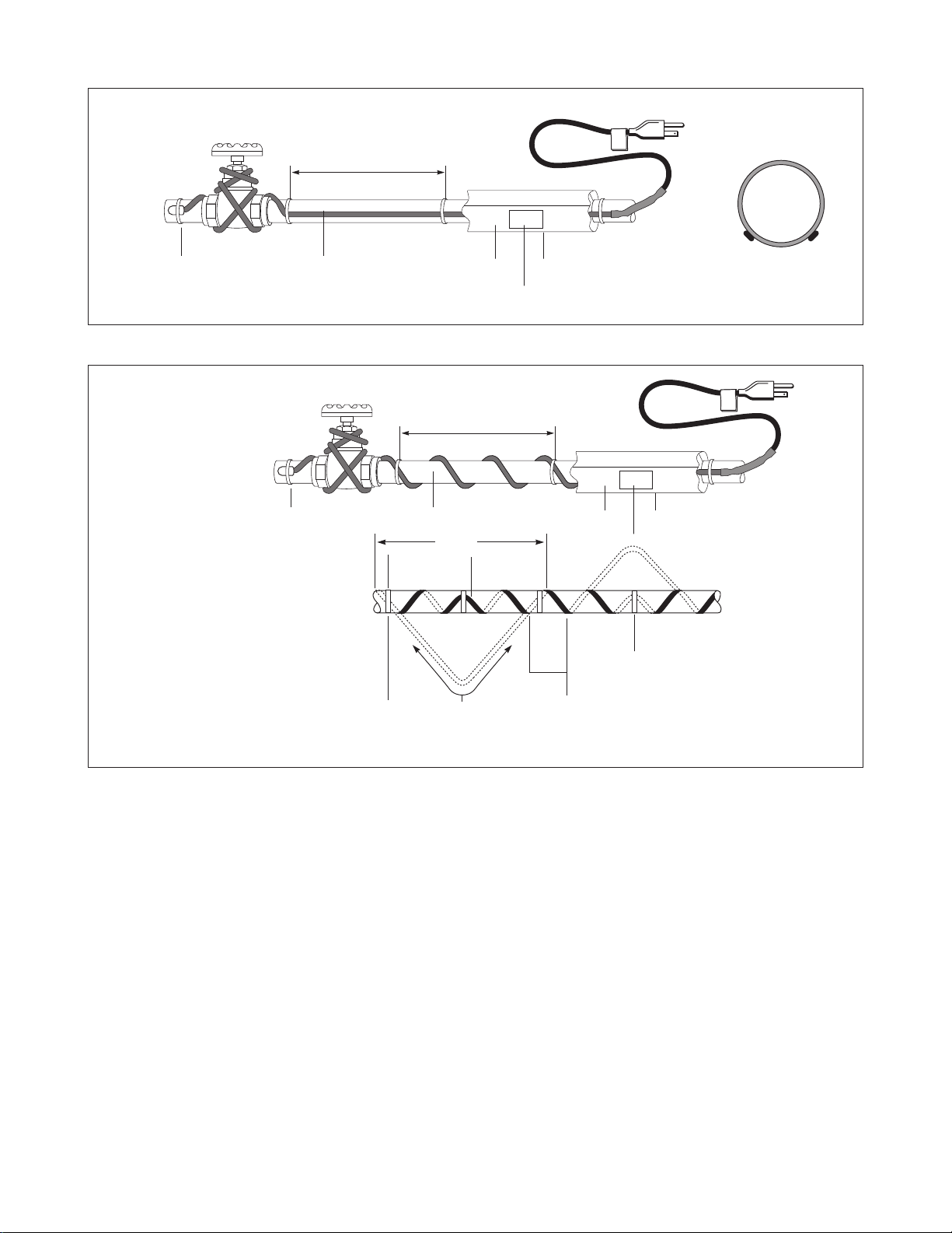
• For valleys, run the heating cable two thirds of the way up and
down the valley.
• For gutters 5-6 inches wide use 2 runs of heating cable.
• For gutters wider than 6 inches contact nVent, (800) 545-6258
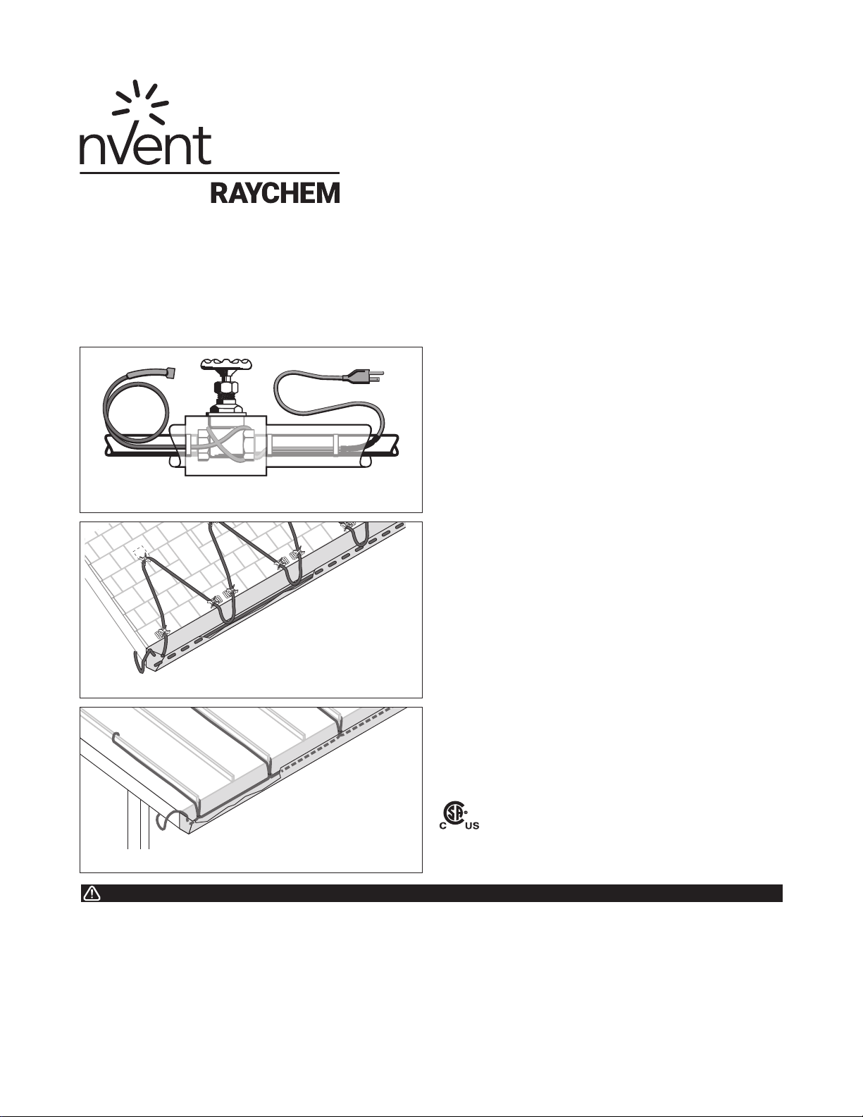
Heating cable installation
2'
UV-resistant cable tie
Figure 5. Standard roof
1. Prepare for installation.
• Store the heating cable in a clean, dry place.
• Use only the following nVent accessories to satisfy code
and agency requirements:
- nVent RAYCHEM H915 Hanger Bracket
- nVent RAYCHEM H913/H914 Roof Clips
• Make certain gutters and downspouts are free of leaves and
other debris.
• Carefully plan the routing of the heating cable for roof and
gutter de-icing.
2. Position and attach the heating cable on roofs.
• Loop the heating cable on the overhang area of the roof. This
is the part that extends past the building wall. Extend the
bottom of each heating cable loop over the roof edge and,
using a UV-resistant cable tie, connect the bottom of each
loop to the cable running in the gutter to ensure a drainage
channel off the roof and into the gutter and downspout. The
cable running in the gutter should remain against the bottom
of the gutter as shown in Figures 5 and 6.
UV-resistant
cable tie
Figure 6. Standing seam metal roof
Table 4. Tracing heights for different roof styles
Shake and Shingle Roof
Roof of
overhang (in)
Tracing width
(in)
Tracing
heights (in)
Feet of
FrostGuard per
foot roof edge
None* 2 18 2
12 2 18 2.8
24 230 3.8
36 242 4.8
Standing Seam Metal Roof**
Eave overhang
(in)
Standing Seam
Spacing (in)
Tracing heights
(in)
Feet of FrostGuard
per foot of roof edge
None* 18 18 2.5
12 18 24 2.8
24 18 36 3.6
36 18 48 4.3
None* 24 18 2.0
12 24 24 2.4
24 24 36 2.9
36 24 48 3.6
*Gutter required
** No additional heating cable is required for gutters when tracing standing
seam metal roofs