If the instructions are not followed correctly, or if
any of the insulation layers or the copper foil are
incorrectly cut, then the integrity of the upper
termination is affected.
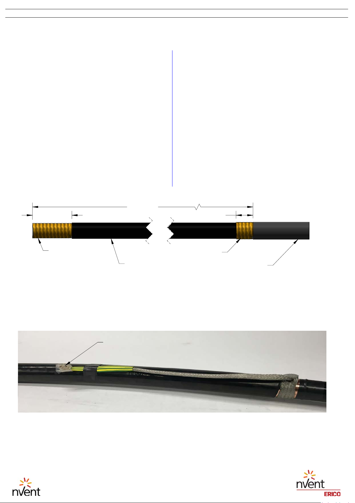
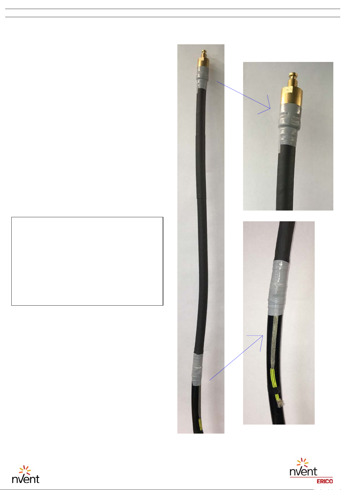
1.
The Ericore cable is marked in 1 meter
increments for its entire length. Start from the
end of the cable with lower number meter
markings. At a distance of 1200 mm (47 1/8
in.), carefully cut a shallow notch into the black
outer insulation no deeper than 1mm (3/64
in.).
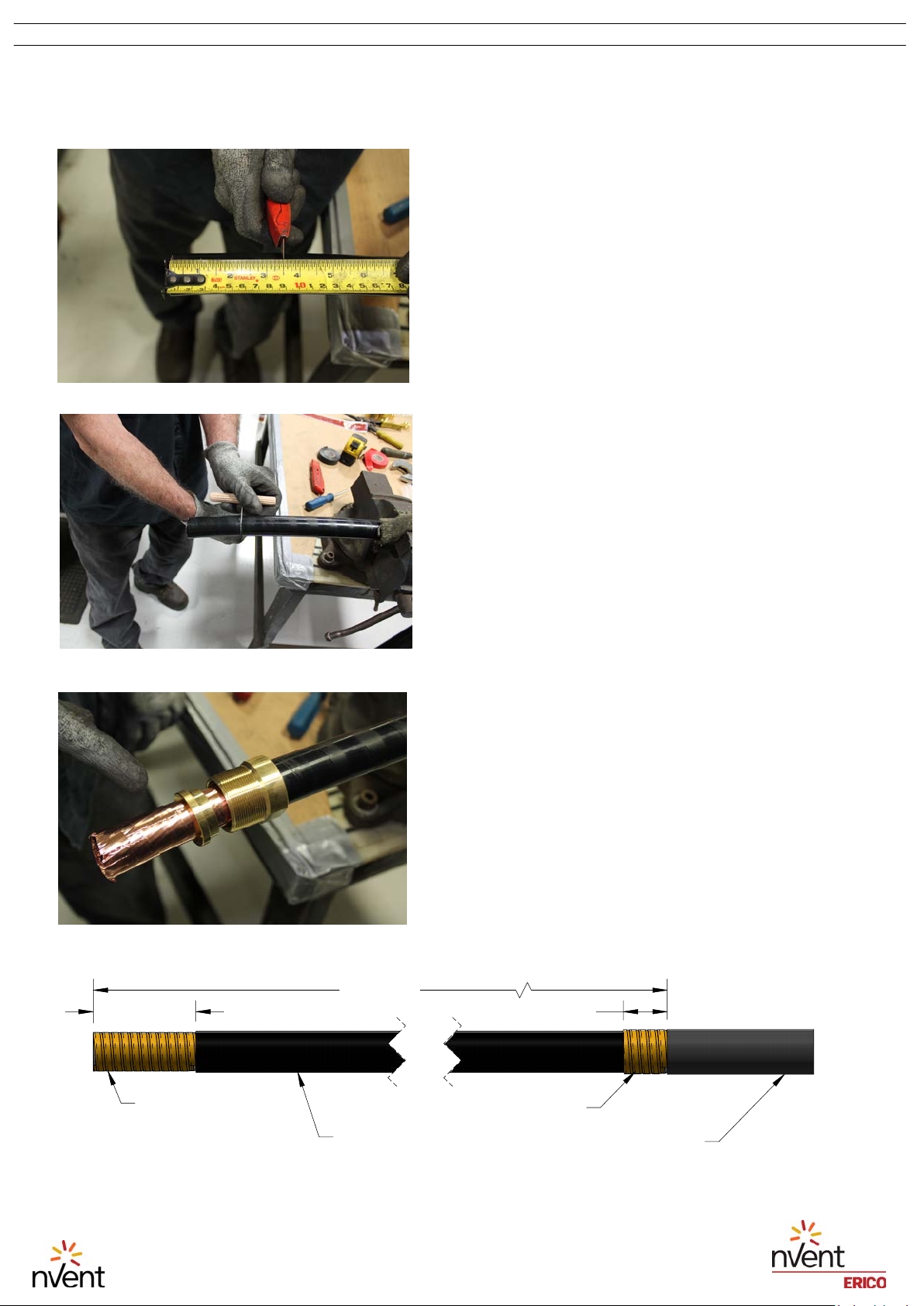
2.
Using the insulation cutting tool (15), cut
around the circumference of the black outer
insulation until the copper screen underneath
is exposed, (see Figure 2). Do NOT use a knife
instead of the provided cutting tool.
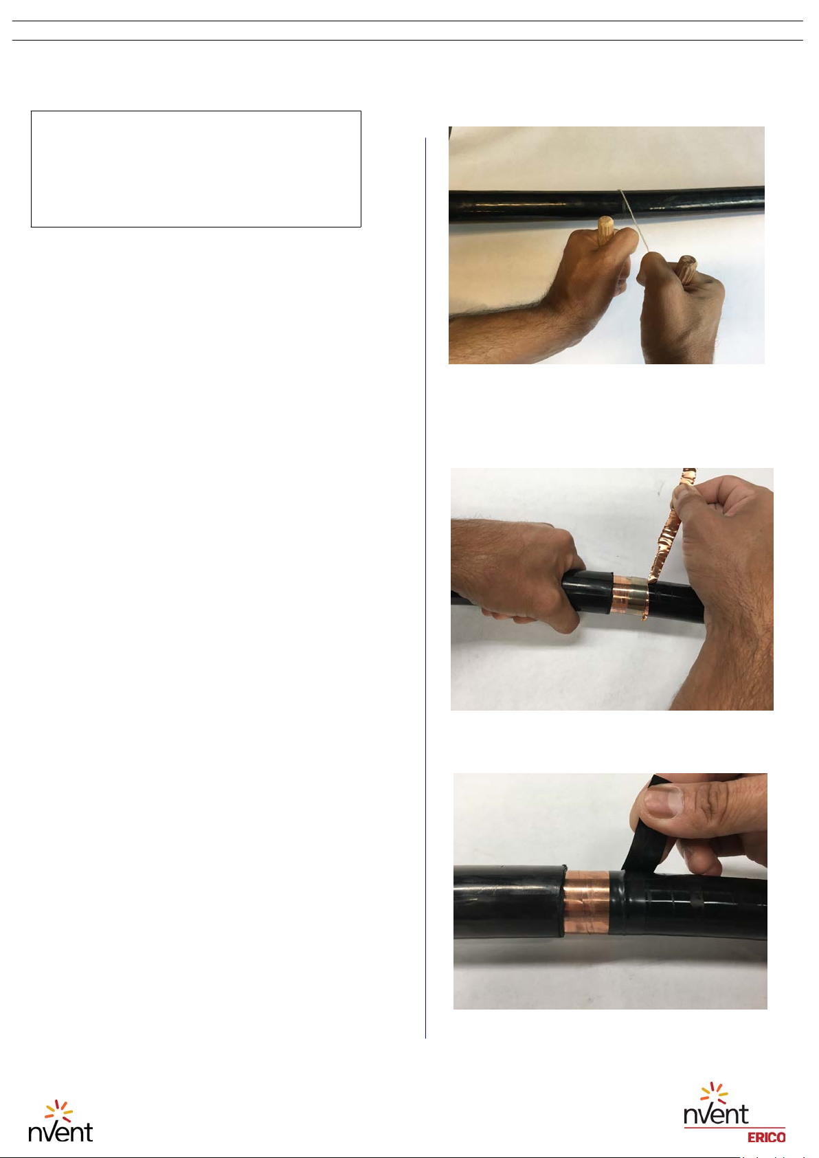
3.
Using a utility knife (1), carefully cut the
outer insulation of the cable to a depth of no
more than 1 mm (3/64 in.), for the full 1200
mm (47 1/8 in.), in the direction of the end of
the cable. Be sure not to cut so deep as to
expose or damage the copper tape underneath.
Starting from the end of the cable, carefully
remove the outer insulation and discard.
4.
Carefully clean up the friction cut, removing
any burrs for a neat finish.
5.
Using a screwdriver (5), fit the roll sping (19)
30 mm (1 1/4 in.) from the end of the outer
insulation over the exposed copper tape.
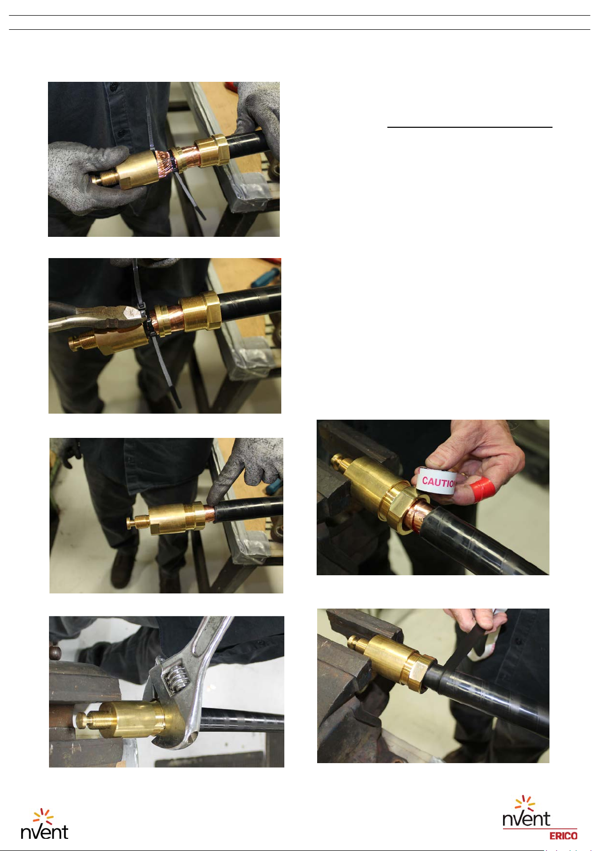
Figure 2:
Use of the insulation cutting
tool to cut the insulation without
damaging the layers beneath
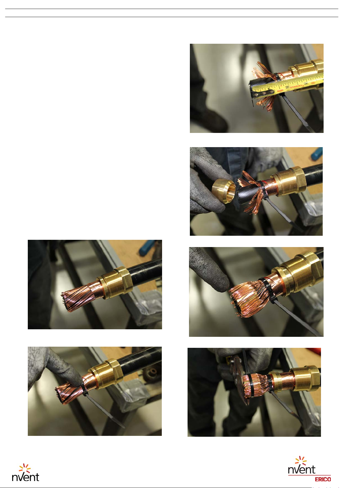
Figure 3:
Using the roll clip to cut and
remove the copper screen
Figure 4:
Placing PVC tape to prevent
further unraveling
Refer to Figure 5 on page 3 for the
following instructions (1 to 8).
The Insulation Cutting Tool uses friction
to cut into the sheath and is less likely to
damage the layers underneath than
using a knife. When the instructions call
for the knife to be used, be sure not to
cut any deeper than instructed.
IP8519_A
2 OF 11
INSTRUCTION SHEET
© 2019 nVent All Rights Reserved
TECHNICAL SUPPORT
www.nVent.com
nVent, nVent CADDY, nVent ERICO Cadweld, nVent ERICO Critec, nVent ERICO, nVent ERIFLEX, and nVent LENTON are owned by nVent or its
global affiliates. All other trademarks are the property of their respective owners. nVent reserves the right to change
specifications without prior notice.