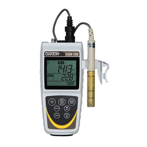
Oakton CON 10 User manual

OPERATING INSTRUCTIONS
OAKTON®35607-00
CON 10
Basic Conductivity/TDS Meter
Printed in Singapore 08/00 R2
TDS/Conductivity/°C meter
CON 10 Series
HOLD MODE
ON
OFF
CAL
MEAS ENTER
RANGE
C
MEAS
µs
COND ATC

Table of Contents
1. Introduction ............................................................................................3
2. Display and Keypad Functions............................................................ 4-5
2.1 LCD display...........................................................................................................................4
2.2 Keypad....................................................................................................................................5
3. Preparation ..........................................................................................6-9
3.1 Inserting the batteries...........................................................................................................6
3.2 Connecting the probe and temperature sensor................................................................7
3.3 Attaching the probe holder to the meter...........................................................................8
3.4 Inserting the probe into the probe holder.........................................................................8
3.5 Connecting the AC adapter.................................................................................................9
4. Calibration........................................................................................10-13
4.1 Preparing for calibration....................................................................................................10
4.2 Calibrating for Conductivity.............................................................................................11
4.3 Calibrating for TDS .......................................................................................................12-13
5. Temperature Calibration.......................................................................14
5.1 One-point temperature compensation.............................................................................14
6. Measurement....................................................................................15-16
6.1 Range Selection ...................................................................................................................15
6.2 Measurement using Automatic Temperature Compensation......................................15
6.3 Measurement using Manual Temperature Compensation...........................................16
7. HOLD......................................................................................................17
8. Probe Care and Maintenance................................................................18
9. Probe Replacement ...............................................................................19
9.1 Zero calibration ...................................................................................................................19
9.1 Two point temperature calibration...................................................................................20
10. Troubleshooting ..................................................................................21
11. Error Messages ....................................................................................22
12. Specifications ......................................................................................23
13. Accessories...........................................................................................24
14. Addendum 1: Conductivity to TDS Conversion Factors......................25
15. Addendum 2: Calculating TDS Conversion Factors ............................26
16. Warranty .............................................................................................28
17. Return of Items ...................................................................................28
3
TDS/Conductivity/°C meter
CON 10 Series
HOLD MODE
ON
OFF
CAL
MEAS ENTER
RANGE
C
MEAS
µs
COND ATC
1. Introduction
Thank you for selecting the Oakton® 35607-00 conductivity/TDS meter. Included
with your meter is an epoxy-body stainless steel probe with built-in temperature
sensor and cable, a built-in four position probe attachment and a built-in meter
stand.
Your meter includes electrode holders and batteries.
Please read this manual thoroughly before operating your meter.

4
2. Display and Keypad Functions
Display
The LCD has a primary and secondary display.
• The primary display shows the measured Conductivity or TDS reading.
• The secondary display shows the temperature of the reading in °C.
The display also shows error messages, keypad functions and program functions.
C
ppmt
ATC
READY
AUTO
COND
CAL
MEAS
µmS
Temp
HOLD
ERR ON
OFF
TDS
2.1
Primary display
Secondary display
MEASurement
mode indicator
READY
indicator
HOLD
indicator Auto-Ranging
indicator
ERRor
indicator
Low battery
indicator
Conductivity
or TDS mode
indicator
ppm or ppt
indicator
µS or mS
indicator
Temperature
calibration
mode indicator
Automatic
Temperature
Compensation
indicator
°C
indicator
MEMory
indicator

5
Keypad
The large membrane keypad makes the instrument easy to use. Each button, when
pressed, has a corresponding graphic indicator on the LCD.
ON/OFF ................Powers and shuts off the meter.
HOLD ....................Freezes the measured reading. To activate, press HOLD while in
measurement mode. To release, press HOLD again
MODE....................Selects the measurement parameter: COND (Conductivity), TDS
(total dissolved solids) or TEMP .
CAL/MEAS ..........Toggles user between Calibration and Measurement mode.
ENTER/RANGE ..Confirms your values. Switches to manual ranging and can scroll
to your selected measurement range for conductivity or TDS
▲/▼........................scrolls values up and down to the values you want
2.2
HOLD MODE
ON
OFF
CAL
MEAS ENTER
RANGE

6
3. Preparation
Inserting the Batteries
Four AAA batteries are included with your meter.
1. Use a Phillips screwdriver to remove the two screws holding the battery cover.
See Figure below.
2. Lift meter stand to expose battery cover. Remove battery cover.
3. Insert batteries. Follow the diagram inside the cover for correct polarity.
4. Replace the battery cover into its original position using the two screws
removed earlier.
3.1
Battery
compartment
Remove these
two screws to
access battery
compartment

7
Connecting the Probe and Temperature Sensor
NOTE: Keep connector dry and clean. Do not touch connector with soiled hands.
1. Slide the BNC connector of the probe over the BNC connector socket on the
meter. Make sure the slots of the connector are in line with the posts of the
socket. Rotate and push the connector clockwise until it locks
See figure
2. To remove probe, push and rotate the connector counter clockwise . While
holding onto the metal part of the connector, pull probe away from the meter.
CAUTION: Do not pull on the probe cord or the probe wires might disconnect.
Temperature Sensor
The temperature sensor uses a phono jack to connect with the socket on the meter.
Insert the jack into the socket as shown in figure
3.2
BNC connector socket
BNC connector
A
B
A
B

8
3.3 Attaching the Probe Holder to the Meter
1. Place the probe holder with the flange facing the slot on the meter.
See Figure
2. Gently slide the flange of the holder into the slot on the meter. Make sure the
holder is secured properly into the slot.
You can attach the probe holder in different positions.
See figure
This flexibility facilitates one-handed operation.
Inserting the Probe into the Probe Holder
One probe holder is included with your meter.
NOTE: Do not use excessive force when inserting probe into holder.
1. Insert the probe into the opening of the holder until the top housing of
the probe touches the top of the holder.
B
A
B
A
3.4

9
Connecting the AC Adapter
The AC adapter is not included with your meter; order separately on page 24.
1. Insert the AC jack as shown in figure below.
2. Switch off the meter before plugging the adapter into the power source.
This safety precaution protects the software in your meter.
3. Press the ON/OFF button to switch meter on.
D
D
3.5

10
4. Conductivity/TDS Calibration
Preparing for calibration
Selecting a calibration standard
For best results, select a conductivity or TDS standard near the sample value you are
measuring. Alternatively, use a calibration solution value that is approximately 2/3 the
full scale (F.S.) value of the measurement range you plan to use. For example, in the 0
to 1999 µS range, use a 1413 µS solution for calibration.
Calibrating the meter in conductivity range(s) also calibrates the corresponding TDS
range. A calibration value in the TDS mode of a particular range replaces a prior cali-
bration value in the corresponding conductivity mode if both fall in the same range,
and vice versa. The following table lists the corresponding ranges:
You only need one calibration for measurement of the entire range of the meter. If a
range is not calibrated, the meter automatically detects the closest range calibrated and
uses that calibration information. However, only the ranges that have been calibrated
have maximum accuracy.
When to calibrate
If you are measuring in solutions with conductivity lower than 100 µS, or TDS lower
than 50 ppm, calibrate the meter at least once a week to get specified ±1% F.S. accuracy.
If you are measuring in the mid ranges, calibrate the meter at least once a month. If you
make measurements at extreme temperatures, calibrate at least once a week.
4.1
Conductivity range TDS range
0.00 to 19.99 µS 0.00 to 9.99 ppm
0.0 to 199.9 µS 10.0 to 99.9 ppm
0 to 1999 µS 100 to 999 ppm
0.00 to 19.99 mS 1.00 to 9.99 ppt

11
Conductivity calibration
1. Select the conductivity standard for calibration. Select a standard with a value
closest to the expected value of measurements in the sample.
2. Pour 3 cm of the standard into two separate clean containers.
3. Turn the meter on. All the LCD segments display for a few seconds. The LCD
then switches into the conductivity measurement mode.
4. Rinse the probe in one of the containers. Gently stir the probe. Rinsing removes
contaminants that offset the calibration, and prevents error.
5. Dip the rinsed probe into the other container. Tap probe on bottom of container to
remove air bubbles. Let the probe stabilize to the solution temperature.
6. Press MODE to select conductivity mode. The COND indicator should show
at the bottom of the display.
7. Press CAL to begin calibration. The CAL
annunciator blinks showing the calibration
mode is on. Example: the display shows
712 µS for 708 µS calibrating solution.
See figure
8. Press the ▲or ▼keys to scroll to the
calibration standard value of 708 µS.
See figure
9. Press ENTER/RANGE to confirm
calibration. The CAL indicator stops
flashing and remains on the screen for
3 seconds. The meter than switches back
to measurement mode.
See figure
10. Repeat for other ranges if desired.
NOTE: At any time during the calibration,
you may exit the Calibration mode and return
to Measurement mode by pressing the CAL/
MEAS key. The meter will keep the old
calibration data and be unharmed.
Calibration error
For conductivity calibration, ERR on the
display shows whenever the calibration value
input into the meter is different from the
initial value displayed by more than 20%.
ERR displayed warns you of improper probe
use or bad calibration technique.
See figure
B
C
µS
ATC
AUTO CAL
COND
4.2
B
MEAS
C
µS
ATC
AUTO
COND
C
C
µS
ATC
ERR
AUTO MEAS
COND
D
D
C
C
µS
ATC
READY
AUTO
COND
CAL
A
A

12
TDS calibration
Option 1: TDS calibration using TDS standards
1. Select the TDS standard for calibration. Our OAKTON calibration solutions
have TDS values on the labels. For conversion factors other than those listed,
see Addenda 1 and 2, pages 25-26.
2. Pour 3 cm of the standard into two separate clean containers.
3. Turn the meter on. All the LCD segments display for a few seconds. The LCD then
switches into the conductivity measurement mode.
4. Rinse the probe in one of the containers. Gently stir the probe. Rinsing removes
contaminants that offset the calibration, and prevents error.
5. Dip the rinsed probe into the other container. Tap probe on bottom of container to
remove air bubbles. Let the probe stabilize to the solution temperature.
6. Press MODE to select TDS mode. The TDS indicator should show at the bottom
of the display.
7. Press CAL to begin calibration. CAL annun-
ciator blinks showing the calibration mode
is on. Example: display shows 747 ppm for
706 ppm (or 1413 µS) calibrating solution.
See figure
8. Press the ▲or ▼keys to scroll to the
calibration standard value of 706 ppm
See figure
9. Press ENTER/RANGE to confirm
calibration. The CAL indicator stops
flashing and remains on the screen for
3 seconds. The meter than switches back
to measurement mode.
See figure
10. Repeat for other ranges if desired.
NOTE: At any time during the calibration,
you may exit the Calibration mode and return
to Measurement mode by pressing the CAL/
MEAS key. The meter will keep the old
calibration data and be unharmed.
Confirmation error
An error message means the meter does not allow the slope adjustment to the calibra-
tion procedure given the value of Conductivity-to-TDS conversion factor. See Option 2
for another TDS calibration method for adjusting the Conductivity-to-TDS conversion
factor. Press CAL/MEAS to escape the ERR message and abort the calibration attempt.
4.3
C
ppm
ATC
AUTO CAL
TDS
B
READY
MEAS
C
ppm
ATC
AUTO
TDS
C
C
ppm
ATC
READY
AUTO
TDS
CAL
A
B
C
A

13
Option 2: TDS calibration using conversion factors
TDS values are related to conductivity. You
can calibrate the meter using conductivity
standards as described above and then
program the meter with a given conversion
factor.
1. Perform the conductivity calibration
procedure on page 11.
2. Select the correct Conductivity-to-TDS
conversion factor. Addendum 1 on page 25
lists some commonly used conversion factors. You can calculate the TDS conversion
factor for other solutions using the formula show in Addendum 2, page 26.
3. Turn the meter off if necessary; then hold down the CAL/MEAS key and press
ON/OFF. Release ON/OFF before releasing CAL/MEAS.
4. Press the ENTER key three times. The TDS factor displays.
See figure
5. Press the ▲or ▼keys to adjust the value of the primary display until it is the same
or close to the selected/calculated value.
6. Press ENTER to confirm selected value.
7. Turn the meter off, then turn meter back on.
The meter is now ready for measurement.
TDS
CAL
A
A

14
5. Temperature Calibration
The built-in temperature sensor included in the probe is factory calibrated. Over
time, the temperature sensor response may vary. If you suspect temperature errors,
calibrate your sensor using the following one-point calibration procedure.
If you purchase a replacement probe, you must complete a two-point temperature
calibration. See section 8, Probe Replacement, for details (pages 19-20).
1-point temperature calibration
1. Press the MODE key and select temper-
ature mode (TEMP). (Make sure you are
in MEAS before you begin calibration
See figure
2. Press CAL. This brings you into the
calibration mode. The primary display
shows the measured Conductivity value
and the secondary display shows the
temperature at factory calibration value.
See figure
3. Compare the displayed temperature to
that of an NIST thermometer or other
thermometer known to be accurate.
4. Press the ▲or ▼keys to adjust the
reading to agree with your temperature
standard. In the figure at right, the
desired temperature is 22.0. Use the
▲key to increase the temperature
reading to 22.0°C.
See Figure
NOTE: Temperature calibration with the
probe is restricted to ±5°C from the initial
value displayed during calibration.
Attempts to adjust reading beyond this
range will result in ERR displaying on
the LCD.
4. Press ENTER/RANGE to confirm your
selected correct temperature. The meter
reverts to the measurement mode. The
meter is now calibrated for temperature
compensation.
See Figure
A
TEMP
C
ATC
AUTO CAL
B
B
C
ATC
AUTO MEAS
TEMP
A
TEMP
CAL
C
ATC
AUTO
C
TEMP
C
ATC
AUTO MEAS
D
C
D
5.1

15
6. Measurement
Range Selection
The 35607-series meters will default to the auto-ranging mode. Auto-ranging deter-
mines and selects the range that gives you the greatest resolution and accuracy.
Alternatively, you can manually select one of four ranges using the range key. For
example, if you prefer the meter to display a reading as 0.50 mS rather than 500 µS,
while in measurement mode, select the 0 to 19.99 mS range using the range key.
NOTE: Accuracy is a percent of full-scale, so using your meter in the lowest range
that will display your measurement will result in the greatest accuracy.
Measurement with Automatic Temperature Compensation
1. Switch on the meter. The MEAS annunciator and the AUTO (Auto-ranging)
annunciator display on the top center of the LCD.
See figure
2. Rinse the probe with deionized or
distilled water before use to remove
any impurities adhering to the
electrode body.
3. Dip the probe into the sample.
Make sure there are no air bubbles
trapped in the slot of the probe. To
remove air bubbles, give the probe a
gentle shake, making sure the electrode
tip is submerged.
4. Stir the probe gently in the sample
to create a homogenous sample.
Allow a few seconds for the temperature
reading to reach solution temperature.
5. Take readings. When the reading is
stable, a READY annunciator displays.
See figure
The READY annunciator appears when the reading stabilizes within a range of ±1
unit/15 seconds. The reading holds until the measured value exceeds the specified
range and the READY annunciator turns off.
A
B
C
ATC
µS
AUTO
READY MEAS
COND
B
C
ATC
µS
AUTO MEAS
COND
A
6.1
6.2

16
Measurement with Manual Temperature Compensation
1. Leave the temperature sensor phono jack unplugged from the meter.
Attach the probe with only the BNC connector.
2. Switch on the meter. The MEAS annunciator and the AUTO (Auto-ranging)
annunciator display on the top center
of the LCD.
3. Press MODE and select temperature
mode (TEMP). Make sure you are
in MEAS.
4. Press CAL to enter the calibration
mode. The primary display shows
the measured Conductivity value and
the secondary display shows the temp-
erature previously set for manual
temperature compensation (factory
default of 25.°C).
See figure
5. Press the ▲or ▼keys to adjust your
temperature readings, in this example:
35.0°C.
See figure
6. Press ENTER to confirm settings. The meter reverts to measurement mode. You
may now take measurements following steps 2-5 in the section “Measurement
with Automatic Temperature Compensation” (page 15).
A
B
TEMP
C
AUTO CAL
ppm
B
C
AUTO MEAS
TEMP
CAL
ppm
A
6.3

17
7. HOLD function
This feature lets you freeze the value of
the Conductivity or TDS and temperature
readings for a delayed observation.
HOLD can be used any time when in
MEAS mode.
1. To hold a measurement, press the
HOLD key while in measurement
mode. "HOLD" will appear on the
display.
See Figure
2. To release the held value, press HOLD
again. Continue to take measurements.
NOTE: This meter will hold a reading
for up to 20 minutes, because it
features automatic shutoff after
20 minutes to conserve batteries.
C
ATC
µS
HOLD
COND
A
A

18
8. Probe Care and Maintenance
Keep the conductivity probe clean. Rinse the probe twice, and gently swirl it while
you take readings. For best accuracy, soak a dry probe for at least 5 to 10 minutes or
longer before calibration or taking readings. Wash the probe with deionized or tap
water before storing it. Never scratch the stainless steel portions with a hard sub-
stance. Do not strike the probe against any hard surface.
Do not make continuous contact with your solutions. Readings rise over a continu-
ous period of time if you soak your probe.
Do not immerse the probe in oily solutions. Clean the electrode thoroughly by
immersing it in an agitated mild detergent bath. Wipe the probe with a soft tissue
paper. Wash thoroughly in tap water and then in deionized water. Recalibrate the
meter after cleaning the probe.

19
9. Probe Replacement
Your meter and probe have been factory calibrated to each other for maximum
accuracy. If you notice a reduction in accuracy after replacing your probe, perform
a zero calibration and two-point temperature calibration.
Zero calibration
NOTE: the probe must be dry and in air for zero adjustment.
1. Connect the BNC and phone jacks of the probe to the conductivity meter.
2. Turn the meter off.
3. Press CAL/MEAS and then press ON/OFF, while still holding down
CAL/MEAS. Release ON/OFF before releasing CAL/MEAS.
4. Press ENTER three times, and then press
CAL/MEAS one time. The LCD shows
r1.0 on the secondary display and 0.00 µS
on the primary display. The r1.0 indicates
that you are in the first, or lowest range.
See figure
5. Press ENTER to calibrate the range
or CAL/MEAS to skip calibration
of the range.
6. At each of the measurement ranges, press
ENTER if zero adjustment is required.
Once ENTER is pressed, a value displays
on the LCD. Wait until the value is low
and as stable as it can be before pressing
ENTER again. This step adjusts zero
for the selected range.
See figure
7. Repeat step 6 for the other ranges if
necessary. If you do not want to repeat
this step, press CAL/MEAS to skip to
the next range.
COND
CAL
B
µS
CAL
COND
A
A
B
9.1

20
Two point temperature calibration
After zero calibration, the meter proceeds to program 6.0, for temperature calibration
of the probe. The temperature in °C shows in the primary display and “r6.0” shows
in the secondary display.
See figure
1. Press CAL/MEAS until the meter
automatically switches off to skip
this section of the calibration.
Do NOT press ENTER unless you
have completed the steps below.
Pressing ENTER replaces current
temperature calibration data and
causes measurement errors.
2. Prepare two constant temperature baths, one at a temperature below
5°C (low temperature bath) and the other at between 50°C to 60°C
(high temperature bath).
3. Dip the probe into the low temperature bath. Allow 5 to 10 minutes for
the probe to stabilize.
4. Press the ▲or ▼keys to fine tune temperature reading to match bath temperature.
5. Press ENTER. The screen now shows the A-to-D count corresponding to your
low temperature calibration point. This is a five digit number with the first digit
appearing in the secondary display and
the rest of the digits in the primary display.
In our example at right, the A-to-D count
is 13490.
See figure
6. Let the count stabilize, then press
ENTER again. This confirms your low
temperature calibration point, and moves
you into high temperature calibration
(“r6.1) If you do not want to confirm your calibration, press CAL/MEAS.
7. Repeat steps 4-6 with high temperature bath.
To exit from the hardware calibration at any point, press ON/OFF to switch off the
meter and abort the calibration. Only calibration points that have been confirmed
by pressing ENTER will be retained.
CAL
TEMP
A
TEMP
CAL
B
A
B
9.2
Table of contents
Other Oakton Measuring Instrument manuals

Oakton
Oakton PH550 User manual

Oakton
Oakton pHTestr 50 User manual

Oakton
Oakton 35701-00 User manual

Oakton
Oakton ECTester11 User manual

Oakton
Oakton WD-35610-00 User manual

Oakton
Oakton pHTutor User manual

Oakton
Oakton 35612-series User manual

Oakton
Oakton pH 5+ User manual

Oakton
Oakton EcoTestr pH1 User manual

Oakton
Oakton CON 6 User manual

Oakton
Oakton 35616-00 User manual

Oakton
Oakton WD-35427-10 User manual

Oakton
Oakton pH 10 Series User manual

Oakton
Oakton pH 300 User manual

Oakton
Oakton pH 610 User manual

Oakton
Oakton EC250 User manual

Oakton
Oakton CON 400 User manual

Oakton
Oakton Bench 2700 Series User manual

Oakton
Oakton ION 5 Acorn Series User manual

Oakton
Oakton 450 Series User manual