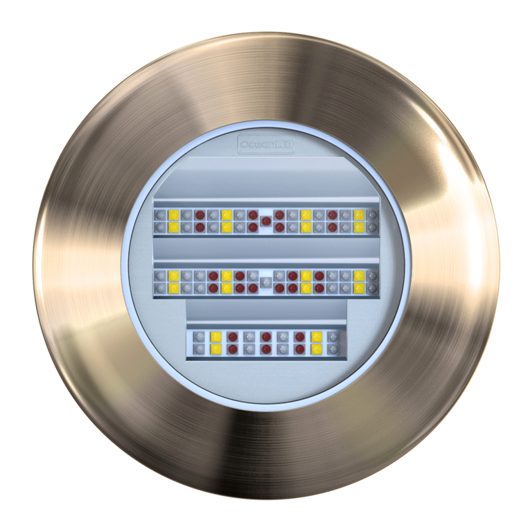
Oceanled Explore E7 Series User manual

LIGHT. YEARS AHEAD. WWW.OCEANLED.COM
OceanLED MANUAL / EXPLORE SERIES / E7 / REVISION 2
2019
INSTALLATION & OPERATION MANUAL
EXPLORE SERIES E7

EXPLORE E7
2019 INSTALL & OPERATION MANUAL
1
Preface
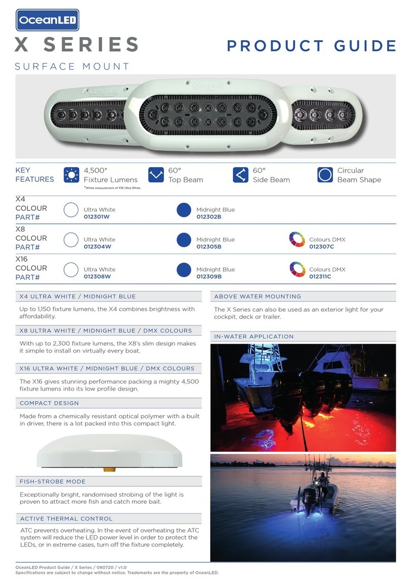
READ AND FOLLOW ALL INSTRUCTIONS IN THIS MANUAL
CAUTION
(Risk Group 2): Possibly hazardous optical radiation emitted from this product. Do not stare at operating
lamp. May be harmful to the eye.
WARNINGS
Before installing your OceanLED Light, read and follow all warning notices and instructions which are
included. Failure to follow safety warnings and instructions can result in property damage, severe injury or
even death.
Before installing your OceanLED Light, check local laws for restrictions regarding the use of coloured lights
in your area.
Do not operate lights out of water for a period longer than 5 minutes followed by an OFF period of at least 1
hour. Exceeding this may cause damage to the light unit.
Ensure the bonding point of the light is fitted to the cathodic protection system on the vessel. Check
conductivity between earth bonding point and aluminium bronze front bezel. If mounting the light to metal,
carbon fibre or wooden hull, ensure that suitable measures have been put in place to account for the effects
of galvanic corrosion or wood deterioration, i.e. use of Delrin sleeve components (Isolation Kit).
Salt is an inherently corrosive material. Metal parts and certain natural and man- made surfaces are
particularly susceptible to corrosion and deterioration when used in and around saltwater. Some OceanLED
lights contain combinations of plastic and polymer products which are impervious to saltwater corrosion,
however, screws and fasteners used for the installation must be of a marine grade type stainless steel or
equivalent and monitored annually to ensure the lights remain in service for years to come.
Never connect/disconnect lights with power applied as irreversible damage may occur.
Ensure lights are always fully submerged and not fitted on planing / running surfaces that may impact on
water since this may damage the product.
Never Use Solvents! Cleaners, fuel, and other products that may contain strong solvents, such as acetone,
attack many plastics greatly reducing their strength and irreversibly damaging the special lens coatings and
cable sheathings.
Remove the protectors from the connectors on the rear of the light ONLY if the connector will be used
immediately. If the connectors on the light(s) are not in use, leave protector(s) on.
DANGER
RISK OF ELECTRIC SHOCK OR ELECTROCUTION
This underwater light must be installed by a licensed or certified electrician in accordance with all applicable
local codes and ordinances. Improper installation will create an electrical hazard which could result in death
or serious injury to swimmers, installers, or others due to electrical shock, and may also cause damage to
property. Always disconnect the power to the light at the circuit breaker before servicing the light.
EXPLORE E7
2019 INSTALL & OPERATION MANUAL
2
Contents
1 Overview.............................................................................................................................................................................4
2 Preparing the Hull ..............................................................................................................................................................5
3 Installation...........................................................................................................................................................................6
4 Operation / Maintenance .................................................................................................................................................18
5 Troubleshooting ...............................................................................................................................................................22
6 Appendix...........................................................................................................................................................................25
7 Warranty...........................................................................................................................................................................32
PRETEST
Always test the lights prior to installation. Failure to do this may result in additional installation time and could invalidate
the warranty.
IMPORTANT NOTICE
Attention Installer: This manual contains important information about the installation, operation and safe use of this
product. This information should be given to the owner and/ or operator of this equipment.
WARRANTY COVERAGE
2-year warranty from time of purchase, regardless of installation date. Please refer to www.oceanled.com/downloads
for full warranty statement.

EXPLORE E7
2019 INSTALL & OPERATION MANUAL
3
Installation checklist:
1. Decide on light spacing – OceanLED recommendations available.
Rear of lights must never be exposed to wet environments inside the hull.
2. Decide on light angles – OceanLED Personalised Service available on request.
3. Ensure the correct power kit is selected and installed (AC or DC power kit).
4. Ensure correct cable gauge is used (refer to relevant cable gauge chart).
5. Control system chosen (switch control, OceanLED DMX control kit, 3rd party DMX control)
Max 32 lights per DMX chain.
6. Correct length light fixture chosen (Extension kit required for hulls thicker than 55mm).
7. Preparing the hull (Isolation kit required for conductive hull materials or wooden hulls).
8. Make sure the lights have been fitted following the correct reflector orientation.
9. Correct marine sealant applied evenly around bezel.
Ensure fully watertight seal is created after sealant cures.
10. Correct clamping of light fixture onto hull. Never leave vessel unchecked for a few days after install.
Always check routinely for a few days after installation to ensure the install is correct and fully
sealed.
11. Light(s) correctly bonded and vessel bonding system check carried out (refer to relevant schematic
and test procedures).
12. Test installation BEFORE entering water. Never connect/ disconnect lights whilst powered ON.
Never leave lights ON out of water for longer than 5 minutes followed by an off period of 1 hour.
13. Trouble shooting if required - most issues can be resolved by following the guidelines.

EXPLORE E7
2019 INSTALL & OPERATION MANUAL
4
1 Overview
Product components breakdown
Power Source
Most installations will utilize on-board 12/24V DC power supply from a marine battery. However, if AC power is being
used on the vessel, an Explore AC power kit must be purchased. Please check the Explore E7 Light Choice Diagram
in section 6.3 to evaluate all the options currently offered by OceanLED.
Use the chart below to determine the appropriate power supply.
Power Consumption and Recommended Fuse values
Model
Current @
12V DC
Current @
24V DC
Max Nominal
Power
consumption
Minimum PSU
(15%
reserve
)
Recommended
fuse
12V/24V DC
E7 Dual White/Blue
7.8 A
4.7 A
113W
130W
10 A
E7f Colour DMX
6.8 A
3.2 A
83W
94W
10 A
Identifying your model
Explore E7
Dual Blue/White
Explore E7
Colours DMX
A- Light Unit B- Connector
protection caps
C- Compression
washer
D- Clamping
clips + bolts
E- Locking
ring

EXPLORE E7
2019 INSTALL & OPERATION MANUAL
5
2 Preparing the Hull
When installing an Explore unit, please ensure there is enough space on the inside of the vessel to remove
the insert for maintenance/after sales services. For example, the XFM unit requires an additional 100mm / 4”
from the rear of the mounting tube to allow the insert to be removed. (See overall dimensions below).
Ensure that the part of the light inside the vessel has a diameter of 100mm / 4” around it free from any
insulation material.
OceanLED recommends using a qualified installer / technician when making modifications to your vessel.
Please also consult the manufacturer for more detail on modifications and installation.
If lights are assembled in a conductive or wooden hull, an Isolation Kit must be used. Contact OceanLED for
additional details.
Depth/Spacing
Ideally mount your lights at similar depth levels to ensure matching colour consistency through the water. Deeper lights
will look duller and possibly differ in colour compared to shallower mounted units.
Spacing / Install Depth E7
Recommended Spacing 2.5-3M (8-10’)
Recommended Installation depth (From the light waterline) 15-25CM (6-10”)
Hole Cut Out
Hole Cut out size - 83mm (3.25”) / With Isolation Kit 89mm (3.5”)
Overall Dimensions
See overall dimension schematic - section 6 appendix

EXPLORE E7
2019 INSTALL & OPERATION MANUAL
6
3 Installation
3.1 Installing the Light Fixture (Hull thickness up to 55mm)
Additional Tools needed that are not supplied by OceanLED
Marine sealant - 3M 4200 or equivalent
Cable ties
Waterproof Cable Connectors / Junction Box (optional)
Allen key (5mm)
Thread lock - Loctite 243 or equivalent.
DO NOT remove the light cartridge from the mounting tube during installation. The light cartridge MUST stay
fitted inside the mounting tube throughout the installation process to avoid the introduction of potential
contaminants that may damage the product. The light cartridge can only be removed for maintenance or after
sales purposes and OceanLED must be contacted prior to any light cartridge being removed from the
mounting tube.
OceanLED recommends dry fitting all products. When installing, be sure that the light fits the area and
secures to the hull using the appropriate hardware before applying any sealant.
When applying sealant to the light fixture, use OceanLED packaging material such as the light cardboard box
when placing the light on the ground face down to prevent lens damage.
Explore E7
Kit Includes
Explore E7 Light Clamping Kit Removal Tool

EXPLORE E7
2019 INSTALL & OPERATION MANUAL
7
Installation (Once hull preparation is complete)
1. Testlight(s) before fitting.
2. (If using Isolation Kit) Insert the Isolation Kit front washer into the drilled hole and apply marine sealant to seal
between the Front Washer and thehull.
3. Apply sealant to the rear of the mounting tube assembly’s bezel to ensure a complete unbroken seal around
the light.
Make sure sealant fills in the recess groove on the reverse of the light bezel:
4. Ensure the light angle is correct for the location before assembling the light. If available, follow OceanLED
Light Placement Chart position to indicate what light angle should be installed into each location around
the hull. The LED Indicator is used as a reference point for beam direction and should be at the top of the
rear face of the light body, as pictured, if installed correctly. If viewed from inside. From outside, the
OceanLED logo should be in the correct orientation, as below, indicating the direction of the beam. For
more details, consult Appendix 6.6.
5. Insert the complete light unit (mounting tube assembly + light cartridge) into the hull, pressing the light hard into
the hull and twist slightly to spread the sealant behind the light to ensure goodadhesion.
This process is made much easier if a second person is inside the hull to receive the light and install the
locking equipment whilst supporting the light from the outside. Breakages due to lights falling out of the hull
are NOT covered under warranty and can cause serious bodily injury as can any falling object.

EXPLORE E7
2019 INSTALL & OPERATION MANUAL
8
6. (If using IsolationKit) Insert theIsolation Kitflatwasher over themounting tube and locate it flush with the hull.
7. Insert the stainless-steel compression washer over the mountingtube.
The stainless-steel compression washer does not need to be flat to the hull, a slightly uneven surface can be
compensated by the washer.
8. Place the two C clips together to form a circle, ensuring you pair 1 threaded and 1 non-threaded hole together.
Fix the clips together using one of the screws provided sothat the clips are located approximatelyhalfway down
the length of the screw.Locate the clips into the appropriate grooves (depending on hull thickness) on outside
of the mounting tube so that the end of the screw is close to the washer. Fit the screws provided into the
remainingholes, fixing the two clips together. Leave the longer screw out to connect the light to the vessel’s
cathodic protection system. Once connected, screw down this screw to the same position as the others (see
step 10)
9. Tighten the locking screws using a 5mm Allen key,applying thread lock at point of thread contact with
locking ring. DO NOT over-tighten locking screws, as you could damage the mounting tube, and this will not
be covered under warranty.
Once you are satisfied that the unit is fully tightened, you will notice that sealant has squeezed out from
around the perimeter of the light. Using a thinner or cleaner, apply to cloth and wipe off excess sealant to
leave a clean seal. AVOID CONTACT WITH LENS. If you do not see sealant squeeze out from the body,
you have not used enough sealant or tightened the unit enough to the hull. Carefully examine the
installation to make sure the seal you have installed on the unit is fully watertight. Ifin doubt, remove light,
re-apply sealant and re-install.
10. Connect the bonding cable to the remaining screw and lock in place with the nutand shake proof washer
provided. Tighten the locking screw using a 5mm Allen key,applying thread lock at point of thread contact
with locking ring.
BONDING: The light MUST be attached to the vessels bonding / cathodic protection system. Once fitted it
is mandatory to check that there is full continuity between the vessels cathodic protection system and the
outer bezel of the mounting tube assembly (see bonding schematic – section 6 Appendix).

EXPLORE E7
2019 INSTALL & OPERATION MANUAL
9
3.2 INSTALLING THE LIGHT FIXTURE (Hull Thickness above 55mm)
Assemble the mounting tube extension kit on the back of the standard light mounting tube then follow the procedure
above in section 3.1.
1. Remove the locking ring from the mountingtube.
2. Apply thread lock (Loctite 243 or equivalent) on the thread of the additional mounting tube then screw it all the
way down onto the back of the mounting tube.
Extension kit
Kit Includes
Mounting Tube Compression Tube

EXPLORE E7
2019 INSTALL & OPERATION MANUAL
10
3. Fit the compression tube inside the mounting tube extension and slide it all the way down into the tube until it
reaches the light cartridge.
4. Screw the locking ring back onto the mounting tube extension until tight. Now follow the steps in section 3.1.

EXPLORE E7
2019 INSTALL & OPERATION MANUAL
11
3.3 INSTALLATION OF AC POWER KIT
Additional Tools needed that are not supplied by OceanLED
Screws to secure the AC Power Pack
Junction box / waterproofconnectors
Sufficient cable to connect to AC PowerPack
Suitable fuse /breaker(s)
Always consult a qualified electrician when connecting OceanLED light fixtures.
Never use power tools to secure the Power Pack: hand tighten only.
When connecting light units, please note that all OceanLED lights will operate within a specific voltage range.
Please check the electrical information to ensure cable gauge, fuse and breakers size follow the
recommendations.
Always mount Power Pack in a dry location. Drivers should not sit in standing water at any time.
The 3-core input is for power (Brown=Live; Blue=Neutral; Green/Yellow=Earth) and the two pin Deutsch
Connector is for the light.
1. Depending on the model and number of lights installed, you will need to pull the correct sized power cable from
the AC Power (breaker/fuse panel) to the Power Pack locations. Ensure the correct sized tinned marine grade
cable is used to avoidvoltage drop issues.
2. Fix Power Pack into required position. Ensure chosenPower Pack location is nearenough to connect light cable
without applying undue stress.
Never leave the bare cables unprotected. Take care to not leave the bare wire ends in bilge water before
making the waterproof connections. Water deposits in the connectors and cables will cause corrosion. Over
time water can also work its way into the unit along the inside of the cable due to capillary action causing the
light to fail. This will NOT be covered under warranty.
3. Connect the Power Pack to the AC Power.Ensure the size fuse/breaker, cable and connector have the correct
specificationandare watertight.Makesureanyheatshrinkusedcompletelyencapsulatestheouterwiresheath
(the use of glue-lined heat shrink is highly recommended to ensure water tightness). Leave the connection
unplugged to eliminate the danger ofelectrocution.
Corrosion of wire and/or water ingress into the light unit via cable is NOT covered under warranty.
4. Connect the Deutsch connector from the Power Pack to the light using the PowerCable.
5. Secure cables ensuring where the cable exits the light it is not under undue stress.Finish and test the light units
BEFORE the vessel goes into the water.
Explore AC Power kit
Kit Includes
AC Power Pack AC Power Cable (1.5m long)

EXPLORE E7
2019 INSTALL & OPERATION MANUAL
12
3.4 INSTALLATION OF DC POWERKIT
Additional Tools needed that are not supplied by OceanLED
Junction box / waterproofconnectors
Sufficient cable to connect to DC PowerPack
Always consult a qualified electrician when connecting OceanLED light fixtures.
When connecting light units, please note that all OceanLED lights will operate within a specific voltage range.
Please check the electrical information to ensure cable gauge follow the recommendations.
Never leave the bare cables unprotected. Take care to not leave the bare wire ends in bilge water before
making the waterproof connections.
in the connectors and cables will cause corrosion. Over time water can also work its way into the unit along
the inside of the cable due to capillary action causing the light to fail. This will NOT be covered under warranty.
For complete instructions on DC connections, please refer to ABYC codes of practice and other applicable
codes and ordinates for DC connections.
1. Depending on the model and number of lights installed, you will need to pull the correct sized power cable from
the DC power source (breaker/fuse panel) to the light locations to supply constant power to the light units. It is
imperative that the correct sized tinned marine grade cable is used to avoid voltage drop issues.
See section 6: Appendix for recommended cable gauges.
2. Using waterproof butt splices or IP66 waterproof junction boxes, make the connections at either end of the
system to attach the lights to the DC system. Make sure any heat shrink used completely encapsulates the
outer wire sheath (the use of glue-lined heat shrink is highly recommended to ensure water tightness).
Never install a new light fixture then leave the vessel in the water unchecked for several days.
3. It is imperative that either the OceanLED supplied fuse on each power line to eachlight or a suitable protection
device is used to protect the cable/light unit. Failure to do so will void the warranty. See table in section 1:
Overview.
4. Secure cables ensuring where the cable exits the light it is not under undue stress. Finish and test the light units
BEFORE the vessel goes into the water.
Explore DC Power kit
Kit Includes
DC Power Cable (1.5m long) Fuse kit

EXPLORE E7
2019 INSTALL & OPERATION MANUAL
13
3.5 CONTROL SYSTEM INSTALLATION
3.5.1 Switch Control
Additional Tools needed that are not supplied by OceanLED
Push switch (Normally Open).
To use Switch Control, the Control Input Cable and Terminator Kit is needed.
To connect the lights to enable control of all lights using a single switch, Explore E6 & E7 Control Link Cables
must be used. The quantity of Control Link Cables per installation is equal to the number of lights minus 1
(Example: If 10 lights are used, 9 control link cables are needed). Please consult the Explore E7 Light Choice
Diagram in section 6.3 for details.
Ensure power is disconnected before attempting to connect or solder any wire.
1. Connect/solder one end of the switch to the red wire (Switch) of the ControlCable and the other end to the
black (Ground), yellow (DMX +) and brown (DMX -).
2. Plug the Switch cable to the Control In Connector of first light.
3. Using the Control Link Cable, connect the Control Out of the first light to Control In of thenext light. Repeat until
all the lights are connected. Check the diagram below for clarification.
4. Plug the Terminator to the Control Out of the lastlight.
Control Link Cable
Control Lin
k
Cable
Switch
12/24V DC Power
12/24V DC Power
12/24V DC Power
Terminator

EXPLORE E7
2019 INSTALL & OPERATION MANUAL
14
3.5.2 OceanLED DMX ControlKits
To use OceanLED DMX Control, one of our DMX kits must be purchased from OceanLED. Please consult the
Explore E7 Light Choice Diagram for details.
To enable the DMX Control of all lights, Explore E6 & E7 Control Link Cables must be used. The quantity of
Control Link Cables per installation is equal to the number of lights minus 1 (Example: If 10 lights are used,
9 control link cables are needed).
Ensure power is disconnected before attempting to connect or solder any wire.
Please consult the manual for the purchased DMX Control Kit for more information on installation and operation.
3.5.3 3
rd
Party DMXControl
Additional Tools needed that are not supplied by OceanLED
External DMX Control System
To use a 3rd Party DMX Control, the Control Cable and Terminator Kit is needed.
To enable the DMX Control of all lights, Explore E6 & E7 Control Link Cables must be used.
The quantity of Control Link Cables per installation is equal to the number of lights
minus 1 (Example: If 10 lights are installed, 9 control link cables are required).
Ensure power is disconnected before attempting to connect or solder any wire.
1. Connect the DMX Control unit to the Control Cable following the wiring connections below:
Cable colour Signal
Shield Shield
Black GND
Yellow DMX +
Brown DMX -
Red Not used
2. Plug the Control Cable to the Control In Connector of firstlight.
3. Using the Control Link Cable, connect the Control Out of the first light to Control In of the next light. Repeat until
all the lights are connected. Check the diagram below for clarification.
The DMX standard recommends a maximum of 32 devices to be connected in one chain. If installation
requires more lights than this, please contact OceanLED for advice.

EXPLORE E7
2019 INSTALL & OPERATION MANUAL
15
Example DC Installation with OceanDMX Controller kit
Control Link Cable
Control Link Cable
Control Link Cable
Control Input Cable
Terminator Kit
Power In
Power In
Power In
Power In
WIFI Communication

EXPLORE E7
2019 INSTALL & OPERATION MANUAL
16
Example AC Installation with WIFI DMX Controller kit
4. Plug the Terminator to the Control Out of the lastlight.
Control Link Cable
Control Link Cable
Control Link Cable
Control Input Cable
Terminator Kit
Ethernet Cable Router
(For WIFI DMX)

EXPLORE E7
2019 INSTALL & OPERATION MANUAL
17
3.6 TEST YOURINSTALLATION
Always test the lights BEFORE the vessel goes back into the water. At this final stage make sure all of the system is
operational. If you have any issues, please contact your local OceanLED representative.
Never install a new light fixture then leave the vessel in the water unchecked for several days.
When the vessel is placed in the water, immediately check for leaks. Note that very small leaks may not be readily
observed. It is best not to leave the vessel in the waterfor more than 3 hours before checking it again. If there is a small
leak, there may be considerable bilge water accumulation after 24hours. If a leak is observed, youmust TAKE ACTION
IMMEDIATELY to prevent damage.

EXPLORE E7
2019 INSTALL & OPERATION MANUAL
18
4 Operation / Maintenance
4.1 OPERATION
Never connect / disconnect lights with power applied as irreversible damage may occur.
4.1.1 Switch Control
The Switch Control mode allows the user to switch between colours and strobe modes using a push switch.
The sequence for the Explore E7 Dual White/Blue is a closed loop as follows:
Solid White
Solid Blue
Fade White / Blue
Strobe Blue
Strobe White
Strobe White / Blue
50% White and 50% Blue
The sequence for the Explore E7 Colours DMX is a closed loop as follows:
Solid Chosen Colour
Strobe Chosen Colour
Colour Cycle
4.1.2 DMX Control
Please refer to the purchased DMX Controller for details about how to use it.
4.2 LIGHT CARTRIDGE REMOVAL – Single Mounting Tube
Before proceeding with this operation, you MUST seek permission from either the manufacturer or your
OceanLED representative.
DO NOT remove the light cartridge from the mounting tube during installation. The light cartridge MUST stay
fitted inside the mounting tube throughout the installation process to avoid the introduction of potential
contaminants that may damage the product.
Additional Tools needed that are not supplied by OceanLED
Allen key (2mm).
1. Turn power off and unplug all the connectors on the back of light.
2. Remove the locking ring from the mountingtube.
3. Undo one of the six screws from the back of the lightcartridge to allow theremoval tool to be placed (see image
below).

EXPLORE E7
2019 INSTALL & OPERATION MANUAL
19
To ease the removal process, another screw can be removed to act as a breather.
4. Place the removal tool under the head of the undone screw making sure that the screw engages with the slot
on the removal tool, then fasten the screw in a clockwise motion. By tightening down the screw the light
cartridge will be pulled out of the mounting tube.
5. Finish pulling the light cartridge out by hand with the help of the tool to fully remove it from the mounting tube.
4.3 LIGHT CARTRIDGEREMOVAL – Extended Mounting Tube
Before proceeding with this operation, you MUST seek permission from either the manufacturer or your
OceanLED representative.
DO NOT remove the light cartridge from the mounting tube during installation. The light cartridge MUST stay
fitted inside the mounting tube throughout the installation process to avoid the introduction of potential
contaminants that may damage the product.
Additional Tools needed that are not supplied by OceanLED
T-Handle Allen key (2mm) 80mm length.
1. Turn power off and unplug all the connectors on the back of light.
2. Remove the locking ring and the compression tube from the mounting tube.
Other manuals for Explore E7 Series
1
This manual suits for next models
2
Table of contents
Other Oceanled Underwater Lighting manuals

Oceanled
Oceanled XD16 User manual

Oceanled
Oceanled Sport Series User manual

Oceanled
Oceanled Marine LTD Sport Series User manual

Oceanled
Oceanled DISCOVER D3 User manual

Oceanled
Oceanled T Series User manual

Oceanled
Oceanled X Series User manual

Oceanled
Oceanled EXPLORE E2 User manual

Oceanled
Oceanled ALLURE XFM Series User manual

Oceanled
Oceanled X4 User manual

Oceanled
Oceanled Sport S3116d User manual