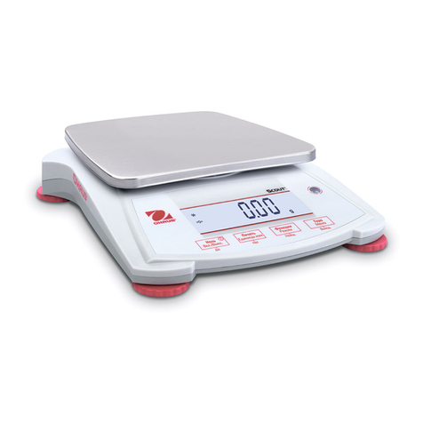
OHAUS Catapult 1000 User manual


SERVICE MANUAL
Catapult™1000 Scales
The information contained in this manual is believed to be accurate at the time of publication, but Ohaus
Corporation assumes no liability arising from the use or misuse of this material. Reproduction of this
material is strictly prohibited.
Material in this manual is subject to change.
© Copyright 2008 Ohaus Corporation, all rights reserved.
TM Registered trademark of Ohaus Corporation.


TABLE OF CONTENTS
Page No.
CHAPTER 1 GETTING STARTED
1.1 Introduction................................................................................................................1-1
1.2 Service Facilities........................................................................................................1-1
1.3 Tools and Test Equipment Required.........................................................................1-2
1.4 Specifications.............................................................................................................1-2
1.5 Operation...................................................................................................................1-3
1.5.1 Power Supply.....................................................................................................1-3
1.5.2 Overview of the Controls....................................................................................1-3
1.5.3 Basic Functions..................................................................................................1-4
1.5.4 Dynamic Weighing .............................................................................................1-4
1.6 Calibration..................................................................................................................1-5
CHAPTER 2 TROUBLESHOOTING
2.1 Introduction................................................................................................................2-1
2.2 Visual Inspection........................................................................................................2-1
2.3 Diagnostic Guide .......................................................................................................2-2
2.3.1 Diagnosis............................................................................................................2-2
2.4 Checking the Load Cell’s Signal................................................................................2-4
2.4.1 Output Voltage Test ...........................................................................................2-4
2.4.2 Resistance Test..................................................................................................2-5
2.5 Testing the Printed Circuit Board (PCB)....................................................................2-6
2.5.1 PCB Voltage Measurements..............................................................................2-6
2.5.2 Simulator Testing ...............................................................................................2-6
2.5.3 General Load Test..............................................................................................2-6
2.5.4 Calibration Test ..................................................................................................2-7
CHAPTER 3 MAINTENANCE PROCEDURES
3.1 Preventive Maintenance............................................................................................3-1
3.1.1 Preventive Maintenance Checklist .....................................................................3-1
3.2 Replacement of Major Components..........................................................................3-1
3.2.1 Replacing Load Cells .........................................................................................3-2
3.2.2 Printed Circuit Board (PCB) Replacement .........................................................3-3
3.2.3 Battery Replacement..........................................................................................3-4
3.2.4 Function Label Replacement..............................................................................3-4
CHAPTER 4 TESTING
4.1. Testing.......................................................................................................................4-1
4.2 Power Test.................................................................................................................4-1
4.3 Performance Tests Using a Scale Base....................................................................4-1
4.4 Calibration Retention Test.........................................................................................4-1
4.5 Repeatability Test......................................................................................................4-2
4.6 Off-Center Load Test.................................................................................................4-4
4.7 Off-Center Load Adjustment......................................................................................4-5
4.8 Linearity Test.............................................................................................................4-6
CHAPTER 5 PARTS LISTS & DIAGRAMS
5-1 Catapult 1000 Scale: Parts........................................................................................5-2
TABLE OF CONTENTS
LIST OF TABLES
TABLE NO. TITLE Page No.
1-1 Specifications........................................................................................................1-2
2-1 Diagnostic Guide Table.........................................................................................2-3
2-2 Color Code For Load Cell Wiring ..........................................................................2-4
2-3 Load Cell Output Readings (in mV with 3V Excitation).........................................2-5
2-4 Load Cell Resistance Readings (in Ohms) ...........................................................2-5
4-1 Repeatability Worksheet .......................................................................................4-4
4-2 Linearity Test Masses ...........................................................................................4-6
5-1 Catapult 1000 Scale: Parts ...................................................................................5-3
LIST OF ILLUSTRATIONS
FIGURE NO. TITLE
1-1 Catapult 1000 Display...........................................................................................1-3
2-1 Visual Checking Procedures.................................................................................2-1
2-2 Catapult 1000 PCB connections ...........................................................................2-4
3-1 Scale Bottom.........................................................................................................3-2
3-2 Load Cell Junction Board......................................................................................3-2
3-3 Installing a Load Cell.............................................................................................3-2
3-4 Removing screws that secure the PCB’s Bottom Plate.........................................3-3
3-5 Power Cable and Load Cell leads, soldered to the Printed Circuit Board.............3-3
3-6 Open Battery Compartment door by pressing the two inset latch levers ..............3-4
4-1 Scale drawing of Catapult 1000 Load Cell and Weighing Pan..............................4-6
5-1 Catapult 1000 Scale: Parts ...................................................................................5-2
CHAPTER 1 GETTING STARTED
1.1 INTRODUCTION
This service manual contains the information needed to perform routine maintenance and
service on the Ohaus Catapult™ 1000 Scales. The contents of this manual are contained in
five chapters:
Chapter 1 Getting Started – Contains information regarding service facilities, tools and test
equipment, measuring masses, specifications, and the mechanical and electronic functions of
the scale.
Chapter 2 Troubleshooting – Contains a diagnosis/diagnostics chart and error code table.
Chapter 3 Maintenance Procedures – Contains preventive maintenance procedures and
disassembly, repair and replacement procedures.
Chapter 4 Testing – Contains an operational test, segment display test, performance tests and
adjustments.
Chapter 5 Drawings and Parts Lists – Contains exploded views of Catapult™ 1000 Scales,
identifying all serviceable components.
Before servicing the scale, you should be familiar with the Instruction Manual which is packed
with every scale.
1.2 SERVICE FACILITIES
To service a scale, the service area should meet the following requirements:
•Must be protected from electrostatic discharge.
•Should be temperature controlled and meet the scale specifications for temperature
environmental requirements. See specifications for temperature range.
•Must be free of vibrations such as fork lift trucks close by, large motors, etc.
•Area must be clean and air must not contain excessive dust particles.
•Work surface must be stable and level.
•Work surface must not be exposed to direct sunlight or radiating heat sources.

CHAPTER 1 GETTING STARTED
1.3 TOOLS AND TEST EQUIPMENT REQUIRED
The service shop should contain the following equipment:
1. Standard hand tools.
2. Digital Voltmeter (DVM).
3. Load Cell Simulator optional.
1.4 SPECIFICATIONS
TABLE 1-1. SPECIFICATIONS
Specification C11P9 C11P20 C11P75
Capacity x readability, d 9 kg x 0.05
20 lb x 0.01 20 kg x 0.01
44 lb x 0.02 75 kg x 0.05
165 lb x 0.1
Calibration Weights (fixed) 9 kg, 20 lb 20 kg, 44 lb 75 kg, 165 lb
Weighing Units Kg, lb
Application Modes Weighing, Dynamic Weighing
Linearity ±1 d
Repeatability (std. Dev.) 1 d
Off center load (½ cap, ½ dist.) 3 d
Operating Temperature range 5oC/41oF to 40oC/104oF at 10 to 80% relative humidity,
non-condensing
Storage temperature range –10oC/14oF to 60oC/140oF at 10% to 80% relative humidity,
non-condensing
Stabilization time 3 seconds max
Static over load limit (load cell) 150% capacity
Power AC Adapter 9V DC / 100mA
3 “C” (LR14) alkaline batteries (not included)
Battery Operating Time 300 hours
Auto-Shutoff 4 minutes with no activity (battery operation only)

CHAPTER 1 GETTING STARTED
1.5 OPERATION
This section contains information on the basic operation of the Catapult™ 1000 Scale. Exploded
view drawings in Chapter 5 identify all components.
1.5.1 Power Supply
Power to the scale is supplied by a 9 V dc, 100mA Power Adapter, or by 3 “C” size (LR 14)
alkaline batteries.
– The batteries allow the unit to run for 300 hours.
– When both the line voltage and battery are present, the scale will take power
from line voltage.
– When line voltage is lost, the scale will automatically switch over to battery
operation.
– The unit will power off after four minutes of inactivity when running on battery.
– Battery indicator is on when battery is in use.
– Low Battery: Flashing battery symbol indicates a low battery condition. When first
displayed, approximately 12 hours of operation remain. When the battery is fully
depleted, the scale momentarily displays “Lo bAt” and shuts off.
1.5.2 OVERVIEW OF THE CONTROLS
Battery Indicator
Stability
Indicator
7-segment,
4-digit LCD display
Control
Buttons
Figure 1-1. Catapult™ 1000 Display.
– ON/ZERO Off key: A short press turns on the scale when it is off. When the
scale on, a short press zeroes the scale, and a long press turns the scale off.
– UNITS Cal key: A short press changes the weighing unit and weighing mode.
In Dynamic Weighing Mode, a short press initiates countdown (after mass
is placed on scale and “A” appears while “z” is blinking.
A long press initiates calibration.
– Stability Indicator: A “*”appears in the left corner when the reading is stable.
– Weighing Unit: The selected weighing unit selected appears on the right.
– Dynamic Weighing Mode: A “z” blinks next to the selected weighing unit.
(See Section 1.54.)

CHAPTER 1 GETTING STARTED
1.5.3 Basic Functions
Power Up Test:When ON/ZERO Off button is pressed the scale turns on, all display
segments appear, followed by the software version. The display then resets to zero.
Zero Function: By pressing ON/ZERO Off, the display returns to zero. When adding
additional mass, press ON/ZERO Off repeatedly until the scale’s full capacity is reached.
When using a container, ON/ZERO Off may be used to simulate a Tare function.
Additional mass may then be added as a NET weight. When removing both the sample
and container from the scale, a negative value may appear. Zero the scale again before
subsequent usage.
Note: Pressing ON/ZERO Off will perform a true zero setting function when displayed
values are within +2% of full capacity. Above 2%, the range is limited to full capacity by
subtraction.
Negative Values:When a load is removed from the scale, any previously zeroed value
will be displayed as a negative number. To return to normal operation, press ON/ZERO
Off
to clear the negative value.
Overload:If the applied load exceeds the scale’s capacity, an “E” appears. Remove the
load and the scale will return to normal operation.
Auto Shut-Off:During battery operation, the scale automatically turns off after
approximately four minutes of inactivity, to extend battery life.
1.5.4 Dynamic Weighing
Also known as “animal weighing,” this feature displays an average weight value during a period
of several seconds. Follow these steps to start and complete a Dynamic Weighing process:
1. With the platform empty, press UNITS Cal until the indicator “z”
flashes next to the desired measuring unit.
2. Place a mass on the platform. The scale will show “-A-”.
Note: If using a container, press ON/ZERO Off to tare the
weight and return to zero.
4. With a mass on the platform or container, short-press UNITS
Cal
to start the averaging countdown from 5 seconds.
5. The averaged weight appears. The indicator “z” stops flashing
when the process is complete.
6. The display will hold until a button is pressed.
7. To repeat the process, press UNITS Cal with a mass on the platform or container.
8. To exit, remove the mass from the platform or container and press UNITS Cal.

CHAPTER 1 GETTING STARTED
1.6 CALIBRATION
For best results, calibrate the scale at regular intervals. Correct calibration weights must be
available before starting calibration. (See Specification Table). Multiple weights may be used to
equal the required calibration weight. Calibration is unavailable in Dynamic Weighing Mode.
CAUTION!
BE CAREFUL HANDLING CALIBRATION WEIGHTS: THEY ARE VERY
HEAVY. IMPROPER LIFTING METHODS OR MISUSE OF CALIBRATION
WEIGHTS MAY RESULT IN PERSONAL INJURY.
1. Allow time for the scale to stabilize after moving it from an area which is at a different
temperature than the area where it is to be operated: one hour for each 5°F (2.7°C)
change. After temperature stabilization, allow an additional 20 minutes after turning the
scale on, for the scale electronics to stabilize.
2. To select the weighing unit to be used, press UNITSCal until the correct unit is
displayed, then press Yes.
Note: Calibration can be stopped at any time: press UNITS
Cal
or turn the scale off.
3. Press and hold UNITS
Cal
until CAL is displayed.
4. With the platform empty, press ON/ZERO
Off
to capture the scale
zero. The display will show -C-.
5. After the zero is captured, the required span calibration weight
value in the selected unit appears.
6. Place the calibration weight on the platform and press ON/ZERO
Off
.
The display will again show -C-.
7. After span capture, the display will return to the normal weighing
mode.
Note: The message CAL E will appear if an incorrect calibration weight was applied.
Repeat the procedure using the correct calibration weight.
Calibration Locking: By use of an internal switch, the calibration function may be locked
(disabled), and unauthorized recalibration prevented. (See Figure 2-2.)
1. With the scale powered off, remove the back cover plate of the display by unscrewing
the two screws on the bottom.
2. Slide the switch on the PCB (marked SW3) to the position marked CAL LOCK.
3. Reassemble the housing.
4. If required, place tamper evident seals over the screw holes or the housing edges.
If later recalibration is required, the housing will need to be reopened and the lock switch
returned to the original position.
Note: When the lock switch is set to the CAL LOCK position, the power-on zero range is
reduced to 10% of full capacity.

CHAPTER 1 GETTING STARTED

CHAPTER 2 TROUBLESHOOTING
2.1 INTRODUCTION
This section of the manual covers visual inspection, troubleshooting, and a Diagnostic Guide,
Table 2-1. Follow all directions step by step. Make certain that the work area is clean and use
care when handling components of the scale.
2.2 VISUAL INSPECTION
Carefully remove the scale from its packing container and remove any packing material. Note all
items supplied with the unit such as AC power supply, cables, instruction manual, weights, etc.
Keep a record of all items and note their condition.
1. Examine the scale for signs of abuse such as a cracked housing, damage from liquids,
cracks on corners, which may suggest the unit was dropped.
2. Open the scale by removing the two screws in the bottom housing.
3. Examine the top of the Main PCB and Load Cell Junction Board for cracks or signs of
corrosion.
4. If it appears that corrosion may have affected the boards and you want to examine the
bottom of either of them, remove the screw(s) holding it to the housing.
5. If either PCB is cracked or shows signs of corrosion, it requires replacement. See
Chapter 3, Maintenance Procedures. (If the Load Cell Junction Board is bad, replace the
scale.) If the scale shows no sign of physical damage, continue with procedures.
2.3 DIAGNOSTIC GUIDE
Table 2-1 is a Diagnostic Guide designed to help locate the problem area quickly and easily.
The probable causes are listed with the most common cause first. If the first remedy does not
fix the problem, proceed to the next remedy. Before attempting any repairs, read all chapters of
this manual to be familiar with overall operation and all components.
2.3.1 Diagnosis
1. Isolate and identify the symptom
2. Refer to Table 2-1, Diagnostic Guide and locate the symptom.
3. Follow the suggested remedies in the order they appear.
4. Perform the indicated checks, or see the appropriate section of the manual.
5. Repair or replace the defective part.
NOTE:
If more than one symptom is observed, approach one area at a time,
and remember that the symptoms may be interrelated.
If a problem arises that is not covered in this manual, contact Ohaus Corporation for further
information.

CHAPTER 2 TROUBLESHOOTING
2.3.1 Diagnosis
TABLE 2-1. DIAGNOSTIC GUIDE TABLE
Symptom Possible Cause(s) Remedy
Scale will not turn on No power to scale
Battery power used up Verify connections and voltage.
Connect power and replace batteries.
Poor accuracy Improper calibration
Unstable environment Perform calibration.
Move scale to suitable location.
Unable to calibrate Unstable environment
Incorrect calibration mass Move the scale to suitable location.
Use correct calibration mass.
Display = -A- Scale is in Dynamic Weighing
Mode. Proceed weighing in Dynamic
Weighing Mode if desired.
(See Section 1.54.)
To exit, remove the mass from the
platform and press UNITS Cal.
Display = 000000 or
999999; or no weight
reading
Load cell cable is disconnected.
No calibration data in EEPROM
Connect the load cell cable to the
scale.
Calibrate the scale.
Display = -E- O
ver load Remove excess weight from platform.
Display = CALE Calibration Error
Stop calibration and try again after
checking for correct weight.
Display = UnSt Unstable at Power on
Be sure environment is stable and
scale is resting on a flat surface.
Check adjustable feet.
Display = ErrE EEPROM read error Replace PCB.
Display = Lo bat
OFF Low battery shutdown Replace batteries.
Display = Lo Line
OFF Low line voltage shutdown
(power adapter problem) If input voltage is unstable, switch to
battery operation.

CHAPTER 2 TROUBLESHOOTING
2.4 CHECKING THE LOAD CELL’S SIGNAL
Remove the PCB Cover to gain access to the PCB and wiring.
2.4.1 Output Voltage Test
Measure the no load, 50% load and full load output. The reading should meet the Load Cell
specifications. The Load Cell output should be very close to linear over its capacity range.
NOTE: The following steps involve power applied to the scale. Load Cell solder
contacts can be used as measuring points. See Figure 2-2.
BOTTOM VIEW OF PCB
1234
Load
Cell
Power
Supply &
Battery
Connector
Figure 2-2. Catapult 1000 PCB connections
The EXE+ and EXE– wires should be connected to the PCB, and the SIG+ and SIG–
wires must be disconnected. Record the colors for each wire connection before
disconnecting. (See Table 2-2 for typical color code for SD Series.)
TABLE 2-2. COLOR CODE FOR LOAD CELL WIRING*
WHITE GREEN YELLOW RED
EXE+ SIG+ SIG– EXE–
*Color codes may vary.
1. Power on the scale with AC Adapter.
2. Using a voltmeter, with no load on the Platform, measure the voltage across points 1
and 4 of Load Cell connection on the PCB (+EXE and –EXE). This voltage must be
approximately 3.0 Volts dc. If the voltage is lower, disconnect the Load Cell cable
from the PCB and measure again. If the voltage is 3 Volts dc, the Load Cell is
defective and must be replaced. If the voltage remains low, the PCB is defective and
must be replaced.
CAUTION:
IN THE NEXT STEP, DO NOT OVERLOAD THE SCALE BEYOND FULL
CAPACITY RATING.

CHAPTER 2 TROUBLESHOOTING
2.4.1 Output Voltage Test
3. Measure the voltages on +SIG and –SIG wires, disconnected from PCB.
Note: Measurements mustbe made with these wires disconnected from the PCB.
These measurements represent the output of the Load Cell. Record measurements
at Zero Load, 50% and full scale capacities. See Table 2-3 for typical readings.
NOTE: Table 2-3 indicates typical readings. Actual values can vary, but should
remain linear throughout the range. If readings are out of tolerance, replace the
base.
TABLE 2-3. LOAD CELL OUTPUT READINGS (in mV with 3V Excitation)
Model/Capacity Zero Load 50% Load 100% Load
C11P9 / 9kg 0.8 ± 0.1 Zero + 1.0 Zero + 1.7
C11P20 / 20kg 0.9 ± 2.0 Zero + 4.7 Zero + 7.6
C11P75 / 75kg 0.4 ± 2.0 Zero ± 4.1 Zero ± 7.8
2.4.2 Resistance Test
Perform a Resistance Test to determine if the Load Cell is severely damaged or a short circuit
has occurred.
Note: The Load Cell must be completely disconnected from the Printed Circuit
Board and at no load when the resistance readings are taken.
Using an ohm meter, measure and record resistance between each pair of wires
from the Load Cell, as specified in Table 2-2. Compare the measured readings with
the specified values in Table 2-4.
If the resistance readings are in the range specified, skip to the next section. If they
are outside the expected range, open circuit or short-circuit across any two wires, the
Load Cell is defective: replace the Load Cells as a set.
TABLE 2-4. LOAD CELL RESISTANCE READINGS (in Ohms)
Model Ex+ to Ex–S+ to S– Ex+ to S–Ex+ to S+ Ex– to S+ Ex–to S–
All models 262 ± 10 248 ± 10 186 ± 10 186 ± 10 200 ± 10 200 ± 10

CHAPTER 2 TROUBLESHOOTING
2.5 Testing the Printed Circuit Board (PCB)
The PCB can be tested by measuring voltages and by using a simulator. The simulator
replaces the Load Cell during testing and is a useful tool for diagnosing problems.
2.5.1 PCB Voltage Measurements
Note: Prior to the voltage measurements, test and install new batteries.
1. Disconnect the power and remove the PCB Cover.
2. Connect the AC Adapter to the scale and turn it on.
3. Using a DVM, measure the excitation voltage (EXE+ and EXE– in Figure 2-2.)
The reading should be 3 volts dc. This is the excitation voltage for the Load Cell
and is regulated. If the voltage is lower, replace the PCB. (See Chapter 3.)
Then perform Operational Tests. (See Chapter 4.)
4. Measure incoming power from the AC Adapter Connector. (See Figure 2-2.) It should
read between 9 and 14 volts dc with power off and above 9 Volts dc with power on.
5. Perform simulator testing.
2.5.2 Simulator Testing
To perform these tests, the use of a Simulator is required. The function of a Simulator is to
simulate the output of a full bridge Load Cell, allowing the scale to be separated from the Load
Cell for the purposes of troubleshooting and calibration.
2.5.3 General Load Test
This test checks the Main PC Board circuitry by simulating accurate Load Cell voltages at zero
load, 50% and 100% load capacities.
1. Disconnect power from the scale, and remove the PCB Cover.
Also remove the batteries (if any).
2. Disconnect the Load Cell cable from the PC Board.
3. With the Simulator set to zero, attach it to the PCB, using the Load Cell Cable solder
points on the PCB. (See Figure 2-1.).
4. Connect a known good AC Adapter to the scale and connect to a power source.
5. Turn on the scale. An under load error may appear. This is normal.
6. Set the scale to indicate weight in kilograms (kg) and set the calibration value to
maximum span value.
7. Adjust the Simulator to simulate 0% load, 50% load and 100% load for the capacity
that the unit is rated for. (See Table 2.3 for values to use.) If the resulting readings
are unstable, the Main PC Board is defective.
8. Use the Simulator to calibrate the scale in the next procedure.

CHAPTER 2 TROUBLESHOOTING
2.5 Testing the Printed Circuit Board (PCB)
2.5.4 Calibration Test
This test calibrates the scale using the simulator and can verify that the Main PC Board is
functioning properly or improperly.
1. With the scale on, press and hold UNITS Cal to perform a calibration.
(See Section 1.8.)
2. Follow the scale prompts. When the scale indicates a given weight to be placed
on the scale, set the simulator to an equivalent value based on Table 2-3.
3. Upon completion of calibration, the PCB can be further checked using the Simulator
to simulate various weight values. If simulator settings and weight readings on the
scale agree, the PCB is functional. If the scale readings vary, or do not agree with
readings in Table 2-3, the Main PC Board is defective and should be replaced.
(See Chapter 3.)

CHAPTER 3 MAINTENANCE PROCEDURES
3.1 PREVENTIVE MAINTENANCE
Ohaus scales should be carefully handled, stored in a clean, dry area, and cleaned periodically.
Follow these precautionary steps:
– When a scale has had chemicals or liquids spilled on it, all exterior surfaces should be
cleaned as soon as possible with warm water on a damp cloth.
– Allow time for the scale to stabilize after moving it from an area which is at a different
temperature than the area where it is to be operated: one hour for each 5°F (2.7°C)
change. After temperature stabilization, allow an additional 20 minutes after turning the
scale on, for the scale electronics to stabilize.
3.1.1 Preventive Maintenance Checklist
The scale should be inspected and checked regularly, as follows:
1. Unplug the AC Adapter before cleaning.
2. Clean the outside using a damp cloth with warm water.
CAUTION
DO NOT USE CHEMICAL CLEANERS OR SOLVENTS OF ANY TYPE.
SOME CLEANERS ARE ABRASIVE AND MAY AFFECT THE SCALE’S FINISH.
3. Check the Power Cord for broken or damaged insulation.
4. Make a visual inspection for faulty connectors, wiring, and loose hardware.
3.2 REPLACEMENT OF MAJOR COMPONENTS
The decision to replace any component should only be made after thoroughly diagnosing the
problem. If, after the replacement of any component, the scale is still non-functional and no
other information on the subject is available in the manual, contact your local Ohaus office or
contact Ohaus Corporation by visiting www.ohaus.com. In the United States call Ohaus
Aftermarket toll free, 800-526-0659 between 8:00 a.m. and 4:00 p.m. EST.

CHAPTER 3 MAINTENANCE PROCEDURES
3.2.1 Replacing Load Cells
Repairs are not recommended on the Catapult 1000 scale. Some component parts may be
replaced. Replacement is recommended rather than repairing.
Load Cells may need to be replaced because
of scale instability, or because the scale does
not calibrate or repeat, or because it is
physically broken or displays an error code.
Follow these steps to replace the Load Cells:
1. Unplug the power adapter, and/or
remove the batteries.
2. Remove the two screws that secure
the Weighing Pan, and lift it off.
3. Unsolder the Load Cell Cable’s
leads from the Load Cell Junction
Board. (See Figure 3-2.)
4. Remove the two screws that secure
each Load Cell, using a 3mm Allen
key. Hold each Load Cell by hand
while removing the screws.
Screws securing
Wei
g
hin
g
Pan
Screws securing
Load Cells
Figure 3-1. Scale Bottom.
5. Lift out the Load Cells and replace
each one. (See Figure 5.1)
6. Place the square bushings on both
sides of the Bottom Housing; then
insert the screws. Hold each Load
Cell to stabilize it while installing it.
Figure 3-2. Load Cell Junction Board.
7. Solder the new Load Cells’ cable
leads to the Load Cell Junction
Board.
8. Reinstall the Weighing Pan.
9. Calibrate the scale.
(See Section 1.6.)
10. Perform all tests. (See Chapter 4.)
Figure 3-3. Installing a Load Cell.
Other manuals for Catapult 1000
6
Table of contents
Other OHAUS Scale manuals

OHAUS
OHAUS Adventurer AX User manual

OHAUS
OHAUS Courier 3000 User manual

OHAUS
OHAUS RC41M15-M User manual

OHAUS
OHAUS Compass CX Series User manual

OHAUS
OHAUS ES6R User manual

OHAUS
OHAUS 5000 User manual

OHAUS
OHAUS SD35 User manual

OHAUS
OHAUS Scout pro User manual

OHAUS
OHAUS CS 2000 User manual

OHAUS
OHAUS Compass CR221 User manual

OHAUS
OHAUS Adventurer AR0640 User manual

OHAUS
OHAUS defender 7000 User manual

OHAUS
OHAUS Navigator Use and care manual

OHAUS
OHAUS EXPLORER User manual

OHAUS
OHAUS JD500 User manual

OHAUS
OHAUS Defender 3000 Series User manual

OHAUS
OHAUS defender 7000 User manual

OHAUS
OHAUS ranger 7000 User manual

OHAUS
OHAUS D31P75SD User manual

OHAUS
OHAUS GT4100DG User manual