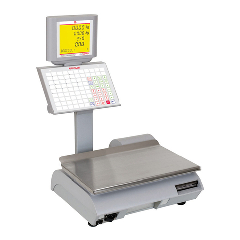
OHAUS RI Series User manual

RI Series
Maintenance manual
Range 15 kg d = 5g
Range 6 kg d = 2g

Maintenance manual RI Series
01/09/2006 Page - 2 -
Table of Contents
1. Introduction .....................................................................................................................................4
2. General characteristics ...................................................................................................................5
2.1 Metrological characteristics: .................................................................................................5
2.2 Electrical characteristics: ......................................................................................................5
2.3 RI Series keyboard:..............................................................................................................6
3. Installation.......................................................................................................................................8
4. RI Series exploded views..............................................................................................................10
4.1 Main shell equipped............................................................................................................10
4.2 Main shell equipped continued (29270000)........................................................................11
4.3 Final assembly with rear display.........................................................................................12
4.4 Final assembly with tower display.......................................................................................13
4.5 Fitted main shell..................................................................................................................14
4.6 Fitted display column..........................................................................................................15
4.7 Motor support equipped......................................................................................................16
4.8 Load cell support equipped.................................................................................................17
4.9 Fitted keyboard assembly...................................................................................................18
4.10 Fitted adjustable foot.......................................................................................................19
4.11 Fitted electrical socket panel...........................................................................................20
5. Seal...............................................................................................................................................21
6. Structure diagram..........................................................................................................................22
7. Diagnostic and analysis of failures................................................................................................23
7.1 Nothing happens when switching on the scales.................................................................24
7.2 Error message displaying:..................................................................................................25
7.3 Printing problems:...............................................................................................................26
8Replacements:..............................................................................................................................27
8.1 Replacing the A/D board and load cell assembly on RI Series...........................................28
8.2 Replacing the main board on RI Series..............................................................................30
8.3 Replacing the switching power supply unit on RI Series ....................................................31
8.4 Replacing the flexible keyboard on RI Series.....................................................................32
8.5 Replacing the thermal print head on RI Series...................................................................33
8.6 Replacing the fitted motor unit on RI Series.......................................................................34
8.7 Replacing the front display unit on RI Series......................................................................35
9. On site calibration procedure:.......................................................................................................36
9.1 "GEO" code modification: ...................................................................................................38
10. Technical data Test points / Settings:...........................................................................................39
10.1 Electrical characteristics:.................................................................................................39
10.2 The switching power supply unit (71207286)..................................................................42
10.3 Analogue/digital board.....................................................................................................43
10.3.1 Test points................................................................................................................43
10.3.2 Electrical diagram (29120154)..................................................................................44
10.4 RI Series CPU board (main board) .................................................................................45
10.4.1 The micro processor part..........................................................................................45
10.4.2 The printer part.........................................................................................................46
10.4.3 The display part:.......................................................................................................46
10.4.4 The communication part...........................................................................................47
10.4.5 The power supply part..............................................................................................47
10.4.6 Test points (main board 71207283)..........................................................................49
10.4.7 Diagrams..................................................................................................................50
11. Cables...........................................................................................................................................56
11.1 CPU board / Communication board (ref 71208130)........................................................56
11.2 Infra-red LED cable (Emitting cell) ref 71208141...........................................................57
11.3 Infra-red sensor cable (Receiving cell) ref 71208129.....................................................58

Maintenance manual RI Series
01/09/2006 Page - 3 -
11.4 Motor cable (ref 71208131)............................................................................................59
11.5 CPU board / Power supply cable (ref 71208132)............................................................60
11.6 CPU/front and rear displays cable (ref 71207314)..........................................................61
11.7 CPU board / column display cable (ref 71208142)..........................................................62
11.8 Wired key cable (ref 71207312)......................................................................................63
12. Networking....................................................................................................................................64
13. Error messages:............................................................................................................................65
14. Flash Loader" PC software: ..........................................................................................................67
15. RI SERIES protection kit against Electric Static Discharges (ESD)..............................................79
16. Spare parts list..............................................................................................................................83

Maintenance manual RI Series
01/09/2006 Page - 4 -
1. Introduction
This document is intended for After Sales Support technicians working on the versions of RI Series
and Atoll scales.
This manual gives details of the product codes of the parts and the make up of sub-assemblies. It
describes the maintenance operations most commonly performed on the scales. All questions relating
to the software are not treated in this manual but in the tutorial file "HeliosEng.chm"
This manual also lists the spare parts and sub-assemblies available as standard from OHAUS in the
appendix (see page 99). These spare parts and sub-assemblies are used to perform the main
maintenance operations described in the manual. You can order them by EDI, giving their respective
MTCIMF codes.
If you want to make any comments on or correct the contents of this manual, ask the MT-F Technical
Support team to contact the MTVIRY Design Department.

Maintenance manual RI Series
01/09/2006 Page - 5 -
2. General characteristics
RI Series is ticket printing scale that works in stand-alone or wired network mode.
Its main characteristics are:
- Three possible power sources:
- 90 to 264VAC / 47 to 440 Hz mains power supply.
- Cordless mode powered by an internal pack battery. The battery unit's charger is integrated
into the scales.
- 12 V or 24 V external battery power supply (car or truck battery).
- Base with quick adjustment large clearance feet.
- Large back-lit graphics screen with two levels light regulator, and four sizes of fonts.
- The keyboard is clear and readable, the keys can be assigned by programming and
customised according to the customer's wishes, numbers of sellers, PLU, functions, weights,
etc. and can be labelled.
- Simplified loading of the roll of paper.
- Networking Interconnection by cable for use in "guided selling" mode.
- Scrolling programming menus, for very simple use.
2.1 Metrological characteristics:
Only the weighing base is sealed.
an internal cable connects the sealed compartment to the main board.
- Maximum range: 15kg / Minimum scale: 5g / Maximum tare: 9.9995kg
or
(Maximum range: 6kg / Minimum scale: 2g / Maximum tare: 6.000kg
- Cummulative semi-automatic tare with subtractive effect.
- Predetermined tare (Numbered from 1 to 9) or associated with a PLU
- Unit price scale: 0.01€ (maximum unit price: 9999,99€)
- Price to pay scale: 0.01€ (maximum price to pay: 9999.99€)
2.2 Electrical characteristics:
The priority order in case of several supply at the same time is:
1- External battery 24 volts
2- Mains
3- External battery 12 volts
4- Internal battery pack
- Operating temperature range from -10°C to +40°C.
- Mains power consumption about between 10 to 50VA.
- Power supply voltage: 90 to 264VAC 47 to 440 Hz.
- Internal battery pack (11 x NI-MH elements): 13.2 V / 3Ah on RI Series,13.2 V / 3.8 Ah on
Atoll time life between 8 and 40 hours depending use of back-lit and printing.
- 12v or 24v external battery
- Up to 10 scales can be networked. A network can combine the multi-user and direct sales
(DS) modes.

Maintenance manual RI Series
01/09/2006 Page - 6 -
2.3 RI Series keyboard:
The keyboard has 80 keys, 4 configurations are available, numerical keys are situated at the centre
for keyboards type 1, 2 and 4 and on the right for type 3 and 5.
Keyboards type 4 and 5 are entirely definable by the user excepted for the following 20 keys which
have fixed location.
-10 numerical keys
-1 "V" key : Record seller or validate the functions
-1 "*" key : Total request
-1 "+/x" key : Record or multiply non weighed articles.
-1 "_" key : Subtract
-1 "T" key : Tare request
-1 "ANN" key : Cancel an entry
-1 "PLU" key : Switch to PLU mode (numerical inputs call up a PLU)
-1 "PLU" key : Switch to "Non PLU" mode (the numerical input enters a unit price)
-1 "C" key : Reset to zero or cancel an operation
-1 "," key : Decimal point.
- Keyboard number 1 and 2 :
6 direct users, up to 30 indirect users, 40 direct PLUs, 8 function keys.
The direct PLU keys (from 1 to 40) can be labelled. Blank labels supplied with the scales fit into
the areas delimited by the keys.
Programming keyboard on the opposite side of the working key board.
This side of the keyboard is used to program all the machine's functions.

Maintenance manual RI Series
01/09/2006 Page - 7 -
- Keyboard 3:
up to 30 indirect users, 48 directs PLUs, 12 function keys.
The direct PLU keys (from 1 to 48) can be labelled. Blank labels supplied with the scales fit into
the areas delimited by the keys.
Programming keyboard on the opposite side of the working key board.
This side of the keyboard is used to program all the machine's functions.

Maintenance manual RI Series
01/09/2006 Page - 8 -
- Keyboard 4:
the 20 location fixed keys have the same location as keyboard 1, all the other keys are
definable by the user depending of his wishes.
- Keyboard 5:
the 20 location fixed keys have the same location as keyboard 3, all the other keys are
definable by the user depending of his wishes.
3. Installation
1) Place the scales on a flat surface.
2) Set the scales level using the feet.
3) Plug the scales into a 230V mains socket or connect to an external battery.
4) Check that there is a roll of thermal paper in the printer. To do this, swing the keyboard
backwards. Lift the keyboard assembly vertically and insert a roll of paper if necessary (be careful
about the direction it unwinds in).
5) Close the keyboard until it clicks into place and press the switch (On/Off).
Maintenance:
1) Use the cleaning liquid to maintain the printer. Pour a few drops on some tissue and rub on the
ceramic part of the thermal print head. Only use the cleaning liquid supplied with the scales (isopropyl
alcohol). Any other product may cause premature wear of the printer.
Keyboard clips
Position of roll of
thermal paper Thermal head
RJ45 (PC)
2x RJ45(VA)

Maintenance manual RI Series
01/09/2006 Page - 9 -
2) The keyboard membrane, the keyboard grid, the plate, the casing and the display scales can be
cleaned using a moist sponge and soap (take care to switch off the machine before cleaning, remove
the mains plug). Do not use a scouring pad.

Maintenance manual RI Series
01/09/2006 Page - 10
-
4. RI Series exploded views
4.1 Main shell equipped
Ex
Safety
Metrology
Approval Notice

Maintenance manual RI Series
01/09/2006 Page - 11
-
4.2 Main shell equipped continued (29270000)
Marker Designation Article number
3 Battery pack (Saft) 71207297
8 Cable main board to com board 71208130
10 Main board 71207283
12 Switching power supply 71207286
14 Display LCD 71207313
17 Cable battery pack to main board 71208144
18 Power switch 71208127
26 Complete printing mechanism 71208137
28 Communication board 71207284
31 Power filter 71207310
53 Cable switching power supply to main board 71208132
54 Cable front or rear display 71207314

01/09/2006 Page - 12 -
4.3 Final assembly with rear display
Marker Designation Article number
1 Top plate equipped 71207281
Ex
Safety
Metrology
Approval Notice

01/09/2006 Page - 13 -
4.4 Final assembly with tower display
Marker Designation Article number
1 Top plate equipped 71207281
Ex
Safety
Metrology
Approval Notice

01/09/2006 Page - 14 -
4.5 Fitted main shell
Ex
Safety
Metrology
Approval Notice
Marker Designation Article number
1 Glass rear display Ohaus 72191975
3 128 x 128 LCD display 71207313
6 Cable front or rear display 71207314

01/09/2006 Page - 15 -
4.6 Fitted display column
Ex
Safety
Metrology
Approval Notice
Marker Designation Article number
1 Glass rear display Ohaus 72191975
3 128 x 128 LCD display 71207313
4 Cable tower display 71208142

01/09/2006 Page - 16 -
4.7 Motor support equipped
Ex
Safety
Metrology
Approval Notice
Marker Designation Article number
3 Silicone roll 71208138
7 Paper IR sensor with cable 71208129
10 Rubber roll ring 71208140

01/09/2006 Page - 17 -
4.8 Load cell support equipped
Ex
Safety
Metrology
Approval Notice
Marker Designation Article number
1 Equipped load cell support panel
2 Fitted load cell cross-piece
3 Shim between load cell and plate support
4 Washer DEC M6
5 Screw TBHC M 6x40
6 Spring ground contact with the pan 71208135
7 Unalterable label

01/09/2006 Page - 18 -
4.9 Fitted keyboard assembly
Ex
Safety
Metrology
Approval Notice
Marker Designation Article number
1 Keyboard silicone membrane 71207300
2 Intermediate sheet for keyboard nbr 1 71207302
2 Intermediate sheet for keyboard nbr 3 71208103
3 Foil film keyboard 71207301
4 Glass keyboard display "Ohaus" brand 72191976
15 Cable print head 71208146
16 Print head 71207282

01/09/2006 Page - 19 -
4.10 Fitted adjustable foot
Marker Designation Article number
1 Adjustable foot 71207299
2 Rubber pad
3 Self-locking ring DIA22
4 Nut HM12

01/09/2006 Page - 20 -
4.11 Fitted electrical socket panel
Marker Designation Article number
1 Mains filter
2 Bipolar switch
3 Electricity supply socket support panel
4 Screw TBHC M3X6
5 External battery (12v/24v) female socket
Table of contents
Other OHAUS Scale manuals

OHAUS
OHAUS ES30R User manual

OHAUS
OHAUS EXPLORER User manual

OHAUS
OHAUS Emerald User manual

OHAUS
OHAUS CS 2000 User manual

OHAUS
OHAUS CKW3R User manual

OHAUS
OHAUS Valor 2000W Series User manual

OHAUS
OHAUS PX Series User manual

OHAUS
OHAUS EXPLORER User manual

OHAUS
OHAUS Catapult 1000 User manual

OHAUS
OHAUS Valor V71P1502T User manual

OHAUS
OHAUS YA102 Gold User manual

OHAUS
OHAUS 5000 User manual

OHAUS
OHAUS Ranger User manual

OHAUS
OHAUS Scout STX Series User manual

OHAUS
OHAUS Defender D30BR User manual

OHAUS
OHAUS Dial-O-Gram User manual

OHAUS
OHAUS Defender 3000 Series User manual

OHAUS
OHAUS Valor 1000 User manual

OHAUS
OHAUS FD Series User manual

OHAUS
OHAUS TROOPER COUNT User manual