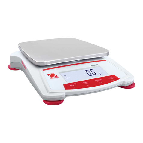
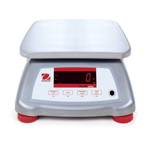
OHAUS JD500 User manual

1
Diamond Analytical
Carat Balance
Instruction Manual
OhausCorporation
19AChapinRoad
P.O.Box 2033
PineBrook, NJ07058-2033, USA

2
Marked with: EC Directive (Including applicable Standard
amendments)
73/23/EC EN61010-1:1993 + A2: 1995
Electrical equipment for use within Safety requirements for Electrical
specified voltage limits Equipment for Measurement Control
Laboratory Use Part 1: General
Requirements
89/336/EC EN55011:1991 (cla B)
Electromagnetic compatibility EMC Emissions residential commercial
and light industry.
EN50082-2:1995 + A1:1998
(minimal requirement )
EMC Immunity: Minimum test requirements.
EN61000-3-2:1995 + A1:1998 + A2:
1998; EN61000-3-3:1995
EMC Part 3 (for equipment rated input
current < or=16A)
Limits- Section 2: Limits for harmonic
current emissions
Limits- section 3: Limitation of voltage
fluctuations and flicker in low voltage
supply systems
LasttwodigitsoftheyearinwhichtheCEmarkingwasaffixed: 99
Additional Standard
CAN/CSA-C22.2 No. 1010.1-92; UL Std. No. 3101-1
Safety requirements for Electrical Equip. for measurement Control and
Laboratory Use Part 1; General Requirements
FCC, Part 15, cla A Emission
AS/NZS2064-1/2 AS/NZS4252.1 Emission and Immunity
C US
Ohaus Corporation, 19A Chapin Road, P.O. Box 2033, Pine Brook, NJ, 07058-2033, USA
Declaration of Conformity We, Ohaus Corporation, declare under our sole responsibility
that the balance models listed below marked with “CE” - are in conformity with the
directives and standards mentioned.
Balance model (s) JD500
.++

3
ISO 9001 Registration for Ohaus Corporation. Ohaus Corporation, USA, was ex-
amined and evaluated in 1994 by the Bureau Veritas Quality International, BVQI,
and was awarded ISO 9001 registration. This certifies that Ohaus Corporation,
USA, has a quality system that conforms with the international standards for qual-
ity management and quality assurance (ISO 9000 series). Repeat audits are car-
ried out by BVQI at intervals to check that the quality system is operated in the
proper manner.
FCCNOTE:THIS EQUIPMENTHASBEENTESTEDAND FOUNDTO COMPLY
WITHTHELIMITS FORACLASSA DIGITALDEVICE,PURSUANTTO PART 15
OF THE FCC RULES.
THESE LIMITS ARE DESIGNED TO PROVIDE REASONABLE PROTECTION
AGAINST HARMFUL INTERFERENCE WHEN THE EQUIPMENT IS OPER-
ATED IN A COMMERCIAL ENVIRONMENT.THIS EQUIPMENT GENERATES,
USES, AND CAN RADIATE RADIO FREQUENCY ENERGY AND, IF NOT IN-
STALLED AND USED IN ACCORDANCEWITHTHE INSTRUCTION MANUAL,
MAY CAUSE HARMFUL INTERFERENCE TO RADIO COMMUNICATIONS.
OPERATION OF THIS EQUIPMENT IN A RESIDENTIAL AREA IS LIKELY TO
CAUSE HARMFUL INTERFERENCE IN WHICH CASE THE USER WILL BE
REQUIREDTO CORRECT THE INTERFERENCE AT HIS OWN EXPENSE.
Ted Xia
President
Ohaus Corporation Pine Brook NJ USAn
THIS DIGITAL APPARATUS DOES NOT EXCEED THE CLASS A LIMITS FOR
RADIO NOISE EMISSIONS FROM DIGITAL APPARATUS AS SET OUT INTHE
INTERFERENCE-CAUSINGEQUIPMENTSTANDARDENTITLED“DIGITAL AP-
PARATUS”, ICES-003 OF THE DEPARTMENT OF COMMUNICATIONS
CANADA.
CET APPAREIL NUMERIQUE RESPECTE LES LIMITES DE BRUITS
RADIOELECTRIQUES APPLICABLES AUX APPAREILS NUMERIQUES DE
CLASSEAPRESCRITES DANS LANORMESUR LE MATERIELBROUILLEUR:
“APPAREILS NUMERIQUES”, NMB-003 EDICTEE PAR LE MINISTRE DES
COMMUNICATIONS.
Unauthorized changes or modifications to this equipment are not permitted.

4
TABLE OF CONTENTS
DESCRIPTION .................................................................................................5
UNPACKING.....................................................................................................5
INSTALLATION .................................................................................................5
Setting Up and Leveling the Balance ................................................5
Pan Installation ..................................................................................5
Connecting Power..............................................................................6
Weigh Below Hook ............................................................................6
Security Bracket .................................................................................6
TURNING THE BALANCE ON .........................................................................6
TURNINGTHE BALANCE OFF ........................................................................6
WEIGHING ........................................................................................................6
TARING ............................................................................................................7
MENU DESCRIPTION......................................................................................7
ACTIVATING UNITS..........................................................................................7
PRINT MENU....................................................................................................8
SETTING PRINT MENU FUNCTIONS .............................................................8
Entering the Print Menu .....................................................................8
Setting Baud Rate ..............................................................................9
Setting Parity ......................................................................................9
Setting Data........................................................................................9
Setting Stop Bit...................................................................................9
Setting Print Modes ............................................................................9
CALIBRATION ............................................................................................... 10
Calibration Masses ......................................................................... 10
Span Calibration ............................................................................. 10
Linearity Calibration........................................................................ 11
PRINTING ...................................................................................................... 11
RS232 INTERFACE....................................................................................... 11
Hardware ........................................................................................ 11
RS232 Commands ......................................................................... 12
Output Formats................................................................................ 12
CARE AND MAINTENANCE ......................................................................... 13
TROUBLESHOOTING ................................................................................... 13
Error Codes ..................................................................................... 13
ACCESSORIES ............................................................................................. 14
SPECIFICATIONS.......................................................................................... 14
Admissible Ambient Conditions...................................................... 14
WARRANTY................................................................................................... 15
5
DESCRIPTION
Carefully unpack the balance, verify that all items are on hand. Save the
packing material for transporting the balance.
UNPACKING
All balances are shipped with the following components:
• Weighing Platform • Instruction manual • Power adapter
Your Ohaus Analytical balance is a precision weighing instrument, designed to
provide years of service. Simple three button operation allows for the selection of
units, calibration and printing parameters. A standard RS232 interface permits
communication to an external printer or computer. Power is supplied through an
AC adapter.
INSTALLATION
For best performance, the balance should be used in a clean, stable environment.
Do not use the balance in environments with excessive drafts, near magnetic
fields or equipment that generates magnetic fields, rapid temperature changes,
vibrations or corrosive vapors.
Setting Up and Leveling the Balance
For exact horizontal positioning, the balance is equipped with a level indicator
and two leveling feet located at the rear of the balance.
Position the balance in the intended operating location. Adjust the leveling feet at
the rear of the balance until the air bubble in the indicator is centered.
NOTE: The instrument should be leveled each time its location is changed.
BUBBLE LEVEL
LEVELING FEET (2)
Pan Installation
Slide open the door and insert the platform in the balance. The balance is now
ready for operation.

6
INSTALLATION (Cont.)
Connecting Power NOTICE:
The socket/outlet must be installed near
the equipment and shall be easily accessible.
Connect the AC Adapter cord to the connector located at the rear of the balance
and to a suitable power source.
Weigh Below Hook
For below balance weighing applications (eg. density determination), a weigh
below hook is installed at the bottom of the balance and is part of the balance. To
use, remove the protective plug cover located at the bottom of the balance. The
balance should then be supported on an elevated level surface which allows
access to the weigh below hook. The balance should be releveled. Measure-
ments are made by the use of a fine wire attached to the internal weigh below
hook.
CAUTION:
Do not attempt to remove the weigh below hook from the balance as the
balance may be damaged.
Security Bracket
A security bracket is provided at the rear of the balance which allows the balance
to be secured by the optional cable and lock accessory.
TURNING THE BALANCE ON
Press O/T ON. All segments will appear briefly followed by a software revision
number. Allow 20 minutes warm-up time.
TURNING THE BALANCE OFF
To turn the balance OFF, press and hold MODE OFF until the display indicates
OFF
,thenrelease.
1. If it is necessary to rezero the display, momentarily press O/T ON.
2. Place item(s) to be weighed on the pan and read the weight on the display.
The stability indicator appears when the reading is stable.
WEIGHING
*

7
TARING
Whenweighingitemsthat mustbeheld inacontainer,taringsubtractsthe container's
weight from the total weight on the pan. Remember, the weight of the container
and the material it holds must not exceed the capacity of the balance.
1. With an empty container on the pan, press O/T ON to zero the display.
2. As material is added to the container, the net weight is displayed. Tared
weight remains in balance memory until O/T ON is pressed again.
3. If the container is no longer used and is removed from the balance, the
display indicates a negative weight which was the container’s weight.
Press O/T ON to zero the display.
MENU DESCRIPTION
The User Menu permits you to activate weighing units, select printing parameters,
perform Linearity calibration and set tone settings. Each menu item is covered in
a separate procedure in this manual.
To enter the menu, start with the balance OFF, press and hold O/T ON until
MENU
is displayed, then release it.
MENU
UNITS - g, ct, ozt, GN, dwt, Hong Kong Taels, Singapore Taels,
Taiwan Taels, set each to ON or OFF.
LIN - Performs linearity calibration. (See calibration in later section)
SYS - Permits setting tone ON or OFF with each keystroke.
PRINT - Permits setting communication parameters.
MENU - Exit menu and return to weighing mode.
END
ACTIVATING UNITS
1.With the balance OFF, press and hold O/T ON until
MENU
is displayed,
then release,
UNITS
is displayed.
2. Press O/T ON,
On g
is displayed. To turn this unit of measure
ON or OFF, press MODE OFF to select on or off condition.
3. To advance to the next weighing unit, press O/T ON, then press MODE OFF
to select ON or OFF. You must continue until
END
appears.
4. When
END
is displayed, press O/T ON to store unit selections.
5. To exit the menu, repeatedly press MODE OFF until
MENU END
is dis-
played, then press O/T ON. Balance returns to a weighing mode.

8
SETTING PRINT MENU FUNCTIONS
This procedure permits you to set one or all of the RS232 communication param-
eters. Each parameter can be entered and set individually.
ENTERINGTHE PRINT MENU
1. Start with the balance OFF. Press O/T ON until
MENU
is displayed.
2. Press MODE OFF until
Print
is displayed.
3. With
Print
displayed, press O/T ON until
Reset
is displayed. You may
now select to change any of the parameters in Reset, Baud Rate, Parity
Data Bits, Stop Bits, Stable Data, Auto Print, or End which saves all settings.
4. By repeately pressing MODE OFF, you can enter any one of the above print
menu items. See following procedures.
PRINT MENU
The Print menu is used to configure and customize the RS232 interface parameters
for your requirements. The following table shows the sequence in which submenus
appear on the Print Menu. Factory settings are in bold.
PRINT MENUTABLE
Baud Rate Specifies baud rate of either 600, 1200, 2400, 4800, or 9600.
Data Bits Specifies number of data bits, 7 or 8.
Parity Bit Specifies parity type, Odd, Even, or None.
Stop Bits Specifies the number of stop bits, 1 or 2.
Auto Print Prints stable data when display changes 5 counts. OFF is
default.
Stable Data Enables/disables printing stable data only feature. OFF is
default.
End Used to exit the Print menu and store your selections.

9
Setting Baud Rate
Press O/T ON, until
bd 2400
is displayed. Using the MODE OFF button, you can
select baud rates of 600, 1200, 2400, 4800 or 9600. Once you have selected the
proper baud rate for your system, press O/T ON, the display advances to
PAR no
(parity).
Setting Parity
Repeatedly press MODE OFF, to select either no, odd or E for even. Once the
desired parameter is selected, press O/T ON, the display advances to
DATA 7
.
Setting Data
Pressing the MODE OFF button allows the selection of DATA 7 or DATA 8. Once
the desired parameter is selected, press O/T ON, the display advances to
STOP 2
.
Setting Stop Bit
Pressing MODE OFF, you can select STOP 1 or 2. Press O/T ON, the display
advances to
STBL ON
.
Setting Print Modes
The balance offers a choice of manually printing only stable or all data (STBL ON/
OFF) at any time by pressing the PRINT button or printing stable readings auto-
matically (AUTO ON/OFF). Thedefaultsettingforautomatic stable readingsisOFF.
Only one of these may be set on at a time.
Stable Data On or Off
When
STBL ON
is displayed, press MODE OFF to select ON or OFF, then press
O/T ON ,
AUTO OFF
is displayed.
Auto Print On or Off
With Auto Print ON, the balance automatically prints stable data when the display
changes byat least five counts.Press MODE OFF andselectONor OFF, then press
O/T ON,
END
is displayed. To save settings, press O/T ON,
MENU END
is dis-
played. Press O/T ON to return to weigh mode.
ENTERINGTHE PRINT MENU (Cont.)
SETTING PRINT MENU FUNCTIONS (CONT.)

10
CALIBRATION
Your Ohaus Balance was calibrated before shipment, however, calibration can be
affected by changes in location, temperature, or rough handling. Your balance
can be calibrated in two ways: Span calibration or Linearity calibration. Span
calibration resets the balance's weighing range using two weight values: zero
and a weight value at or near the balance's capacity. Linearity calibration mini-
mizes deviation between actual and displayed weights within the balance's weigh-
ing range. Three weight values are used:zero, a weight value within the balance's
weighing range and a weight value at or near the balance's specified capacity.
CALIBRATIONMASSES
Before beginning calibration, make sure masses are available. If you begin cali-
bration and realize calibration masses are not available, exit the procedure by
pressing and holding MODE OFF until balance returns to weigh mode. The bal-
ance will retain previously stored calibration data. Calibration should be per-
formed as necessary to ensure accurate weighing. Masses required to perform
the procedures are listed in the following table.
CALIBRATION MASSES
LINEARITY SPAN ONLY
MASSES MASS
50g/100 100g
SPANCALIBRATION
1. With the balance turned ON, press and hold O/T ON until
CAL
is displayed.
2. Release O/T ON ,
-C-
is momentarily displayed followed by the value of the
calibration mass which is to be placed on the pan.
Do not disturb the balance when
-C-
is displayed.
Incorrect calibration may result.
3. Place the indicated span calibration mass on the pan.
4. Press O/T ON,
-C-
is momentarily displayed, then the weight of the mass
on the pan is displayed.
5. Remove the calibration mass from the pan. The balance is now calibrated
and returns to the weighing mode.
Masses must meet or exceed ASTM Class 1Tolerance.
Calibration masses are available as accessories.

11
LINEARITYCALIBRATION
1.With the balance OFF, press and hold O/T ON until
MENU
is displayed, then
release it and
UNITS
is displayed. Press MODE OFF,
LIN
is displayed.
2. Press O/T ON,
-C-
is displayed followed by the value of the first mass which
must be placed on the pan.
3. Place the required mass on the pan and momentarily press O/T ON,
-C-
is
displayed followed by the value of the next mass to be placed on the pan.
Do not disturb the balance while
-C-
is displayed.
4. Place the second required mass on the pan and momentarily press O/T
ON,
-C-
is displayed. When the weight on the pan is displayed with the
stability indicator, the balance is calibrated and returns to the weighing mode.
5. Remove the calibration masses from the pan.
PRINTING
To print the balance display results, press PRINT until
-P-
is displayed then re-
lease.
RS232 INTERFACE
When the balance is connected directly to a printer, displayed data can be output
at any time by using the Auto Print feature.
Connecting the balance to a computer enables you to operate the balance from
the computer, as well as receive data such as displayed weight and weighing
mode. The following sections describe the hardware and output signal formats
provided with the balance.
HARDWARE
On the rear of the balance, a 9-pin subminia-
ture “D” connector is provided for interfacing
to other devices.The pinout and pin connec-
tions are shown in the table and illustration.
1 N/C
2 Data Out (TXD)
3 Data In (RXD)
4 N/C
5 Connected to pin 8.
6 N/C
7 Ground
8 Connected to pin 5.
9* N/C
12345
6789

12
RS232COMMANDS
All communication is accomplished using standard ASCII format. Only the charac-
ters shown in the following table are acknowledged by the balance. Any other
commands, control characters or spaces are ignored. Commands sent to the
balance must be terminated with a carriage return (CR) or carriage return-line
feed (CRLF). For example, a tare command should appear as shown in the dia-
gram. Data output by the balance is always terminated with a carriage return - line
feed (CRLF).
TARE COMMANDTARE COMMAND
TARE COMMAND Field: T CR LF
Length: 1 1 1
RS232 INTERFACE
OUTPUTFORMATS
Data output can be initiated in one of two ways: 1) Using the Auto Print feature; 2)
Sending a print command (“P”) from a computer.
RS232 COMMAND DATATABLE
Command
Character Description
P Print command
T Tare command
? Displays current mode
XS X=0 (zero) Stable off
XS X=S Stable on (default setting in balance)
XS X=A Auto print on stabilty
NOTE: Print commands entered through the computer are temporary.
When the balance is turned off, it will return to balance menu settings
when turned on again.

13
ERRORCODES
CARE AND MAINTENANCE
To keep the balance operating properly, keep the housing and platform clean. If
necessary, a cloth dampened with a mild detergent may be used. Check under the
sub platform for debris and remove. Keep calibration masses in a safe dry place.
TROUBLESHOOTING
When a problem occurs using the balance, the display will indicated an error code.
Review the listed codes and follow instructions to correct the problem.
Err 2.0 Stability error. Check if balance is located near vibrating equipment or if air
currents are affecting it.
Err 3.0 Calibration error (wrong mass). Incorrect or no calibration mass used when
performing calibration procedure. Error will flash momentarily, then balance
will use previous calibration data. Recalibrate correctly.
Err 4 Invalid data checksum in type or adjust data. Return balance for servicing.
Err 8.4 Over or under load. Sample being weighed exceeds the capacity of the
balance. If error occurs when the sample is within the balance capacity,
balance may be incorrectly calibrated. An underload such as the pan off of
the balance could also display Err8.4. Recalibrate the balance.
Err 9 Internal data error. Return balance for servicing.
Err 9.8 Invalid checksum in calibration or setup data. The balance may need
recalibration, particularly linearity calibration. If the error persists after
recalibration, the balance must be serviced.
SYMPTOM
No Display.
Incorrect weight
reading.
Calibration proce-
dure does not
work.
Unable to display
weight in a particu-
lar weighing unit.
Balance won't
store selections
made in menu.
PROBABLE CAUSE
Power Adapter not
connected.
Balance out of cali-
bration.
Balance was not
rezeroed before
weighing.
Incorrect calibration
masses being used.
Weighingunit not ac-
tivated in menu.
END selection was
not used to exit
menu.
REMEDY
Connect AC Adapter.
Calibrate the bal-
ance.
Press TARE ON with
no weight on the pan,
then weigh item.
Use correct masses.
Use Units menu to
set desired units ON
(see menu).
You must use END to
exit each menu and
save selections.
TROUBLESHOOTINGTABLE

14
SPECIFICATIONS
MAXCAPACITY (ct) 500
READABILITYd(mct) 1
WEIGHINGUNITS grams, carats, oz t, grains, taels (3)
REPEATABILITY(STDDEV) (mct) 1
LINEARITYUP(mct) 1
STABILIZATIONTIME (s) 4
TARERANGE Full Capacity by Subtraction
OPERATINGHUMIDITYRANGE 10-85% non-condensing
PLATFORMSIZE(in/cm) 3.5/9
DIMENSIONS(WxHxD)(in/cm) 8.5x12.3x13.5/21.7x31x34.3
ITEMNUMBER JD500
ACCESSORIES
Part No.
50g Calibration Mass 49054-11
100g Calibration Mass 49015-11
Security Device 76288-01
Impact Printer SF42
RS232 Interface Cable, to SF42 printer 80500570
Admissible ambient conditions Use only in closed rooms
Temperature range: 50°F to 86°F / 10°C to 30°C
Atmospheric humidity: 80% rh @ to 30°C
Voltage fluctuations: -15% +10%
Installation category: II
Pollution degree: 2
Power supply voltage: 8-14V ac, 50/60Hz, 6VA or 9.5-20V dc, 6W
Power Adapter: AP3405 120V, 60Hz 10W
AP3405E 230V, 50Hz 80mA
AP3405B 240V, 50Hz 80mA

15
LIMITED WARRANTY
Ohaus products are warranted against defects in materials and workmanship from
the date of delivery through the duration of the warranty period. During the warranty
period Ohaus will repair, or, at its option, replace any component(s) that proves to be
defective at no charge, provided that the product is returned, freight prepaid, to Ohaus.
This warranty does not apply if the product has been damaged by accident or misuse,
exposed to radioactive or corrosive materials, has foreign material penetrating to the
inside of the product, or as a result of service or modification by other than Ohaus. In
lieu of a properly returned warranty registration card, the warranty period shall begin
on the date of shipment to the authorized dealer. No other express or implied warranty
is given by Ohaus Corporation. Ohaus Corporation shall not be liable for any conse-
quential damages.
As warranty legislation differs from state to state and country to country, please
contact Ohaus or your local Ohaus dealer for further details.

16
OhausCorporation
19AChapinRoad
P.O. Box 2033
PineBrook, NJ07058-2033, USA
Tel:(973)377-9000
Fax:(973)593-0359
Withoffices worldwide.
www.ohaus.com
OhausCorporation 2002, allrights reserved.
P/N80250951A PRINTED INCHINA
Table of contents
Other OHAUS Scale manuals

OHAUS
OHAUS 5000 User manual

OHAUS
OHAUS Defender 6000 Indicators User manual

OHAUS
OHAUS TA152 User manual

OHAUS
OHAUS GT4100DG User manual

OHAUS
OHAUS Ranger R31P(E)1502 User manual

OHAUS
OHAUS Scout pro User manual

OHAUS
OHAUS SCOUT PRO User manual

OHAUS
OHAUS Valor 3000 User manual

OHAUS
OHAUS TP200S User manual

OHAUS
OHAUS Traveler User manual

OHAUS
OHAUS Ranger Count 1000 Series User manual

OHAUS
OHAUS I-C52M100L User manual

OHAUS
OHAUS CS Series User manual

OHAUS
OHAUS Navigator Series User manual

OHAUS
OHAUS 4000W Series User manual

OHAUS
OHAUS ES series User manual

OHAUS
OHAUS Valor 1000 User manual

OHAUS
OHAUS VN Series User manual

OHAUS
OHAUS 5000 User manual

OHAUS
OHAUS Pioneer User manual