Ohlins TTX25 Instruction manual

TTX25 Pressurized Front Fork Cartridge Kit
Workshop Manual

2
3
SAFETY PRECAUTIONS
IN THIS MANUAL
© Öhlins Racing AB. All rights reserved. Any
reprinting or unauthorized use without the written
permission of Öhlins Racing AB is prohibited.
Safety Symbols
In this manual, mounting instructions and
other technical documents, important
information concerning safety is
distinguished by the following symbols:
The Safety Alert Symbol means: Warning!
Your safety is involved.
Warning!
The Warning Symbol means: Failure to
follow warning instructions can result in
severe or fatal injury to anyone working with,
inspecting or using the shock absorber, or
to bystanders.
Caution!
The Caution Symbol means: Special
precautions must be taken to avoid damage
to the shock absorber.
Note!
The Note Symbol indicates information that
is important regarding procedures.
Note!
The front fork is a very important part of the
vehicle and will affect the stability.
Note!
Read and make sure that you understand the
information in this manual and the mounting
instructions before you use this product. If you
have any questions regarding installation or
maintenance please contact an Öhlins dealer.
Note!
Öhlins Racing AB can not be held responsible
for any damage to the front fork, vehicle, other
property or injury to persons, if the instructions
for installing and maintenance are not followed
exactly.
Warning!
This product was developed and designed
exclusively for a specific vehicle model and shall
only be installed on the intended vehicle model
in its original condition as delivered from the
vehicle manufacturer.
Warning!
After installing this product, take a test ride at
low speed to make sure that your vehicle has
maintained its stability.
Warning!
If the suspension makes an abnormal noise,
or the function is irregular, or if you notice any
leakage from the product, please stop the
vehicle immediately and return the product to an
Öhlins Service Centre.
Note!
When working on this product, always see
the Vehicle Service Manual for vehicle specific
procedures and information.
Note!
When working with the cartridge kit always
make sure you have a clean working space.
1 Replace Spring 4
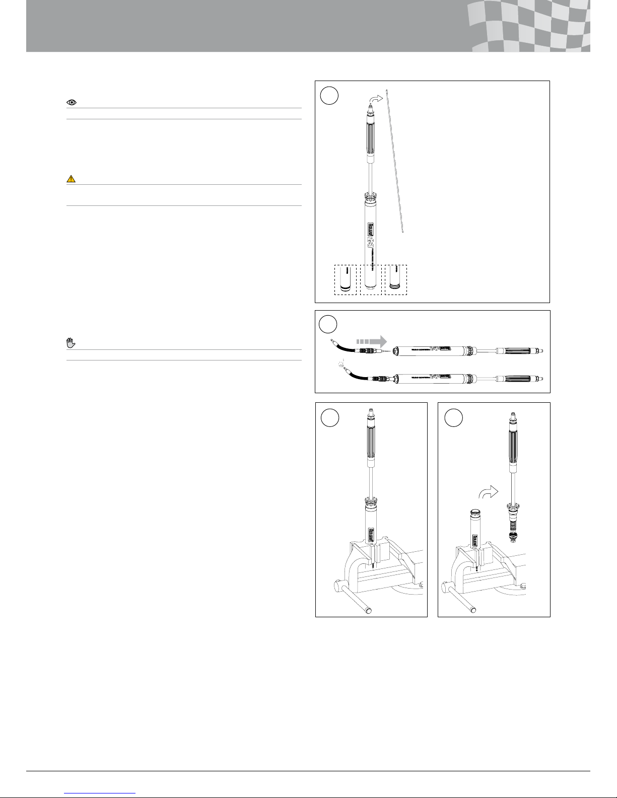
2 Remove Cartridge from Front Fork 5
2.11A Front Fork with Thread connection 6
2.11B Front Fork with Bottom Screw connection 6
2.11C Front Fork with BPF (Big Piston Fork) 6
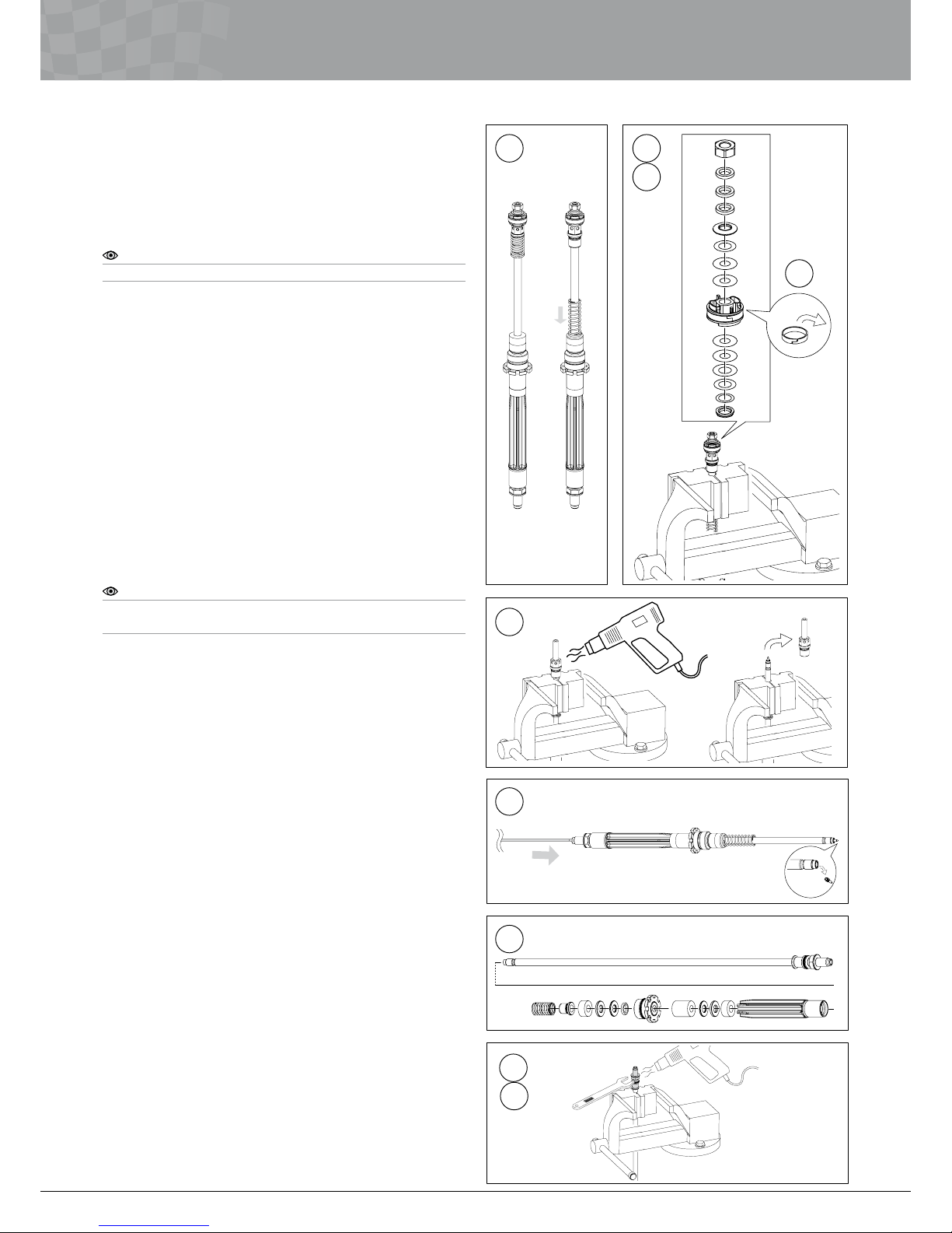
3 Disassemble Cartridge 7
3.1 Remove Shaft 7
3.2 Disassemble Shaft 8
3.3 Disassemble Seal head 9
3.4 Disassemble Dividing Piston 9
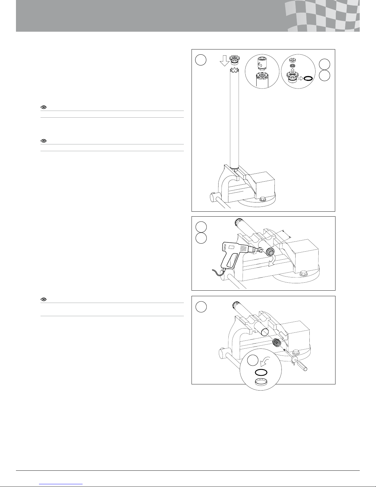
4 Assemble Cartridge 10
4.1 Assemble Dividing Piston 10
4.2 Assemble Seal Head 10
4.3 Assemble Shaft 11
4.4 Mount Shaft 12
5 Fill Oil 13
6 Reinstall Cartridge into Fork Leg 14

2
3
TOOLS
1 2 3
4 5 6
7 8 9
10
13
16
14
17
15
18
11 12
1 00146-01 Assembly lubricant – Red grease
2 00716-01 Snub nose
3 00720-02 Measure Pin (6mm)
4 00727-02 Soft jaws 10/12
5 00727-09 Soft jaws 28/36
6 00797-08 Top cap tool
7 01460-68 Dividing piston positioning tool (tube length 32mm)
8 01765-03 Pull-up tool (length 300mm)
9 01781-01 Gas lling device assy (gas needle housing 01779-02)
10 01797-05 Seal head tool 33.5 (compress top out spring)
11 01797-07 Seal head tool 36 (tighten with torque)
12 01797-09 Seal head tool 36 (long fangs)
13 01820-24 Filling machine assembly adaptor M4
14 01840-xx Öhlins Filling Machine (and Manual 07221-02)
15 01860-04 End cap tool
16 02810-01 Clip for 01765-03
17 04705-03 U-spanner 19mm
18 01309-01 Öhlins Front Fork uid
19 FGR1XX Spec. card

4
5
1 REPLACE SPRING
1 Replace Spring
Note!
You can replace the Spring with the front fork still mounted on the
motorcycle.
1.1
Use appropriate tool to release the spring preload completely. Turn
the Preload adjuster counter clockwise as far as possible.
Caution!
Do not use the Preload adjuster to tighten or loosen the Top cap from
the fork leg.
1.2
Loosen the screws that hold the fork legs in the upper triple clamp.
1.3
Use tool 00797-08 together with appropriate tool. Loosen the Top
cap from the outer fork leg.
1.4
Use appropriate tool on the Top cap preload adjuster and tool
04705-03 on the Shaft extension. Remove the Top cap from the
Shaft extension.
Note!
When removing tool 04705-03 hold your hand against the Spring
support and Spring to prevent them from being pushed out by the
spring force.
1.5
Remove tool 04705-03.
1.6
Remove the Spring support and the Spring. Use a wire with a hook
and carefully pull up the Preload tube.
1.7
Check the oil level according to Mounting Instructions.
Note!
Use Öhlins Front Fork fluid 01309-01 only.
1.8
Mount the Preload tube, the new Spring and the Spring support in
the front fork.
Note!
Mount the Spring with the marking facing up.
1.9
Mount the Top cap to the Shaft extension.
Tightening torque 15Nm
1.10
Apply Assembly lubricant to the Top cap thread and O-ring. Use
tool 00797-08. Mount the Top cap into the outer fork leg, with the
fork leg fully extended.
Tightening torque 10Nm
Note!
It is important that the fork leg is fully extended.
1.11
Tighten the upper triple clamp.
Tightening torque according to vehicle service manual
1.12
Adjust the spring preload according to recommendations in the
Mounting Instructions.
1.1 1.2
1.3
Spring
support
Spring
Preload
tube
1.6
1.4
1.8

4
5
2 REMOVE CARTRIDGE FROM FRONT FORK
2 Remove Cartridge from Front Fork
2.1
Use appropriate tool to release the spring preload completely. Turn
the Preload adjuster counter clockwise as far as possible.
Caution!
Do not use the Preload adjuster to tighten or loosen the Top cap from
the fork leg.
2.2
Loosen the screws that hold the fork legs in the upper triple clamp.
2.3
Use tool 00797-08 together with appropriate tool. Loosen the Top
cap from the outer fork leg, approximately ½ turn.
2.4
Loosen the screws that hold the fork legs in the lower triple clamp.
2.5
Remove the front fork from the motorcycle.
2.6
Fasten the fork leg in a vice.
2.7
Use appropriate tool on the Top cap preload adjuster and tool
04705-03 on the Shaft extension. Remove the Top cap from the
Shaft extension.
Note!
When removing tool 04705-03 hold your hand against the Spring
support and Spring to prevent them from being pushed out by the
spring force.
2.8
Remove tool 04705-03.
2.9
Remove the Spring support and the Spring. Use a wire with a hook
and carefully pull up the Preload tube.
2.10
Remove the front fork from the vice.
2.11
Pour out all oil from the front fork.
2.1 2.2
2.3 2.6
Spring
support
Spring
Preload
tube
2.9
2.7

6
7
2 REMOVE CARTRIDGE FROM FRONT FORK
Note!
Please see the Mounting Instructions for the three different types of
connections between the cartridge and the front fork.
To remove the Cartridge from the fork leg, continue below
according to your connection type.
Type A – Cartridge with thread connection
Type B – Cartridge with bottom screw connection
Type C – Cartridge with BPF (Big Piston Fork) damping system
2.12A Front Fork with Thread Connection
2.12.1A
Use tool 01797-07 to loosen the Seal head from the Cylinder tube
extension just enough to align the grooves on the Seal head with
the grooves on the Cylinder tube extension.
Caution!
Do not loosen the Seal head more than is necessary to align the
grooves. If you loosen the Seal head too much the oil may leak.
2.12.2A
Use tool 01797-09 to loosen the Cartridge from the front fork.
Note!
Ensure that tool 01797-09 grips both the Seal head and the Cylinder
tube extension.
2.12.3A
Remove the Cartridge from the front fork.
Note!
Ensure that the Shim between the Adaptor and fork bottom follows
when removing the Cartridge.
2.12B Front Fork with Bottom Screw Connection
2.12.1B
Use tool 01797-07 to loosen the Seal head from the Cylinder tube
extension just enough to align the grooves on the Seal head with
the grooves on the Cylinder tube extension.
Caution!
Do not loosen the Seal head more than is necessary to align the
grooves. If you loosen the Seal head too much the oil may leak.
2.12.2B
Loosen the bottom screw.
2.12.3B
Remove the cartridge from the front fork.
Note!
If needed, use tool 01797-09 to keep the cartridge from turning.
2.12C Front Fork with BPF (Big Piston Fork)
2.12.1C
Use tool 01797-07 to loosen the Seal head from the Cylinder tube
extension just enough to align the grooves on the Seal head with
the grooves on the Cylinder tube extension.
Caution!
Do not loosen the Seal head more than is necessary to align the
grooves. If you loosen the Seal head too much the oil may leak.
2.12.2C
Use tool 01797-09 to loosen the Cartridge from the front fork.
2.12.3C
Remove the Cartridge from the front fork.
A B C
A
A
A
B
B
C
C
2.12.1
2.12.2
2.12.3
2.12.2

6
7
3 DISASSEMBLE CARTRIDGE KIT
3 Disassemble Cartridge Kit
Note!
Chapters 3, 4 and 5 are applicable for all connection types.
3.1 Remove Shaft
3.1.1
Remove the Adjustment rod from the Shaft.
Warning!
Releasing the reservoir gas pressure can be hazardous. Do not perform
any kind of service until gas pressure is completely released.
3.1.2
Use tool 01781-01. Release gas pressure.
3.1.3
Use tool 00727-09 and fasten the Cartridge in a vice in a vertical
position.
3.1.4
Use tool 01797-07. Loosen the Seal head from the Cylinder tube
extension.
3.1.5
Remove the Shaft assembly from the Cylinder tube.
Caution!
Be careful not to damage the Piston ring.
3.1.6
Remove the Cylinder tube from the vice.
3.1.7
Pour out all oil from the Cylinder tube.
3.1.1
3.1.2
3.1.3 3.1.5

8
9
3.2 Disassemble Shaft
3.2.1
Pull off the Top out spring from the Piston holder.
3.2.2
Use tool 00727-02. Fasten the Shaft in a vice. Fasten the soft jaws
close to the Piston holder.
Note!
Note the orientation of and order between the parts before removal.
3.2.3
Use appropriate tool to remove the Nut on the Piston holder and
remove the Piston, Shims and setting parts from the Piston holder.
3.2.4
Remove the Piston ring from the Piston.
3.2.5
Use a heat gun to loosen the Piston holder from the Shaft.
Use appropriate tool to remove the Piston holder from the Shaft.
3.2.6
Remove the Shaft from the vice.
3.2.7
Use the Adjustment rod to push out the Needle from the Shaft.
3.2.8
Pull off the Top out spring, Sleeve, Spacers, O-ring, Seal head,
Bump rubber, Spacers and Guide sleeve from the Shaft.
Note!
Be careful not to damage the Seal when pulling the Seal head over the
Shaft’s thread.
3.2.9
Use tool 00727-02. Fasten the Shaft in a vice near the Shaft
extension.
3.2.10
Loosen the Shaft extension from the Shaft. Use a heat gun
to loosen the Loctite. Use tool 04705-03 to loosen the Shaft
extension.
3.2.11
Remove the O-ring from the Shaft extension.
3 DISASSEMBLE CARTRIDGE
3.2.1 3.2.2
3.2.3
3.2.5
3.2.7
3.2.8
3.2.9
3.2.10
3.2.4

8
9
3.3.1 3.3.2
3.3.3
3 DISASSEMBLE CARTRIDGE
3.3 Disassemble Seal head
3.3.1
Use tool 01797-07, fasten tool in vice. Use appropriate tool
together with tool 01860-04 to loosen the End cap from the Seal
head.
3.3.2
Remove the Seal from the Seal head.
Note!
Be careful not to scratch the Seal surfaces.
3.3.3
Remove the O-ring.
Note!
If the Bushing is damaged replace the Seal head and Bushing.
3.4.1
3.4.2
3.4.3
approx 50 mm
3.4 Disassemble Dividing Piston
3.4.1
Use tool 00727-09. Fasten the Cylinder tube assembly in a vice
approximately 50 mm from the Adaptor.
3.4.2
Use heat gun to soften the Loctite used between Outer cylinder
tube and Adaptor. Loosen the Adaptor from the Outer cylinder tube.
Use appropriate tool for the Adaptor.
3.4.3
Use tool 00720-02. Pull out the Dividing piston.
Note!
Be careful not to damage the O-ring and the Piston ring when pulling
over the Outer cylinder tube’s thread.
3.4.4
Remove the O-ring and the Piston ring.
3.4.4

10
11
4 ASSEMBLE CARTRIDGE
4 Assemble Cartridge Kit
4.1 Assemble Dividing Piston
4.1.1
Apply Assembly lubricant on the O-ring. Mount the O-ring on the
Dividing piston.
4.1.2
Mount the Piston ring on the Dividing piston.
4.1.3
Apply a thin layer of Assembly lubricant on the inside of the Outer
cylinder tube.
4.1.4
Mount the Dividing piston into the Outer cylinder tube, push it as far
in the Outer cylinder tube as possible.
Caution!
Be careful not to damage the O-ring and the Piston ring on the Outer
cylinder tube’s thread.
4.2 Assemble Seal Head
4.2.1
Use Assembly lubricant on the O-ring. Mount the O-ring on the Seal
head.
4.2.2
Mount the Seal.
Note!
Ensure to mount the Seal correctly. See figure.
Caution!
When mounting be careful not to scratch the Seal surface.
4.2.3
Use tool 01797-07 and tool 01860-04 together with appropriate
tool. Mount the End cap.
Tightening torque 25Nm
Loctite243
4.1.1
4.1.4
4.2.3
4.2.1
4.2.2
4.1.2

10
11
4 ASSEMBLE CARTRIDGE
4.3 Assemble Shaft
4.3.1
Mount the O-ring on the Shaft extension.
4.3.2
Use tool 00727-02. Fasten the Shaft in a vice near the Shaft
extension end of the Shaft.
4.3.3
Use appropriate torque wrench to mount the Shaft extension on the
Shaft.
Tightening torque 15 Nm
Loctite 2701
Note!
Ensure to mount the Shaft correctly. The small orifice towards the Shaft
extension.
4.3.4
Remove the Shaft from the vice.
4.3.5
Mount the Guide sleeve on the Shaft. Ensure that the Guide sleeve
connects to the Shaft extension. You will hear a noticeable click.
4.3.6
Mount the Spacers, Bump rubber and Seal head on the Shaft.
Note!
When mounting be careful not to damage the Seal surface.
Note!
Ensure the Sleeve is mounted into the Top out spring.
4.3.7
Mount the O-ring, Spacers and Sleeve with Top out spring on the
Shaft.
4.3.8
Use Assembly lubricant on the O-ring. Mount the Needle together
with the O-ring inside the Shaft.
4.3.2
4.3.5
4.3.6
4.3.7
4.3.1
4.3.8

12
13
4.3.9
Use tool 00727-02. Fasten the Shaft in a vice near the Piston holder
end of the Shaft.
4.3.10
Use a 14 mm long socket to mount the Piston holder on the Shaft.
Tightening torque 15 Nm
Loctite 243
4.3.11
Use a 14 mm socket to mount the Piston, Shims, settings parts and
nut.
Note!
Make sure to mount the parts in the same orientation and order of the
parts as they were at removal.
Tightening torque 7 Nm
Loctite 243
4.3.12
Connect the Top out spring onto the Piston holder. You will hear a
noticeable click.
4.3.13
Mount the Piston ring on the Piston.
4 ASSEMBLE CARTRIDGE
4.3.9 4.3.10
4.3.11
4.4.1
4.4.2
4.3.12
4.4 Mount Shaft
4.4.1
Use tool 00727-09. Fasten the Cylinder tube assembly in a vice in
an upright position, approximately 100mm from the top.
4.4.2
Use Assembly lubricant on the Seal head thread and O-ring. Use
tool 01797-07 to install the Shaft assembly in the Cylinder tube
assembly.
Tightening torque 20 Nm
4.3.13
approx 100 mm

12
13
5 Fill Oil
Note!
This procedure requires Öhlins Filling Machine. See separate manual for
Öhlins Filling Machine for proper use.
5.1
Use tool 01797-05 and tool 02810-01 to compress the Top out
spring with tool 01765-03. Keep the Top out spring compressed
during remaining steps of the lling procedure.
Note!
Ensure that the Top out spring is fully compressed.
5.2
Turn the Shaft assembly to a horizontal position in the vice.
5.3
Use tool 01460-68 as a spacer in the cylinder tube to achieve
correct position for the Dividing piston. Use Adaptor without
O-ring as a stop by screwing it all the way into the Cylinder tube.
Handtighten only.
Note!
O-ring shall not be installed on the Adaptor.
5.4
Remove the Fill screw. Check the O-ring. Replace if damaged.
5.5
Use tool 01820-24 together with the lling machine and mount it in
the lling hole in the Cylinder tube extension. Fill the system (See
Öhlins Filling Machine Manual).
5.6
Disconnect lling machine and remove tool 01820-24.
5.7
Mount the Fill screw together with the O-ring. Tightening torque 3.5
Nm
5.8
Remove the Adaptor and tool 01460-68.
Warning!
It is important that you remove the Dividing piston positioning tool.
5 FILL OIL
5.1
5.2
5.3
5.4
5.5
5.8
approx 100 mm
approx
100 mm

14
15
5.9
Put the O-ring on the Adaptor and install the Adaptor. Use
Assembly lubricant on the O-ring. Clean the thread and apply
Loctite.
Tightening torque 40 Nm
Loctite 243
5.10
Remove tool 02810-01, 01797-05 and 01765-03.
5.11
Use tool 01781-01. Fill gas to 6 Bar.
5.12
Mount the Adjustment rod in the Shaft.
5 FILL OIL
5.10
5.12

14
15
6 REINSTALL CARTRIDGE INTO FORK LEG
6
Mount the Cartridge Kit into the front fork. See Mounting
Instructions for correct procedure.

Your Öhlins retailer:
Öhlins Workshop Manual TTX25 Pressurized Cartridge Kit_0 | Issued 20111-04-11 | © 2011 Öhlins Racing AB
Phone: +46 (0)8 590 025 00
Fax: +46 (0)8 590 025 80
www.ohlins.com
Öhlins Racing AB
Box 722
SE-194 27, Upplands Väsby
Sweden
Table of contents
Other Ohlins Motorcycle Accessories manuals

Ohlins
Ohlins HD 159 User manual

Ohlins
Ohlins HO 944 User manual

Ohlins
Ohlins WR 450 F - 2-TRAC 2005 User manual

Ohlins
Ohlins HUSABERG MX 2000 User manual

Ohlins
Ohlins FKS 503 User manual

Ohlins
Ohlins SU 789 User guide

Ohlins
Ohlins HA 192 User manual

Ohlins
Ohlins FSK 105 User manual

Ohlins
Ohlins FGR 156 User manual

Ohlins
Ohlins AP 840 User manual

Ohlins
Ohlins HO 819 User manual

Ohlins
Ohlins HO 810 User manual

Ohlins
Ohlins SD 021 User manual

Ohlins
Ohlins HO 1072 User manual

Ohlins
Ohlins HD 907 User manual

Ohlins
Ohlins YA 469 User manual

Ohlins
Ohlins FGRT 219 User manual

Ohlins
Ohlins BM606 User manual

Ohlins
Ohlins SD510 User guide

Ohlins
Ohlins KA 736 User manual