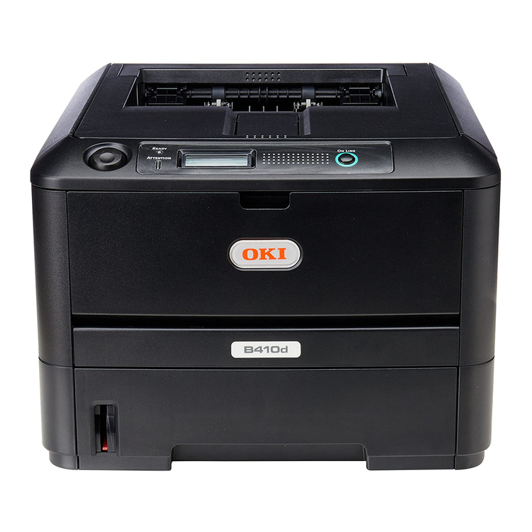
Oki B431L6 User manual

OEL
Maintenance Manual
B401/B411L6/B431L6
Revision 1
Rev Date Oki Data Corporation
1 2012-02-14
Name
B401/B411/B431
Maintenance Manual
This document is “OKI DATA – CONFIDENTIAL”
Only persons and parties authorised by OKI DATA have
permissions to access this document.
This document should not be accessed by any parties
without the approval of OKI DATA.
Anyone who is found to be contradicting the above may be subject to legal action.

44983601TH Rev.1 ii /
Oki Data CONFIDENTIAL
Document Revision History
Rev. No. Date Corrected items Person in
charge
No. Page Description of change
1 2012-02-14 ISSUE EMD12 T.Ishikuro

44983601TH Rev.1 iii /
Oki Data CONFIDENTIAL PREFACE
B401d B401dn B411d B411dn
Engine speed (letter/A4) TBD/29 TBD/29 35/33 35/33
Resolution Max. resolution 2400 x 600 dpi 2400 x 600 dpi 2400 x 600 dpi 2400 x 600 dpi
Emulation Standard PCL6/SIDM PCL6/SIDM PCL6/SIDM PCL6/SIDM
Option N/A N/A N/A N/A
Operation panel LCD display 16 character x 2 16 character x 2 16 character x 2 16 character x 2
Switch 1 (online/offline) 1 (online/offline) 1 (online/offline) 1 (online/offline)
LED lights 2 2 2 2
Input tray (Manual/Auto) Single sheet manual feed Single sheet manual feed Single sheet manual feed Single sheet manual feed
Input tray (1st bin)(20 lb paper) 250 sheets 250 sheets 250 sheets 250 sheets
Input tray (2nd bin)(20 lb paper) N/A N/A 530 sheets 530 sheets
Maximum Input capacity 251 251 781 781
Interface USB 2.0
Parallel
Ethernet N/A N/A
Auto Duplex Standard Standard Standard Standard
Monthly Duty Cycle Maximum 80,000 pages 80,000 pages 80,000 pages 80,000 pages
Starter Toner@ISO19752 1,000 1,000 2,000 2,000
Toner life@ISO19752 1,500/2,500 1,500/2,500 3,000/4,000 3,000/4,000
Drum life 25,000(3P/J) 25,000(3P/J) 30,000(3P/J) 30,000(3P/J)
Dimensions (inch./mm) Width 15.2”/387mm 15.2”/387mm 15.2”/387mm 15.2”/387mm
Depth 14.3"/364mm 14.3"/364mm 14.3"/364mm 14.3"/364mm
Height 9.6"/244.5mm 9.6"/244.5mm 9.6"/244.5mm 9.6"/244.5mm
Sales Territories
ODA 100v N/A N/A
ODA 200v N/A N/A
OEL
AOS 1byte N/A N/A
Korea N/A N/A
Japan N/A N/A N/A
China N/A N/A N/A
PREFACE
This Maintenance Manual describes the maintenance methods in the printer field for the maintenance
personnel. In addition, regarding the handling and operating method of the printer, please refer to the "User’s
Manual".
The differences between various types of printers described in this Maintenance Manual are as follows.

44983601TH Rev.1 iv /
Oki Data CONFIDENTIAL
B431d B431dn
Engine speed (letter/A4) 40/38 40/38
Resolution Max. resolution 1200 x 1200 dpi 1200 x 1200 dpi
Emulation Standard PCL6/PS3/SIDM PCL6/PS3/SIDM
Option N/A N/A
Operation panel LCD display 16 character x 2 16 character x 2
Switch 6 6
LED lights 2 2
Input tray (Manual/Auto) 100 sheets Multi Purpose
Tray 100 sheets Multi Purpose
Tray
Input tray (1st bin)(20 lb paper) 250 sheets 250 sheets
Input tray (2nd bin)(20 lb paper) 530 sheets 530 sheets
Maximum Input capacity 880 880
Interface USB 2.0
Parallel
Ethernet N/A
Auto Duplex Standard Standard
Monthly Duty Cycle Maximum 80,000 pages 80,000 pages
Starter Toner@ISO19752 2,000 2,000
Toner life@ISO19752 3,000/4,000/10,000 3,000/4,000/10,000
Dram life 30,000(3P/J) 30,000(3P/J)
Dimensions (inch./mm) Width 15.2”/387mm 15.2”/387mm
Depth 14.3"/364mm 14.3"/364mm
Height 9.6"/244.5mm 9.6"/244.5mm
Sales Territories
ODA 100v
ODA 200v
OEL
AOS 1byte
Korea N/A
Japan N/A
China N/A
Note! •Itisprohibitedtoreprintentireorpartialofthecontentwithoutpriorconsent.
• For the reason of printer improving and manual content revising, the content of this
maintenance manual may change without any warning in the future.

44983601TH Rev.1 v /
Oki Data CONFIDENTIAL Contents
1. CONFIGURATION........................................................................................................1-1
1.1 System Configuration .......................................................................................................................1-1
1.2 Printer Configuration .........................................................................................................................1-2
1.3 Optional Configuration.......................................................................................................................1-4
1.4 Specification......................................................................................................................................1-5
1.5 Printing display..................................................................................................................................1-8
1.5.1 VCCI label, Serial No.label.......................................................................................................1-8
1.5.2 Warning label............................................................................................................................1-8
1.5.3 Warning / Caution display.........................................................................................................1-9
2. Operational explanation................................................................................................2-1
2.1 Electrophotographic process mechanism ........................................................................................2-1
2.2 Printing process ................................................................................................................................2-7
2.3 Toner entrance detection.................................................................................................................2-11
3. Parts replacement.........................................................................................................3-1
3.1 Preparation for parts replacement.....................................................................................................3-1
3.2 Parts layout .......................................................................................................................................3-3
3.3 Parts replacement method................................................................................................................3-5
3.3.1 LED Head..................................................................................................................................3-6
3.3.2 Roller-Transfer...........................................................................................................................3-7
3.3.3 Duplex Belt................................................................................................................................3-8
3.3.4 Cover-Side-R.............................................................................................................................3-9
3.3.5 Cover-Side-L...........................................................................................................................3-10
3.3.6 CU-Board................................................................................................................................3-11
3.3.7 PWB unit - ACDC Switch........................................................................................................3-12
3.3.8 DC Motor ................................................................................................................................3-13
3.3.9 Hopping / MPT / Regist Clutch ...............................................................................................3-14
3.3.10 HV-Board / Motor-FAN ..........................................................................................................3-15
3.3.11 Cover Assy OPE....................................................................................................................3-16
3.3.12 Ope PCB Assy ( B431 ) ..........................................................................................................3-17
3.3.13 Cover Assy Stacker.................................................................................................................3-18
3.3.14 Stacker Cover..........................................................................................................................3-20
3.3.15 Fuser Assy..............................................................................................................................3-21
3.3.16 MPT Assy , Manual Assy).......................................................................................................3-22
3.3.17 Cover Assy Rear.....................................................................................................................3-23
3.3.18 Guide Eject Lower Assy..........................................................................................................3-25
3.3.19 Eject Motor..............................................................................................................................3-26
3.3.20 Plate Side R Assy / Plate Side L Assy / Front Assy................................................................3-27
3.3.21 Plate Side L Assy....................................................................................................................3-28
3.3.22 Plate Side R Assy...................................................................................................................3-29
3.3.23 Roller Regist............................................................................................................................3-30
3.3.24 Roller Feed Assy.....................................................................................................................3-31
Contents

44983601TH Rev.1 vi /
Oki Data CONFIDENTIAL Contents
3.3.25 Lever In Sensor / Lever WR Sensor / /Photo Interrupter.........................................................3-32
3.3.26 Paper feeding roller (Roller-Pick-Up,Roller-Feed-NOW,Roller-Assy-MPT).............................3-33
3.3.27 Frame-Assy-Retard , Spring-Retard........................................................................................3-35
3.4 Lubricating points............................................................................................................................3-36
4. ADJUSTMENT..............................................................................................................4-1
4.1 Category and function of maintenance mode ...................................................................................4-1
4.1.1 User maintenance mode (Administrator Menu) .......................................................................4-1
4.1.2 System maintenance mode (System maintenance menu)........................................................4-6
4.1.3 Self-diagnostic Mode...............................................................................................................4-11
4.1.4 Energy conservation mode setting..........................................................................................4-26
4.1.5 EEPROM Initialization.............................................................................................................4-27
4.2 Adjustment at part replacement......................................................................................................4-28
4.2.1 EEPROM data upload / download method .............................................................................4-28
5. Periodic Maintenance...................................................................................................5-1
5.1 Periodic Replacement Parts..............................................................................................................5-1
5.2 Cleaning............................................................................................................................................5-1
5.3 Cleaning of LED lens array ...............................................................................................................5-1
5.4 Cleaning the Feed rollers and the Retard roller ................................................................................5-2
6. Procedures for Repairing..............................................................................................6-1
6.1 Troubleshooting.................................................................................................................................6-1
6.2 Points to be checked before modifying printing problems.................................................................6-1
6.3 Points to be checked when the printing problems are modified........................................................6-1
6.4 Preparation for Troubleshooting.........................................................................................................6-1
6.5 Troubleshooting Flow ........................................................................................................................6-2
6.5.1 LCD Status Message/ Trouble Table .........................................................................................6-2
6.5.2 LCD Message Troubleshooting...............................................................................................6-10
6.5.3 Print Troubleshooting...............................................................................................................6-18
7. Connection Diagram.....................................................................................................7-1
7.1 Connection diagram..........................................................................................................................7-1
7.2 Board Layout.....................................................................................................................................7-2
7.3 Resistance value.............................................................................................................................7-16
Appendix A Centronics Parallel Interface.........................................................Appendix A-1
Appendix B USB Interface................................................................................Appendix B-1
Appendix C Maintenance Manual for Second Tray unit................................... Appendix C-1
1 Overview .............................................................................................................................Appendix C-1
1.1 Function ........................................................................................................................Appendix C-1
1.2 Exterior and Parts Name...............................................................................................Appendix C-1
2. Description for Operation of Second Tray unit.....................................................................Appendix C-2
3. Part Replacement................................................................................................................Appendix C-3
3.1 Precautions on replacing parts......................................................................................Appendix C-3
3.2 Arrangement of Parts....................................................................................................Appendix C-4
3.3 How to Replace Parts....................................................................................................Appendix C-5
3.3.1 Roller-Pick-Up, Roller-Feed-Now...........................................................................Appendix C-6
44983601TH Rev.1 vii /
Oki Data CONFIDENTIAL Contents
3.3.2 Guard-Connector, Connector (9715S-08Z02-G4C)...............................................Appendix C-7
3.3.3 Board-GOG ...........................................................................................................Appendix C-8
3.3.4 CONN Cord-AMP8P-AMP8P ................................................................................Appendix C-9
3.3.5 Gear-Assy-Clatch (Hop, Regist), Motor-Pulse.....................................................Appendix C-10
3.3.6 Frame-Assy-Retard, Spring-Retard.....................................................................Appendix C-12
4. Cleaning of Paper Feed Roller and Separation Roller ......................................................Appendix C-13
5. Procedure for Troubleshooting...........................................................................................Appendix C-14
5.1 Precautions for Troubleshooting..................................................................................Appendix C-14
5.2 Preparation before Troubleshooting ............................................................................Appendix C-14
5.3 Troubleshooting Method..............................................................................................Appendix C-15
5.3.1 LCD Status Message List....................................................................................Appendix C-16
6. Connection Diagram..........................................................................................................Appendix C-18
6.1 Connection diagram....................................................................................................Appendix C-18
6.2 Board Arrangement.....................................................................................................Appendix C-18
Appendix D Network Interface......................................................................... Appendix D-1

Oki Data CONFIDENTIAL 1. CONFIGURATION
44983601TH Rev.1 1-1 /
1. CONFIGURATION
1.1 System Configuration
As the diagram 1.1 shows, for the standard configuration printer is configured by controller unit and
engine unit.
Operator panel board
LED:2, SW:1(B401d/B401dn/
B411d/B411dn)
LED:2, SW:6(B431d/B431dn)
LED head
LCD CENTRONICS
Main print circuit board
USB 2.0
LAN
(10BASE-T/100BASE-TX)
(B401dn/B411dn/
B431dn only)
Toner cartridge
Image drum cartridge
High voltage power supply uint Low voltage
power supply unit Fuser unit
Main DC Motor
2nd tray unit*
Additionally installed memory*
Hopping clutch (1st)
Register clutch
Hopping clutch (MPT)
(B431d/B431dn only)
Paper end sensor
Eject stepping motor
Eject sensor
Rear cover open sensor
Halogen lamp
FUSE
Thermostat
Temperature sensor
Exhaust FAN
Cassette presence
- absence sensor HUM / TEMP
sensor Duct FAN
Power supply
FAN
Stacker cover open
SW
Faceup stacker open sensor
Transfer roller
AC inlet AC-SW
Board
Fuse Relay terminal
Entrance sensor
Write sensor
Toner sensor
board
*:except B401
Figure1-1

Oki Data CONFIDENTIAL 1. CONFIGURATION
44983601TH Rev.1 1-2 /
1.2 Printer Configuration
The printer main unit includes the following hardware parts.
• Electrophotographicprocessingpart
• Paperfeedingpart
• Controller
• Operationalpart
• Powersupplyunit
Figure1-2
B401d/B401dn/B411d/B411dn
Note! •Fuser-Assy has to be replaced by Assy unit.
• ItisforbiddentodisassembleFuser-AssyorreusethedisassembledFuser-Assy.
The configuration of printer main unit is shown as diagram 1-2~1-4

Oki Data CONFIDENTIAL 1. CONFIGURATION
44983601TH Rev.1 1-3 /
B431d/B431dn
Figure1-3
25

Oki Data CONFIDENTIAL 1. CONFIGURATION
44983601TH Rev.1 1-4 /
1.3 OptionalConguration
The options attached to the printer are as follows. These options can be ordered respectively for the
printer main unit.
(1) Second tray unit (B411/B431)
(2) Additionally installed memory (B411/B431)
Domestic oriented printer only use 64MB,128MB,256MB.

Oki Data CONFIDENTIAL 1. CONFIGURATION
44983601TH Rev.1 1-5 /
1.4 Specification
(1) Type Desktop
(2) Dimension 244.5mm (Height) x 387mm (Width) x 364 (Depth)
:B4011d/B401dn/B411d/B411dn/B431d/B431dn
(3)Weight Approx.11.6kg(Itincludestheweightoftheprintermainunitandconsumables.
Itdoesn'tincludetheweightofoptionsandpaper.)
(4)Developmentmethod Draytype–Elementdevelopingmethod
Exposuremethod LEDHeadmethod
(5) Paper type, thickness, Size
Recommendedpaper Normalpaper………….ExcellentpaperA4andExcellentwhiteA4
OHPSheet…………….Sumitomo3MPP2500
Labelpaper…………….KokuyoLBP-A693
Category Size unit: mm (inch) Thickness
Normal Paper
A4 210×297 Weight 55~140kg(64~163g/m2)
For double-side printing, weight55~105kg
(64~122g/m2)
Tray1,Width100~215.9,Length148~355.6
Tray2,Width148~215.9,Length210~355.6
MP Tray or Manual Tray,
Width86~215.9,Length140~1320.8
A5 148×210
A6 105×148
B5 182×257
Letter 215.9×279.4(8.5×11)
Legal (13inch) 215.9×330.2(8.5×13)
Legal (13.5inch) 215.9×342.9(8.5×13.5)
Legal (14inch) 215.9×355.6(8.5×14)
Statement 139.7× 215.9(5.5×8.5)
Executive
184.15×266.7(7.25×10.5)
16K184
×260mm
184
×260
16K195
×270mm
195
×270
16K197
×273mm
197
×273
Custom Width86~215.9
Length140~355.6
Postcard Postcard 100×148 Postcard
Return Postcard 148×200
Envelope
Envelope1(Chou#3) 120×235 The envelope should be using 85g/m2paper. The
flap of the envelope Chou type should not be with
fold, the flap of the envelope you should be clearly
folded.
Envelope2(Chou#4) 90×205
Envelope3(You#4) 105×235
Com-9 98.4×225.4(3.875×8.875) The envelope should be using 24 lb. paper and
the flap part of it should be clearly folded.
Com-10 104.78×241.3(4.125×9.5)
DL 110×220(4.33×8.66)
C5 162×229(6.4×9)
C6 114×162(4.49×6.38)
Monarch 98.4×190.5(3.875×7.5)
Custom Width86~215.9
Length140~355.6
LabelPaper A4 210×297 0.1~0.15mm
Letter 215.9×279.4(8.5×11)
OHPSheet A4 210×297 0.1~0.15mm
Letter 215.9×279.4(8.5×11)
Partial Printing
Paper −−Weight 55~140kg(64~163g/m2)
Paper for Color
Printing −−Weight 55~140kg(64~163g/m2)

Oki Data CONFIDENTIAL 1. CONFIGURATION
44983601TH Rev.1 1-6 /
(6) Paperfeedingmethod/Ejectingmethod
: Itispossibletouseit.
× : Itisnotpossibletouseit.
: Itispossibletouseitbyapartofsize
*1: Multipurpose tray can be used for B431.
*2: Face-uppaperejectingisnotavailableatautomaticdouble-sideprinting.
*3: Tray 2 (The second tray unit) is optional for B411/B431.
*4: Tray 1 is 100 to 215.9 mm in width and 148 to 355.6 mm in length. Tray 2 is 148 to 215.9 mm in width and 210 to 355.6 mm in
length.Eachofthemulti-purposetraysandmanualfeedertraysis86to215.9mminwidthand140to1320.8mminlength.
*5: IfMediumHeavy,HeavyorUltraHeavyisspeciedformediaweightwhereA5,A6,Postcard,orEnvelopeisspeciedfor
media size, the print speed is reduced.
*6: Ifprintedsheetsofpapergetcurledandcannotbeejectedsmoothly,changetheselectionforejectiontoface-down.
*7: Ifpaperiswarped(curled)signicantly,changetheselectionforejectiontoface-up.
(7) Printing speed Continuous printing(Maximum) : 29 ppm (B401)/33 ppm (B411)/38 ppm (B431)
*A4, At copy mode, First try
For the resolution degree of 600 x 2400, if to
enhance the printing quality, the printing speed
changes to be decreased.
Warm up time : Approx. 20 second (22°C, 100V)
Type Thickness
(Weight:Kg) Size
Paper feeding Method Paperejecting
method Double-side print
Paper
cassette
MP
Tray*1Manual Face
up*6Face
down*7
Automatic double-side print*2Manual double-side print
Tray
1Tray
2*3Tray
1Tray
2*3MP
Tray*1Manual Tray
1Tray
2*3MP
Tray*1Manual
Normal
paper
Weight
55~105kg
A4
B5
Letter
Executive
16K184×260mm
16K195×270mm
16K197×273mm
×
Legal
(13
inch
)
Legal
(13.5
inch
)
Legal
(14
inch
)× ×
A5*5× × × ×
Statement
A6*5× × × × × ×
Custom*4
Width
86
~
215.9mm
Length
140
~
1320.8mm
×
Weight
106~140kg
A4
B5
Letter
Executive
Legal
(13
inch
)
Legal
(13.5
inch
)
Legal
(14
inch
)
A5
Statement
A6
Custom*4
Width
86
~
215.9mm
Length
140
~
1320.8mm
× × × × × × × × × × ×
Postcard
*5
Refer to pr-
evious page Postcard/
Return postcard × × × × × × × × × × ×
Envelope
Refer to
previous
page
Envelope1(CHOU3)
Envelope2(CHOU4)
Envelope3(YOU4)
Com-9
Com-10
DL
C5
C6
Monarch
Custom
Width 86~215.9mm
Length140~355.6mm
× × × × × × × × × × ×
Lable
paper 0.1~0.5mm A4/Letter × × × × × × × × × × ×
OHP 0.1~0.5mm A4/Letter × × × × × × × × × × ×

Oki Data CONFIDENTIAL 1. CONFIGURATION
44983601TH Rev.1 1-7 /
(8) Paper feeding method Automatic feeding
(9) Paperejectingmethod Facedown(Rearejecting)/Faceup(Frontejecting)
(10) Resolution (Max.) 2400 × 600 dots / inch (B401/B411)
1200 × 1200 dots / inch (B431)
(11) Inputelectricity AC100V±10V,50/60Hz±1Hz(B411/B431)
(12) Electricityconsumption Upandrunning:Maximum 900W,
Average 510W (25°C)(B401/B411)
550W (25°C)(B431)
Ready and waiting: Average 70W (25°C)
Power-saving mode: (Without option) Approx. 6.5W or less
(With option) Approx. 7.5W
(13)Temperature and Humidity
(14)Operatingnoise InPrinting :Averagebelow53dBAforSLOW.(B401/B411)
(RageAbased :Averagebelow54dBAforSLOW.(B431)
onJISZ9831) Readyandwaiting:Averagebelow30dBAforSLOW.
At power save : No sound (Background level)
(15) Consumables Toner cartridge : Approx. 1,500 piece / Approx. 2,500 piece / Approx. 3,000 piece
/Approx. 4,000 piece/Approx. 10,000 piece(A4 ISO/IEC 19752
Continuous printing as printing paten. But, except the 1st Toner
cartridge)
Imagedrum :Approx.44,000piece(Continuouslysingle-sideprintingofA4)
Cartridge : Approx. 30,000 piece (Single-side3pages/job)At Power save off.
Approx. 1,7500 piece (Single-side1page/job)At Power save off.
*B401Approx.25,000piece(Single-side3pages/job)
At Power save off..
10
28
32
Temperature (°C)
20 80 Relative humidity (%)
6QBOESVOOJOH
Tenperature Humidity
Upand
running 10~32 20~80%RH (Relative Humidity) No condensation.
However, Maximum temperature of wet ball should
be 25°C.
Power switch
off 0~43 10~90%RH (Relative Temperature) No
condensation. However, Maximum temperature of
wet ball should be 26.8°C.
Keeping -10~43 10~90%RH (Relative Humidity) No condensation.
However, Maximum temperature of wet ball should
be 26.8°C.

Oki Data CONFIDENTIAL 1. CONFIGURATION
44983601TH Rev.1 1-8 /
1.5 Printing display
1.5.1 VCCIlabel,SerialNo.label
The VCCI label and Serial No. label have been attached on the specified part of printer as shows
below.
1.5.2 Warning label
Warninglabelhasbeenattachedonthepartofprinterthatmaycauseinjurytotheoperator.
Maintenance must be performed following the indication of the warning label.
Made in
A F 8 5 1 2 3 4 5 6 A 0

Oki Data CONFIDENTIAL 1. CONFIGURATION
44983601TH Rev.1 1-9 /
1.5.3 Warning / Caution display
The following warning / caution are displayed on the electrical power / sensor board.
Note! •There is a risk of electric shock in the middle of the heat sink and transformer. Be sure to check
before touch it.
• Itmayhappenthattheelectricityhasstillleftontheelectricalcircuitevenafterthefuseopened.
Warning /
Caution content record
High voltage power board
Component side Soldering side
Low voltage power board
Warning / Caution content record
Heat sink
Heat sink
Heat sink

Oki Data CONFIDENTIAL 2. Operational explanation
44983601TH Rev.1 2-1 /
2. Operational explanation
2.1 Electrophotographic process mechanism
(1) Electrophotographic process
The following describes the overview of electrophotographic process.
1. Charging
Equally charge the surface of image drum by implying negative voltage to the charged roller due to
negative charge.
2. Exposure
The light from LED Head is exposed on the negative-charged surface of image drum. The surface
electrical potential of the exposed part of image drum surface becomes lower. Then forms electrostatic
latent image.
3. Development
Negative-charged toner is attracted to the electrostatic latent image due to electrostatic while touching
the image drum. Then forms viewable image.
4. Transfer
Overlap paper on the surface of OPC drum, from the backside of paper transfer toner image to the
paper by applying electrical charge by transfer roller.
5. Fusing
The toner image that is transferred to paper is fused on paper by heat and pressure.
6. Drum cleaning
The cleaning blade scrapes off the toner that was not transferred and remains on the image drum.
7. Static elimination
Residual potential on the image drum is removed.

Oki Data CONFIDENTIAL 2. Operational explanation
44983601TH Rev.1 2-2 /
1. Charging
Charge the image drum surface by implying voltage to the charged roller that contacts the image drum
surface.
Image drum
Charged roller
Power
2. Exposure
The light emitting from the LED Head will be exposed to the negative charged image drum. When the
surface electric potential of exposed part of the image drum goes to decrease, the electrostatic latent
image complying with image signal is formed.
Image drum is coated by basic layer (UL), charge generating layer (CGL), charge transferring layer (CTL)
on the basic material aluminum. The thickness of the organic light sensor (OPC) that is consisted by
CTL and CGL is approximate 20µm.
Charged roller
LED head LED head
Image drum Image drum
Paper
Power

Oki Data CONFIDENTIAL 2. Operational explanation
44983601TH Rev.1 2-3 /
3. Image development
Toner is attracted to the electrostatic latent image on the image drum surface, then the electrostatic
latent image changes to toner image.
1 As the roller on the supply spot of toner rotates while scrubbing the image-developing roller,
fiction electricity occurs between the image developing roller and toner; toner is attracted to
the image-developing roller.
Image drum
Charged roller Image developing plate
Toner supply roller
Image
developing
roller
2. The toner that has been attracted to the image-developing roller is dropped down to the
developing plate to make a thin toner film on the image developing roller side.
3 The toner is attracted by the exposed part (Low electrical potential part) of the image drum
when the image drum contact the image developing roller, so as to see the electrostatic latent
image.

Oki Data CONFIDENTIAL 2. Operational explanation
44983601TH Rev.1 2-4 /
Note! The necessary bypass voltage in image processing is impressed on the toner feeding roller
and image developing roller as show below.
Image drum
Basic material
Toner feeding roller
While the cover is closed it will be
connected and bias will be applied
.
Image developing roller
This manual suits for next models
6
Table of contents
Other Oki Printer manuals