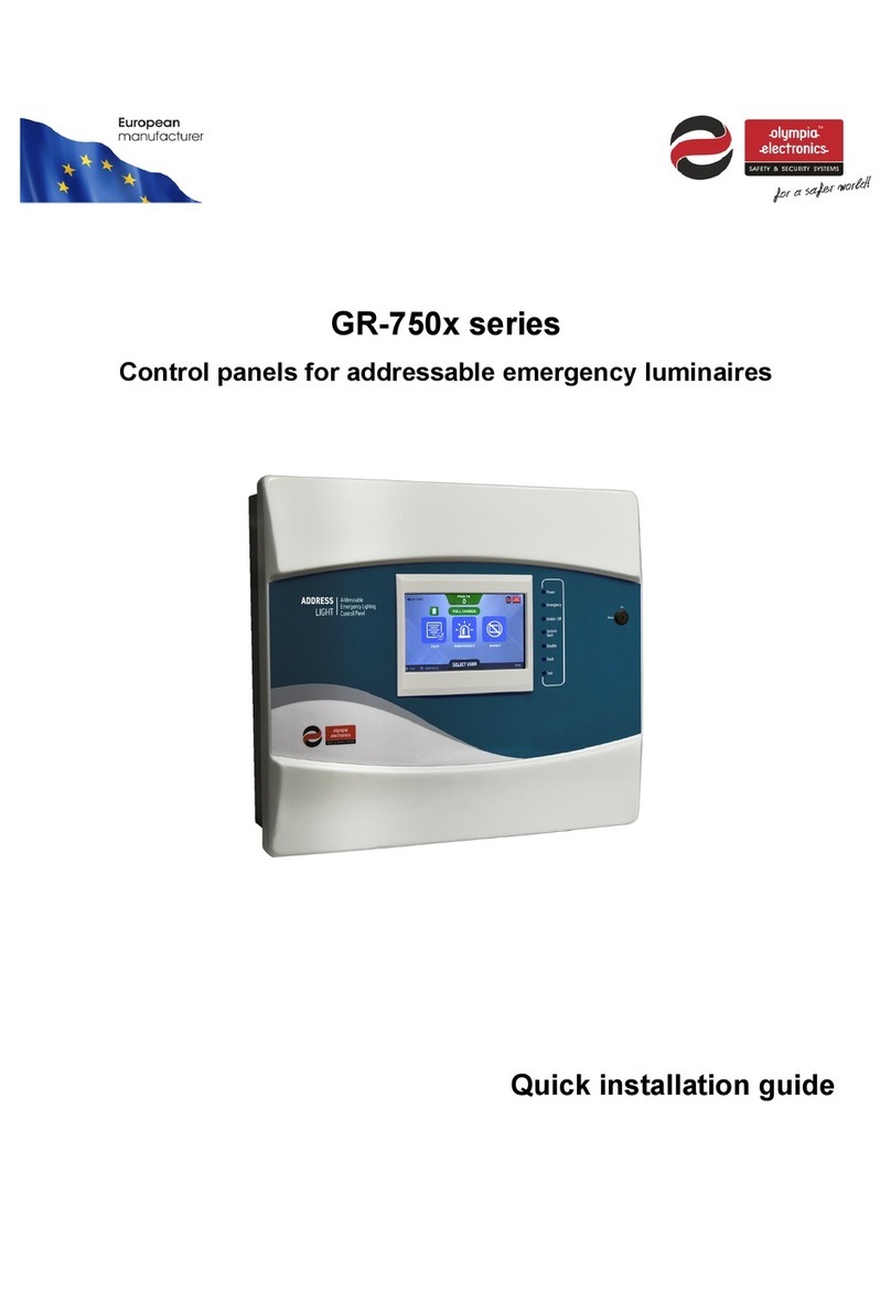
olympia electronics GR-750 Series User manual

GR-750x series
Control panels for addressable emergency luminaires
Specifications
Installation
Configuration
Operation
READ THIS MANUAL PRIOR TO ANY OPERATION

GR-750x series
Control panel for addressable emergency
luminaires
Document number: 923750400_09_007
Date: 3/5/2022
Page: 2 of 71
[2]
Contents
1INTRODUCTION..........................................................................................................................7
1.1 General description............................................................................................................................... 7
1.2 Safety...................................................................................................................................................... 7
1.3 Terms and definitions ........................................................................................................................... 8
1.3.1 Point................................................................................................................................................. 8
1.3.2 Emergency mode/In emergency...................................................................................................... 8
1.3.3 Inhibit mode ..................................................................................................................................... 8
1.4 Technical specification ......................................................................................................................... 9
2SYSTEM DESCRIPTION ..............................................................................................................10
2.1 Control panel fascia ............................................................................................................................ 10
2.1.1 LED indicators ............................................................................................................................... 10
2.1.2 LCD screen.................................................................................................................................... 11
2.1.3 Thermal printer (optional) .............................................................................................................. 11
2.2 Loop circuits ........................................................................................................................................ 11
2.3 Panel relays.......................................................................................................................................... 12
2.4 Inputs.................................................................................................................................................... 12
2.5 Outputs................................................................................................................................................. 12
2.6 Luminaire commands.......................................................................................................................... 13
2.7 Function test ........................................................................................................................................ 13
2.8 Duration test......................................................................................................................................... 13
2.9 Panel network ...................................................................................................................................... 14
2.10 WebUI.................................................................................................................................................... 14
3INSTALLATION..........................................................................................................................15
3.1 Installation/Maintance......................................................................................................................... 15
3.2 Control panel installation.................................................................................................................... 16
3.2.1 Interior of the panel........................................................................................................................ 16
3.2.2 Mounting the panel ........................................................................................................................ 17
3.2.3 Connecting the mains power supply cables (220-240VAC)............................................................ 18
3.2.4 Connecting/Replacing the batteries............................................................................................... 18
3.3 Point wiring .......................................................................................................................................... 19
3.4 Panel network wiring........................................................................................................................... 22

GR-750x series
Control panel for addressable emergency
luminaires
Document number: 923750400_09_007
Date: 3/5/2022
Page: 3 of 71
[3]
3.4.1 Panel network fault examples........................................................................................................ 23
3.5 Relays ................................................................................................................................................... 24
3.6 Inputs.................................................................................................................................................... 25
3.7 Outputs................................................................................................................................................. 26
3.8 Configuration software (PC-7500)...................................................................................................... 27
3.9 Printer paper replace........................................................................................................................... 28
4HOME SCREEN .........................................................................................................................29
4.1 Panel information ................................................................................................................................ 30
4.2 Current fault counter/Fault list........................................................................................................... 30
4.3 Point status .......................................................................................................................................... 31
4.3.1 Charging/Fully charged status....................................................................................................... 31
4.3.2 Emergency status.......................................................................................................................... 31
4.3.3 Function/Duration test status......................................................................................................... 31
4.3.4 Inhibit status................................................................................................................................... 32
4.3.5 Cut off Status................................................................................................................................. 32
4.4 Points in test ........................................................................................................................................ 32
4.5 Points in emergency............................................................................................................................ 32
4.6 Points in inhibit mode ......................................................................................................................... 33
4.7 Select MAIN/TECHNICIAN user menu ............................................................................................... 33
4.8 Duration test postpone indicator....................................................................................................... 33
4.9 Annual check pending indicator........................................................................................................ 34
5TECHNICIAN MENU ..................................................................................................................35
5.1 TEST...................................................................................................................................................... 37
5.1.1 SET FUNCTION TEST.................................................................................................................. 38
5.1.2 SET DURATION TEST.................................................................................................................. 38
5.1.3 START FUNCTION TEST............................................................................................................. 38
5.1.4 START DURATION TEST............................................................................................................. 39
5.1.5 STOP TEST................................................................................................................................... 39
5.1.6 TEST PRINTER............................................................................................................................. 39
5.1.7 TEST INDICATORS ...................................................................................................................... 39
5.2 CHECK.................................................................................................................................................. 40
5.2.1 LOOP............................................................................................................................................. 41
5.2.2 POINTS.......................................................................................................................................... 41
5.2.3 PANEL NETWORK........................................................................................................................ 42
5.2.4 POWER MANAGEMENT .............................................................................................................. 42
5.2.5 INPUTS.......................................................................................................................................... 43

GR-750x series
Control panel for addressable emergency
luminaires
Document number: 923750400_09_007
Date: 3/5/2022
Page: 4 of 71
[4]
5.2.6 OUTPUTS...................................................................................................................................... 43
5.2.7 RELAYS......................................................................................................................................... 43
5.2.8 PRINTER....................................................................................................................................... 44
5.2.9 ANNUAL CHECK DONE ............................................................................................................... 44
5.3 SETUP................................................................................................................................................... 45
5.3.1 CONFIGURE POINT ..................................................................................................................... 46
5.3.2 FIND ALL POINTS......................................................................................................................... 47
5.3.3 CHANGE POINT ADDRESS......................................................................................................... 48
5.3.4 INSTALLED LOOPS...................................................................................................................... 49
5.3.5 OUTPUTS/AUX RELAY ................................................................................................................ 49
5.3.6 INPUTS.......................................................................................................................................... 50
5.3.7 DELETE ALL POINTS................................................................................................................... 50
5.3.8 INHIBIT LOCK ............................................................................................................................... 51
5.3.9 PANEL NETWORK........................................................................................................................ 51
5.4 SETTINGS............................................................................................................................................. 53
5.4.1 LANGUAGE................................................................................................................................... 53
5.4.2 TIME AND DATE........................................................................................................................... 54
5.4.3 ETHERNET/WIFI........................................................................................................................... 54
5.4.4 ANNUAL CHECK WARNING........................................................................................................ 55
5.4.5 PRINTER....................................................................................................................................... 55
5.4.6 CHANGE TECH. CODE................................................................................................................ 55
5.4.7 TECHNICIAN INFORMATION....................................................................................................... 55
5.4.8 REMOTE CONNECTION.............................................................................................................. 56
5.4.9 PC COMMUNICATION (USB)....................................................................................................... 56
5.4.10 FACTORY RESET......................................................................................................................... 57
5.4.11 FIRMWARE UPDATE.................................................................................................................... 57
5.5 CLEAR EVENT LOG............................................................................................................................. 57
5.6 CLEAR FAULTS ................................................................................................................................... 57
6MAIN USER .............................................................................................................................. 58
6.1 CLEAR FAULTS ................................................................................................................................... 60
6.2 CURRENT FAULTS.............................................................................................................................. 60
6.3 EVENT LOG.......................................................................................................................................... 61
6.4 INFORMATION ..................................................................................................................................... 62
6.4.1 ZONES........................................................................................................................................... 63
6.4.2 POINTS.......................................................................................................................................... 64
6.4.3 LOOPS........................................................................................................................................... 65
6.4.4 PANEL RELAYS............................................................................................................................ 65
6.4.5 INPUTS.......................................................................................................................................... 65
6.4.6 OUTPUTS...................................................................................................................................... 66
6.4.7 PANEL NETWORK........................................................................................................................ 66
6.4.8 POWER MANAGEMENT .............................................................................................................. 66
6.4.9 ETHERNET/WIFI........................................................................................................................... 67
6.4.10 ANNUAL CHECK DATE................................................................................................................ 68
6.4.11 SYSTEM INFORMATION.............................................................................................................. 68
6.4.12 TECHNICIAN INFORMATION....................................................................................................... 68

GR-750x series
Control panel for addressable emergency
luminaires
Document number: 923750400_09_007
Date: 3/5/2022
Page: 5 of 71
[5]
6.4.13 LUMINAIRE COMMANDS............................................................................................................. 69
6.5 TEST LED INDICATORS...................................................................................................................... 69
7APPENDIX................................................................................................................................. 70
7.1 List of compatible luminaire models ................................................................................................. 70

GR-750x series
Control panel for addressable emergency
luminaires
Document number: 923750400_09_007
Date: 3/5/2022
Page: 6 of 71
[6]
List of tables
Table 1 - Technical specification table ................................................................................................................ 9
Table 2 –LED indicators ................................................................................................................................... 10
Table 3 –Panel relays....................................................................................................................................... 12
Table 4 –Input triggered actions....................................................................................................................... 12
Table 5 –Panel outputs..................................................................................................................................... 12
Table 6 –Luminaire commands........................................................................................................................ 13
Table 7 –Recommended cable cross section .................................................................................................. 19
Table 8 –Panel network specifications............................................................................................................. 22
Table 9 –Relay terminal connections ............................................................................................................... 24
Table 10 –Relay trigger conditions................................................................................................................... 24
Table 11 –Input triggered actions..................................................................................................................... 25
Table 12 –Input states...................................................................................................................................... 25
Table 13 –Programmable output trigger conditions ......................................................................................... 26
Table 14 –Thermal printer paper specifications ............................................................................................... 28
Table 15 –Technician menu options................................................................................................................. 36
Table 16 –Test menu options........................................................................................................................... 37
Table 17 –Check menu options........................................................................................................................ 40
Table 18 –Setup menu options......................................................................................................................... 45
Table 19 –Panel network menu options........................................................................................................... 51
Table 20 –Settings menu options..................................................................................................................... 53
Table 21 –Main user menu options.................................................................................................................. 59
Table 22 –Information menu options................................................................................................................ 62
Table 23 –Zone menu options.......................................................................................................................... 63
Table 24 –Luminaire commands menu options ............................................................................................... 69
Table 25 –List of compatible luminaire models ................................................................................................ 70

GR-750x series
Control panel for addressable emergency
luminaires
Document number: 923750400_09_007
Date: 3/5/2022
Page: 7 of 71
[7]
1 Introduction
1.1 General description
The GR-750x series of control panels for addressable emergency luminaries consists of four models:
(GR-7501, GR-7502, GR-7503 and GR-7504 with 1, 2, 3 and 4 loop circuits respectively). All share the same
interface, functionality, and indicators. Each of the loop circuits can support up to 250 addressable luminaires.
Two 12V lead acid (Pb) batteries are required per panel, with at least 7Ah capacity each.
All GR-750x models include four programmable inputs, two programmable outputs, two 24VDC voltage
outputs, four relays and an Ethernet/Wi-Fi card. A thermal printer is available as an optional accessory.
Panels of the GR-750x series can be connected to form a network of panels, referenced as “Panel network”.
The maximum number of connected panels cannot exceed 24.
The GR-750x series provides an ideal solution for medium to large scale facilities such as department stores,
hotels, factories.
1.2 Safety
WARNING
To ensure safety and proper use of the device read all accompanying documents
carefully and follow the provided information.
It is recommended that this product is installed, commissioned, and maintained by trained technician
personnel in accordance with:
•The regional regulations for installation and maintenance of electrical appliances in buildings.
•Manufacturer's instructions.
The device main power supply is rated at 220-240Vac/50-60Hz and is a Class I product (the corresponding
terminal contact with the “Protective Earth” marking ( ), inside the device, must be connected to the
building’s ground to ensure proper function and safety).
The mains power supply of the device must be connected to the building’s electrical installation, with its own
separate power line and circuit-breaker rated at 16A, labeled "Emergency lighting system - Do not switch
off".

GR-750x series
Control panel for addressable emergency
luminaires
Document number: 923750400_09_007
Date: 3/5/2022
Page: 8 of 71
[8]
1.3 Terms and definitions
1.3.1 Point
The term “point” refers to any addressable device connected to the panel. For example, an emergency
luminaire.
1.3.2 Emergency mode/In emergency
When the system or a point is referred as being in emergency or emergency mode, it means that its mains
power supply is unavailable, and it is operating on power supplied by its battery.
1.3.3 Inhibit mode
A luminaire set in inhibit mode, will not function as an emergency light. If its mains power supply is
unavailable, it will switch off its lamp (if it is a continuous operation luminaire) or it will not switch on (if it is a
non-continuous operation luminaire). Enabling and disabling the inhibit mode can only be done by the user
(manually).

GR-750x series
Control panel for addressable emergency
luminaires
Document number: 923750400_09_007
Date: 3/5/2022
Page: 9 of 71
[9]
1.4 Technical specification
Table 1 - Technical specification table
GR-750x panel series
Description
GR-7501
GR-7502
GR-7503
GR-7504
Loop circuits
1
2
3
4
400mA max. current per loop, 250 addresses/addressable points per loop
Mains power supply voltage
220-240 Vac, 50/60Hz
Mains maximum current
1.5 A
Maximum consumption
220 VA
Fuse types
AC input: 2A/250V (Slow blow) glass 5x20mm
Controlled inputs*
4 programmable resistance-controlled inputs, open and short circuit
protection, Normal/Active detection with 10kΩ termination resistor
Controlled outputs*
2x 24 VDC (± 3 VDC), 300mA max., Basic isolation
open and short circuit protection, 10kΩ termination resistor
Relays
30Vdc, 5A max (NOT FUSED)
24V voltage outputs*
1x 24VDC (± 3VDC) permanent output, 300mA max., short circuit protection
1x 24VDC (± 3VDC) resettable output, 300mA max., short circuit protection
Battery type
2x Lead-acid batteries (Pb) 12V, 7-15Ah
Battery charger
Stabilized power supply: 27.6V, 900mA
Battery autonomy (7AH)
12-24 hours (depending on the number of connected loop cards, points,
and inputs/outputs)
Battery cut-off voltage
20.5V
Battery discharge current
Nominal: 500mA, 2A max. (while mains power supply is not available)
USB adapter
Micro USB-B 2.0
LAN adapter
10 Mbps Ethernet
Wi-Fi adapter
2.4 GHz, 802.11 b/g/n (802.11n up to 150 Mbps)
Operating temperature
0°C to 40°C
Relative humidity
Up to 95% non-condensing
Case materials
ABS/PC, electrostatic painted iron plate
Ingress protection (case)
IP 30
Dimensions
480mm(L) x 145mm(W) x 408mm(H)
Weight
8kg (without batteries)
Warranty
2 years
* The input/output terminals of the panel are supplied from the 24V power supply unit and have
reinforced insulation from the mains power supply.

GR-750x series
Control panel for addressable emergency
luminaires
Document number: 923750400_09_007
Date: 3/5/2022
Page: 10 of 71
[10]
2 System description
2.1 Control panel fascia
Figure 1
2.1.1 LED indicators
The LEDs indicate when there are certain important statuses active, while more detailed information is
displayed on the screen.
Table 2 –LED indicators
LED LABEL
COLOR
FUNCTION
Power
Green
Indicates panel’s power supply status:
Steady:
Panel powered by mains.
Blinking:
Panel powered by its batteries.
Emergency
Yellow
Indicates that at least one point is in emergency.
Inhibit / Off
Yellow
Indicates that at least one point is in Inhibit mode.
System fault
Yellow
Indicates a system fault.
Disable
Yellow
(Not used.)
Fault
Yellow
Indicates that there is at least one fault.
Test
Yellow
Indicates that at least one point is in test.

GR-750x series
Control panel for addressable emergency
luminaires
Document number: 923750400_09_007
Date: 3/5/2022
Page: 11 of 71
[11]
2.1.2 LCD screen
The panel is equipped with a 7” TFT LCD touch screen display which can be used to control the panel and
provide information to the user.
2.1.3 Thermal printer (optional)
The thermal printer is an optional accessory it is not included in the panel by default. It can be
enabled/disabled from the settings menu as required. When the printer is enabled, every event that is
recorded is printed as well.
2.2 Loop circuits
All models of the GR-750X series use the same loop boards, they only differ in number. The loop output
connection terminals come pre-installed with a short-circuit adapter (it links +L to +LF and –Lto –LF
terminals, to form a closed loop circuit).
A loop circuit can operate with up to 250 addresses and a maximum of 250 points connected to it.
Figure 2

GR-750x series
Control panel for addressable emergency
luminaires
Document number: 923750400_09_007
Date: 3/5/2022
Page: 12 of 71
[12]
2.3 Panel relays
Panel has four relays located on the power management board marked AUX, FAULT, SUPPLY and OPER.
The behavior of the operation (OPER), supply (SUPPLY) and fault (FAULT) relays is predefined and cannot
change. All relays are rated 30Vdc, 5A max. External fuses must be added based on the rated current of the
connected circuit.
Operation of each relay is described at the table below.
Table 3 –Panel relays
RELAY
DESCRIPTION
Operation
Relay state depends on system operation.
Supply
Relay state depends on the status of mains power supply.
Fault
Relay state changes if there is one or more faults.
Auxiliary
Operation of this relay is user configurable.
2.4 Inputs
The panel has four programmable inputs on the power management board marked as IN1, IN2, IN3 and IN4
on the PCB. Each input can be programmed to perform a specific action on all zones or a certain zone.
Activating an input can trigger one of these actions:
Table 4 –Input triggered actions
TRIGGERED ACTION
DESCRIPTION
FUNCTION TEST
Starts a function test on the points of the selected zone.
INHIBIT
Sets all points of the selected zone in inhibit mode.
RESET PANEL FAULTS
Resets the active faults on the panel.
2.5 Outputs
The panel has four outputs on the power management board marked as 24VP, 24VM, OUT1 and OUT2 on
the PCB. Two of them are voltage outputs (24VP and 24VM) and the other two are programmable outputs
(OUT1 and OUT2).
Table 5 –Panel outputs
NAME
VOLTAGE
RATED
CURRENT
LINE
MONITORING
DESCRIPTION
24VP
24Vdc
300mA
Short circuit
Output is active while the panel is operating.
24VM
24Vdc
300mA
Short circuit
Output is active while panel is operating.
After power-on the output is inactive for 10sec.
OUT1
24Vdc ±3V
300mA
Open/Short circuit
Operation of this output is user configurable.
OUT2
24Vdc ±3V
300mA
Open/Short circuit
Operation of this output is user configurable.

GR-750x series
Control panel for addressable emergency
luminaires
Document number: 923750400_09_007
Date: 3/5/2022
Page: 13 of 71
[13]
2.6 Luminaire commands
A list of the commands the panel can sent to the luminaires can be found below, along with the description of
each command.
Table 6 –Luminaire commands
COMMAND
DESCRIPTION
FUNCTION TEST
Starts a function (operational) test on the specified luminaires.
DURATION TEST
Starts a duration (autonomy) test on the specified luminaires.
STOP TEST
Stops all running tests on the specified luminaires.
IDENTIFY
The LED indicators of the specified luminaire start blinking so it
can be visually identified.
INHIBIT MODE
Sets the specified luminaires to inhibit mode.
CLEAR COMMANDS
Resets all commands/modes of the specified luminaires.
RESET FAULTS
Reset the faults of the specified luminaires.
2.7 Function test
Function test procedure initiates a self-test (operational test) procedure of the luminaires connected to the
panel, to verify their proper operation. No specific equipment is required and can be manually performed at
any time or scheduled at specific days of the week at a certain time. During the test, a LED indicator flashes
on the luminaire indicating the ongoing operation. For more information about the LED indicators of the
luminaire, refer to its manual.
Upon completion of the test, if a problem is detected by the luminaires, the panel will be notified, the
corresponding fault will appear in the fault list with detailed information.
2.8 Duration test
Duration test procedure initiates a self-test (autonomy test) procedure of the luminaires connected to the
panel, to evaluate the endurance of their batteries. No specific equipment is required and can be manually
performed at any time or be scheduled up to two times per year. During the test, a LED indicator flashes on
the luminaire indicating the ongoing operation. For more information about the LED indicators of the luminaire,
refer to its manual.
Upon completion of the test, if a problem is detected by the luminaire, the panel will be notified, the
corresponding fault will appear in the fault list with detailed information.

GR-750x series
Control panel for addressable emergency
luminaires
Document number: 923750400_09_007
Date: 3/5/2022
Page: 14 of 71
[14]
2.9 Panel network
The panels of the GR-750x series can be connected and form a network of panels, referenced as “Panel
network”, using the NET-L and NET-R terminals on the power management board. The maximum number of
connected panels cannot exceed 24. There is the option to enable/disable the networking capability of each
panel as required.
When two or more panels are connected, there is the option to form a trusted panel network. Panels in the
same trusted network will synchronize events (automatic process), some settings and point commands are
applicable to all of them simultaneously.
Each panel has its own name, ID, and MAC address. For panel to form a trusted group, all members must
have unique ID. This can be done automatically or be configured manually, depending on what is required
(refer to 5.3.9 PANEL NETWORK for group formation).
The panel network line is monitored for open or closed ring topology (refer to 3.4 Panel network wiring). In the
case of system failure of the panel network controller (MCU), the board will internally connect the NET-L with
NET-R signals, to preserve the communication between the other panels. This is the reason why a closed ring
topology is strongly recommended.
Figure 3
2.10 WebUI
The Ethernet/Wi-Fi card provides a website for remote monitoring and configuration of the panel. It is
accessible from any device with browser support if it is connected to the same network as the Ethernet/Wi-Fi
card of the panel. Two different access levels are available (User and Technician), each with a separate
configurable password (see 5.4.8 REMOTE CONNECTION screen for more details).
The html link (URL) for the website is the IP address of the Ethernet/Wi-Fi card in the local network (this can
be found in the 6.4.9 ETHERNET/WIFI screen and configured from the 5.4.3 ETHERNET/WIFI screen).

GR-750x series
Control panel for addressable emergency
luminaires
Document number: 923750400_09_007
Date: 3/5/2022
Page: 15 of 71
[15]
3 INSTALLATION
3.1 Installation/Maintance
WARNING
All installation operations must be done while the panel is disconnected from mains
power supply and batteries. Only trained personnel should carry out operations inside the
panel and only after taking all the precautionary measures.
Prior to installing/maintaining the panel, read the manual and have knowledge of the system capabilities,
functionality, and design to ensure proper operation of system.
Do not connect or disconnect system components while mains power supply or batteries are connected.
Prior to any operation inside the enclosure of the panel, ESD prevention measures should be taken.
Figure 4

GR-750x series
Control panel for addressable emergency
luminaires
Document number: 923750400_09_007
Date: 3/5/2022
Page: 16 of 71
[16]
3.2 Control panel installation
3.2.1 Interior of the panel
To access the interior of the panel, first unlock the key lock on the front of the panel with the key included in
the panel’s package.
Figure 5
On the inner side of the panel’s door is mounted the TFT-LCD touch screen display and the DOOR board
(Figure 5). Connected to the DOOR board are the LCD CPU board, the ETHERNET/WIFI board and the
PRINTER board (if the optional printer accessory is installed).

GR-750x series
Control panel for addressable emergency
luminaires
Document number: 923750400_09_007
Date: 3/5/2022
Page: 17 of 71
[17]
Inside the main body of the metal housing (Figure 6) are located the power supply unit (left), the power
management board (MAIN board), the loop boards (center), the battery area for the two batteries (bottom),
the earth bar terminal (left), the panel mounting holes and the cable openings.
Figure 6
3.2.2 Mounting the panel
The panel mounting area must be clean, dry, and free of collisions and vibrations. The panel must be
permanently installed on a fixed position and indoors only. In Figure 6, the interior mounting holes of the panel
are marked. Use all three mounting holes with the included wall mounting accessories of the package for
proper installation (plugs and screws).
The panel should be placed at least 1m above floor level, 1m bellow roof level and at a minimum distance of
30cm from other electronic devices. No other lines should cross the wall behind the panel except the panels
own power supply. The panel should be placed in a visible and accessible area to the building’s stuff, fire, and
lighting safety personnel.

GR-750x series
Control panel for addressable emergency
luminaires
Document number: 923750400_09_007
Date: 3/5/2022
Page: 18 of 71
[18]
3.2.3 Connecting the mains power supply cables (220-240VAC)
IMPORTANT
1. Any installation, repair or electrical equipment maintenance operation must be executed
with both mains power supply and batteries disconnected.
2. All mains power cables must be connected before connecting the batteries and powering
up the system.
3. The mains power fuse is located on the power management board and is rated
T2A/250V (slow blow).
4. The battery protection fuse is self-resettable, rated 900mA and is soldered on the power
management.
The power supply cable must be a 3−core double insulated wire that meets the voltage and current
requirements of the panel (Table 1 - Technical specification table).The ground terminal (marked with on the
power management board) must be connected to the installation’s ground (protective earth) to ensure proper
and safe operation of the system.
Figure 7
3.2.4 Connecting/Replacing the batteries
The interior of the control panel has space suitable to hold two 12V lead-acid batteries (Pb) with nominal
capacity of 7Ah, 9Ah, 12Ah or 15Ah. Both batteries must be the same model, type and have the same
nominal capacity.
The two batteries must be connected in series. Three wires are provided to connect them, two of them are
pre-installed on the power management board’s battery terminals. The red wire must be connected to the
positive terminal (+) of the first battery. The black wire must be connected to the negative terminal (-) of the
second battery. A jumper cable is included in the accessories bag, to connect the two other terminals
(negative terminal (-) of the first battery to the positive terminal (+) of the second battery), like it is shown in the
figure below:
Figure 8
In case of battery replacement, both batteries must be changed with two new identical batteries. Do not
discard the old batteries in common waste bins. The batteries must only be disposed of in accordance with
the WEEE directive.

GR-750x series
Control panel for addressable emergency
luminaires
Document number: 923750400_09_007
Date: 3/5/2022
Page: 19 of 71
[19]
3.3 Point wiring
Use a cable that meets these specifications, to connect the loop board with the points:
1. Two−core shielded twisted pair cable. If the cable is unshielded, the communication between the loop
and the points is susceptible to electromagnetic interferences.
2. No more than 2 cores.
3. Low resistance, less than 25 Ohm/km. The total impedance of each core of the cable should not be
more than 20 Ohm.
4. Wire cross section should be between 0,7mm² and 2,5mm².
5. Low capacitance, less than 200pF/m. The total capacitance of a single cable should not exceed
800nF.
Table 7 –Recommended cable cross section
Loop cable length
200m
500m
1000m
1500m
2000m
Point number
50
0.75 mm2
1 mm2
1 mm2
1.5 mm2
2.5 mm2
100
1 mm2
1 mm2
1.5 mm2
1.5 mm2
2.5 mm2
150
1.5 mm2
1.5 mm2
2.5 mm2
2.5 mm2
2.5 mm2
200
1.5 mm2
1.5 mm2
2.5 mm2
2.5 mm2
2.5 mm2
250
1.5 mm2
1.5 mm2
2.5 mm2
2.5 mm2
2.5 mm2
We recommend LiYCY (TP) type cables with cross section from 0.75mm2to 1.5mm2 or YSLYCY-JZ with cross
section from 1mm2to 2.5mm2, depending on the number of connected points, topology of the installation and
cable length.
WARNING
The maximum length of a single loop cable should not exceed 2000m. The maximum
connected points per loop are 250.
The upper and lower cable openings of the metallic enclosure of the panel can be used to drive the cables
through. The rubber plugs should not be removed from the openings, so the ingress protection IP30 remains
unchanged. Instead pierce a hole on the rubber plug, big enough to barely fit the cable and drive the cable
through it. To connect one or more points to the loop output terminals, remove the short-circuit adapter.
IMPORTANT
1. The cable’s shield must be reconnected in every cut throughout the length of the loop
and must be connected to the earth bar of the panel.
2. The positive and negative polarity must be maintained throughout the length of the
loop.
3. All points must be connected in parallel with the output.
4. If the number of installed points in on a loop circuit exceeds 50, or if the length of its
cable exceeds 500m, then a closed loop connection topology is always recommended,
to minimize communication issues.
Other manuals for GR-750 Series
1
This manual suits for next models
4
Table of contents
Other olympia electronics Control Panel manuals

olympia electronics
olympia electronics BS-316 User manual

olympia electronics
olympia electronics BS-627 User manual

olympia electronics
olympia electronics BS-1632 User manual

olympia electronics
olympia electronics GR-6500 User manual

olympia electronics
olympia electronics BS-746 User manual

olympia electronics
olympia electronics GR-750 Series User manual

olympia electronics
olympia electronics GR-6500 User manual