Page 2 from 3
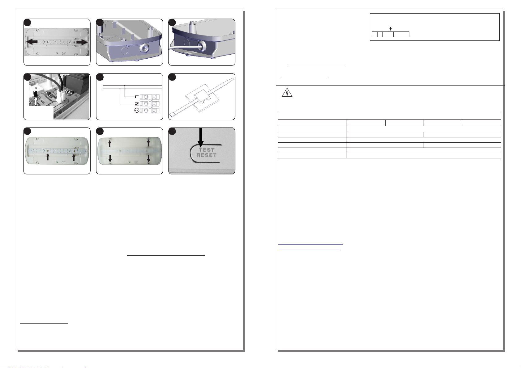
Unfasten the mounting screws (step 8) and remove the diffusor. When the luminaire is supplied
by the mains, press on the marking for TEST as shown on the picture below. Mount the diffusor
by using the 4 removed screws.
Step 1. Remove the diffusor. Place a flat blade screwdriver and pull the reflector gently (with
opposite orientation in relation to the plastic base).
NOTE!! If you don’t need the yellow leds to light in normal operation, then remove the led
jumper.
Step 4. Place the battery’s connector to the corresponding connector on the PCB.
Battery replacement
4. Replace the removed parts (previous steps 1,2).
Step 5. Connect the mains as shown on figure (connect the ground wire if required).
Step 6. Install the included tie (if needed) to fasten securely the power cables.
Step 9. Manual Test.
NOTE!! After finishing the installation you must power the luminaire at least for 24 hours
for battery charging to perform the nominal autonomy.
3. Remove the old battery and place a new on of the same type and characteristics.
Step 7. Refit the reflector and fasten the two small screws (included).
Step 8. Finally place the diffusor by using the 4 included screws (tightening torque 1.2Nm).
1. Unfasten the 4 retaining screws (step 8 of the installation instructions) and remove the diffusor.
Step 3. Use a small flat bladed screwdriver to open Install the second rubber gasket into the hole.
a hole in the rubber gasket and pass through the mains cable. Always use in any case round
mains cable, with a diameter of 6-9mm (H05RN-F type 2x1mm² or any other type, at least
equal to it’s mechanical and electrical properties).
Step 2. Install the included rubber gasket into the unused hole. Install the plastic base with the
included mounting screws and plugs.
ATTENTION!! The cable and the rubber gaskets must not be deformed in any way. (This
requirement is important to ensure the tightness isolation IP65).
2. Unfasten the 2 retaining screws step 7 of the installation instructions and remove the reflector.
INSTALLATION INSTRUCTIONS
923936010_09_003
LED MODULE CHARACTERISTICS
Olympia Electronics S.A
45 °C max. across the board
Cable connection between main pcb and led module
8.7-10.8VDC
1W2W
1605163/15L 1605163/30L
GR-935/15L
GR-936/15L
GR-935/30L
GR-936/30L
Manufacturer
Model Number
Voltage Range
Connections
Nominal Power
Temperature (tc)
NOTE: LED= Light Emitting Diode
LABELING EXPLANATION:
X: Self contained
A: Including test device
G: Internally illuminated
0: Non Maintained (*)
*90: 90min duration
Note!! The installer should fill in, on the specification label,
the letter G if the luminaire is used as a safety sign.
WARRANTY
Olympia Electronics guarantees the quality, condition and operation of the goods. The period of
warranty is specified in the official catalogue of Olympia Electronics and also in the technical leaflet,
which accompanies each product. This warranty ceases to exist if the buyer does not follow the
technical instructions included in official documents given by Olympia Electronics or if the buyer
modifies the goods provided or has any repairs or re-setting done by a third party, unless Olympia
Electronics has fully agreed to them in writing. Products that have been damaged can be returned to
the premises of our company for repair or replacement, as long as the warranty period is valid.
Olympia Electronics reserves the right to repair or to replace the returned goods and to or not charge
the buyer depending on the reason of defection. Olympia Electronics reserves the right to charge or
not the buyer the transportation cost.
HEAD OFFICE
www.olympia-electronics.com
P.C. 60300 P.O. Box 06 Eginio Pierias Greece
72nd km. O.N.R. Thessaloniki-Katerini
*
X09 0A G
The light source contained in this luminaire shall only be replaced by the manufacturer, or his
agent, or a similar qualified person.
NOTE! The light source is non-user replaceable.
Page 3 from 3 923936010_09_003
(*) Non Maintained operation: The luminaire lights its illumination source, only in power supply’s
failure.
Maintained operation: The luminaire lights its illumination source, when it is powered by the mains
power supply or not.
1
78 98
5 6
2 3
4


