olympia electronics MLD Series User manual

MAINTAINED/NON-MAINTAINED (OPTIONAL) ILLUMINATION SIGNS WITH WHITE LEDs
GENERAL
These sign illumination luminaires use a new
technology, friendly to the environment, with high
illuminated L.E.D.s. L.E.D. technology has very low
power consumption.
The edge illumination sign is used as a maintained
emergency lighting with indications symbols.
In this type of marking panels, the PVC overlay is
mounted on the marking panel with 4 plastic screws,
and it can be changed by change the PVC overlay in
accordance with the desired result.
Each model combines modern, aesthetics, together
with functionality. The exit illumination signs are used
in every public area where clear direction and good
appearance are important.
NON MAINTAINED OPERATION
By default the illumination sign operates as maintained.
The device has a possibility to operate as non
maintained. To change the maintained to non-
maintained operation follow the relative instructions on
page 6.
All models must be permanently connected to the
mains power supply as shown on page 2.
The legend is screened on to a clear acrylic sheet
which has the marking on the marking panel with the
light that comes from the top of the luminaire and
diffracts, giving light to the marking panel.
The luminaire has an indication (CHARGE) for the
charging of the battery and a (TEST) button to TEST
the emergency circuit and the LEDs for good operation
only when the luminaire is powered by the mains power
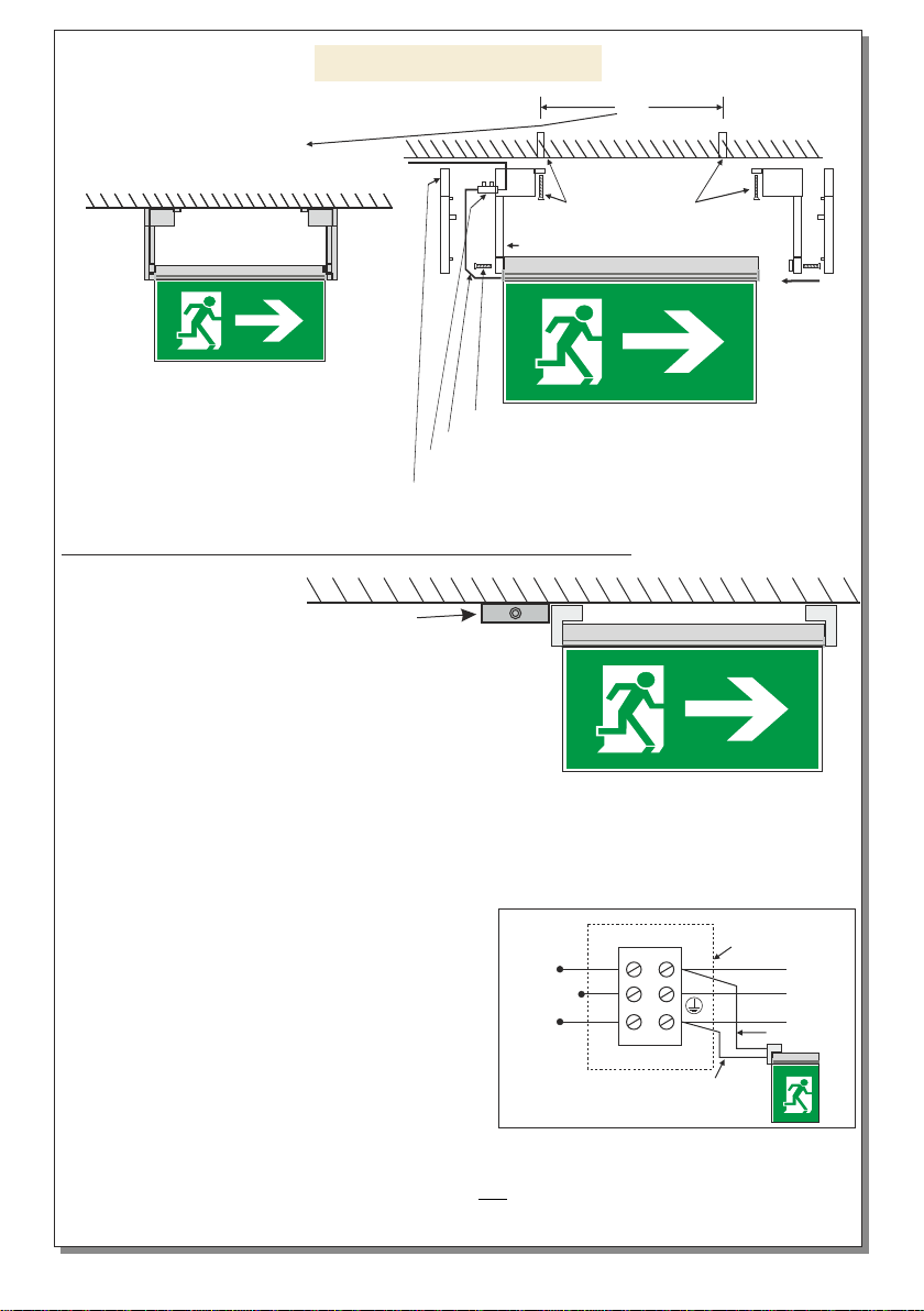
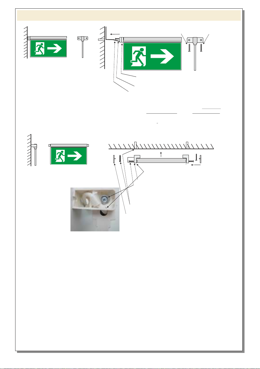
supply. The unit must be mounted in a clearly visible
area and can either be hung on a ceiling or mounted on
a wall depending on the requirements of the
installation. The package includes all the required
materials for mounting on the wall or on the ceiling.
The pages 2,3 and 4 show us the mounting
methods.
WARNING !!
1. Read carefully this instruction manual.
2. Before service interrupt the mains power supply.
3. The device must be connected to the mains power
supply through a fuse dependent by the total amount of
the line’s power load.
4. It is suggested to check every month the indication
LED for battery charging, and by pushing briefly the
TEST button to check the emergency circuit. The sign
should light for a few seconds powered by the battery
and then, will turn to normal operation
5. full
by disconnecting the mains power supply
Count the autonomous duration of the luminaire and in
case of no correspondence to stated emergency
duration replace the battery The replacement of the
battery must be done using parts of the same type, by
the manufacturer or by a competent person.
7Replaced batteries must not be thrown into
trash bins. They must be returned to special
battery disposal points.
Do not incinerate.
NOTE: LED= Light Emitting Diode
LABELING EXPLANATION:
X: Self contained 1: Maintained (*)
A: Including test device G: Internally illuminated
safety sign. 180: 3 hour duration
(*) Maintained operation: The luminaire lights its
illumination source, when it is powered by the mains
power supply or not.
Non-Maintained operation: The luminaire lights its
illumination source, only in power supply’s failure.
. In the opposite
condition contact the installer.
Every six months, a duration check should be
carried out .
.
6. In case of inactive use for a period greater than 2
months, disconnect the battery by pulling out the
battery’s connector.
.
922504417_09_032
Page 1 from 6
MLD-34D/w MLD-44D/w
MLD-28D/w
TECHNICAL CHARACTERISTICS
FOR LED MODULE SPECS. see page 6
Operation temperature range
Relative humidity
External panel's dimensions
External dimensions (LxWxH)
Typical weight
Guarantee
Mains voltage
Maximum power consumption
Battery (Ni-Cd)
Recharging time
Battery protection
Minimum emergency duration
Degrees of cover protection
Class of cover protection
Produced in accordance with
Light source intensity (Mains / Emerg)
220-240V AC/50-60Hz
3h
24h
Overcharging and deep discharging protection
IP40
class II
3.6V/1Ah
105lm/85lm
85lm/85lm
3W / 8VA3W / 7.5VA
5-40 C
ο
up to 95%
280x100mm
305x25x155mm
3 years (1 year for the battery)
340x170mm
365x25x225mm 440x220mm
465x25x275mm
EN 60598-1, EN 60598-2-22, ΕΝ 55015, ΕΝ 61547, ΕΝ 61000-3-2, ΕΝ 61000-3-3
520gr. 850gr. 1310gr.
Thank you for your trust in our products. Olympia Electronics - European manufacturer.
Construction material ABS/PC, Acrylic plate, PVC

Page 2 from 6 922504417_09_032
Preparation procedure
for ceiling mounting Connection of the included terminal block
LL
NN230V AC
BROWN
BLUE
Attention!!! Interrupt the mains power supply.
Mounting methods
2. Place the plastic part for mounting the sign.
1. Open the pre-etched knock out and pass
the cable through.
3. Place the cable holding accessory and mount it by
tightening the screw with the included grommet.
4. Connect the wires to the included terminal block and place it
in the plastic mounting part.
5. Follow the procedure bellow (figure 1).
Hanging installation on
suspended ceilings using the
special mounting brackets
contained in the package.
MLD-28 S: 29.5cm
MLD-34 S: 35.7cm
MLD-44 S: 45.7cm
2
S1
4
3
Hanging installation on
suspended ceilings using the
special mounting brackets Figure 1
1. Attention!!! Choose the installation area to insure that the mounting surface is appropriate for the
installation of the illumination sign.
2. Measure the space S according to the illumination sign’s type and drill the appropriate holes in the
ceiling for the installation of the included mounting plugs Nr 6.
3. Place the mounting plugs Nr 6 and mount the sign by tightening the included mounting screws.
4. Refit the plastic cover on each side.
5. Power the illumination sign and check the illumination sign’s operation.
Recessed mounted installation
on suspended ceilings using
the base type Α-1018/PL,
Α-1020/PL, Α-1021.
A-1018/PL
A-1021
440
75
Ø6
Suspended ceiling mounting bases
Ceiling mounting
A-1020/PL

Page 3 from 6 922504417_09_032
4. Connect the wires to the included terminal block and place it
in the plastic mounting part.
1. Place the plastic mounting part
5. Place the mounting accessories in the
wall and tighten the mounting screw.
2. Tighten the screw.
3. Pass the cable in the canal.
6. Place the plastic cover.
S2
MLD-28 S: 22cm
MLD-34 28S: cm
MLD-44 37 5S: . cm
Use a certified electrical box 250V AC (IP40) to
perform the electrical connection, with minimum
internal space 35x35x25mm to install the 3 pole
terminal block. In this box install a certified 3 pole
terminal block 250V AC/16A 2,5mm² providing
terminals to connect the live wire L, the neutral N
and the ground GND. To this terminal block is
connected the power cable with a cross section of
1,5mm². Install the electrical box in an appropriate
area in the ceiling. Install securely the 3 pole
terminal block and perform the connection according to figure 3.
The electrical box and the 3 pole terminal block not included. Installation may require
advice from a qualified person.
Electrical box
(Not included)
Figure 2
ELECTRICAL BOX INSTALLATION
1. Attention!!! Interrupt the mains power supply.
2.Perform the preparation procedure for ceiling mounting on
page 2 and exclude step 4.
3. Perform the procedure for ceiling mounting figure 1.
4. For the installation of the electrical box you may need to
open holes in the ceiling and at it’s cable entrances, for the
entrance of the power and illumination sign’s cables. Install the electrical box next to the sign so as
to cover the cable (figure 2).
5. After mounted the electrical box open the cover and perform the electrical connection according to
Figure 3. After the connection close the cover of the box.
6. Power the illumination sign and check the illumination sign’s operation.
OPTIONAL !!
When a triple core cable must be used, then follow the figures 2,3 bellow.
Ceiling mounting
220-240V AC/50-60Hz
BLUE
L
GND
NBROWN
Electrical
box
Figure 3

Page 4 from 6 922504417_09_032
2. Place the plastic part
1. Open the pre-etched knock out and pass the
cable through.
3. Place the cable holding accessory and mount it by
tightening the screw with the included grommet.
5. Place the mounting accessories in the wall
and tighten the mounting screw figure 1 step 3.
6. Place the plastic cover.
Wall in bottom view
Wall mounted installation
using the special mounting
brackets contained in the
package.
Flag mounted installation on
a wall using the special
mounting bracket contained
in the package. 2. Place the single mounting plastic part
3. Tighten the mounting screw.
1. Open the pre-etched knock out and pass the cable
through.
5. Place the mounting accessories in the wall
and screw the mounting screws
Wall mounting
4.
place it in the plastic mounting part.
Connect the wires to the included terminal block and
6. After finishing the installation, the cable
suitable cable detention bracket (not included) to ensure
immobilization of the cable at a distance of no more than
5cm from the luminaire’s cable entry.
secure with a

Page 5 from 6
10 11
46
9
8
1 Remove the plastic cover from each side. (figure 1, step 4).
2 Unfasten the mounting screws to unmount the illumination sign (figure 1, step 2).
3 You have to disconnect the power supply wires of the sign from the terminal block.
4 Unfasten the mounting screw of the bracket and remove it.
5 Unfasten the mounting screw (with the cable holding accessory) of the bracket and remove the
bracket.
6 Unfasten the screw without moving the marking panel.
7 Remove the marking panel.
8 Slide out the led strip with a flat blade screwdriver.
9 Pull carefully the led strip by holding it from the two sides as shown in picture.
10 Remove the used battery and place a new one with the same type Α-939/ΗΤ with same cables
and connector.
11 Push carefully the led strip by holding it from the two sides as shown in picture.
12 Push the led strip to face the edge of the plastic cover.
ATTENTION !!! Don’t apply force to the test button.
13 Refit the removed parts in steps 7,6,5 and 4.
WARNING!! Use a maximum torque of 0,25Νmto tighten the screw (step 6) and a maximum
torque of 0,6Νmto tighten the screws (step 4,5).
14 Mount the illumination sign with the mounting screws (figure 1, step 4).
15 Connect the power supply wires of the sign to the terminal block (step 3). Refit the plastic
cover (figure 1, step 5) and power the illumination sign.
Before service interrupt the mains power supply.
5
Battery replacement process
922504417_09_032
The light source contained in this luminaire shall only be replaced by the manufacturer, or his
agent, or a similar qualified person.
NOTE! The light source is non-user replaceable.
NOTE!! After finishing the installation you must power the luminaire at least for 24 hours for
battery charging to perform the nominal autonomy.
12

Page 6from 6
MAINTAINED TO NON MAINTAINED SELECTION CAPABILITY
Power on the device and press continuously the TEST button for 5 seconds, until the led strip
turns off. Release the button and after a short emergency test, the device operates as
non maintained. If you want to restore the previous condition (maintained operation), press
continuously the TEST button for 5 seconds, until the led strip lights. Release the button and
after a short emergency test, the device operates as maintained illumination sign.
Troubleshooting
Trouble
1. The illumination sign does not light when the TEST
button is pressed.
2. During the 6month autonomous check, t
illumination sign does not light or has less autonomy
than the nominal.
he
3.
operation.
The illumination sign does not light in normal
4.
failure
The illumination sign does not light during a mains
.
The battery has lost it’s energy
Wait at least for 1 hour for the battery to be charged.
Attach the battery’s connector to the appropriate
connector on the P.C.B.
The battery is inappropriate
Τhe battery must be replaced.
The battery is not connected
The battery has lost it’s energy
Wait at least for 24 hours for the battery to be fully
charged.
The battery is inappropriate
Τhe battery must be replaced.
The illumination sign is adjusted to operate as
non-maintained
Choose (if you must) to turn the operation to
maintained, according to relative paragraph in
page 6.
The battery has lost it’s energy
Wait at least for 24 hours for the battery to be fully
charged.
The battery is not connected
Attach the battery’s connector to the appropriate
connector on the P.C.B.
The battery is inappropriate
Τhe battery must be replaced.
Solution
922504417_09_032
MLD-34D/w MLD-44D/w
MLD-28D/w
LED MODULE CHARACTERISTICS
Manufacturer
Model Number
Voltage Range
Connections
Nominal Power
Temperature (tc)
Olympia Electronics S.A.
45 °C max. across the board
fixed connection between main pcb and led module
8.5-10.5V DC
18021611702161 1902161
800mW 980mW 980mW
WARRANTY
OlympiaElectronicsguaranteesthequality,conditionandoperationofthegoods.Theperiodofwarranty
is specified in the official catalogue of Olympia Electronics and also in the technical leaflet, which
accompanies each product. This warranty ceases to exist if the buyer does not follow the technical
instructionsincludedinofficialdocumentsgivenbyOlympiaElectronicsorifthebuyermodifiesthegoods
provided or has any repairs or re-setting done by a third party, unless Olympia Electronics has fully
agreed to them in writing. Products that have been damaged can be returned to the premises of our
companyforrepairorreplacement,aslongasthewarrantyperiodisvalid.
Olympia Electronics reserves the right to repair or to replace the returned goods and to or not charge the
buyer depending on the reason of defection. Olympia Electronics reserves the right to charge or not the
buyerthetransportationcost.
HEADOFFICE
72ndkm.O.N.R.Thessaloniki-Katerini
P.C.60300P.O.Box06ΕginioPieriasGreece
www.olympia-electronics.gr
This manual suits for next models
3
Table of contents
Other olympia electronics Safety Equipment manuals
Popular Safety Equipment manuals by other brands

EUCHNER
EUCHNER CES-AZ-AES Series operating instructions

SIP
SIP PAPR WR1000 user manual

FireFlex Systems Inc.
FireFlex Systems Inc. TOTALPAC 3 FIRECYCLE III Owner's operation and maintenance manual

Westward
Westward 2MZU5 Operating instructions and parts manual

Pelsue
Pelsue DBF-43A product manual

Newtec
Newtec NT 02 EN361 General Instructions for Use