manuals.online logo
Brands
  1. Home
  2. •
  3. Brands
  4. •
  5. Olympus
  6. •
  7. Microscope
  8. •
  9. Olympus K Operating instructions

Olympus K Operating instructions

OLYMPUS
STUDENT
MICROSCOPES
MODELK
&
KC
REPAIR
MANUAL
OLYMPUS
TO
OLYMPUS
MICROSCOPE
SERVICING
PERSONNEL
As
is
often
the
case
with
almost
all
of
compound
microscopes
that
unless
they
are
kept
in
good
maintenance
and
storage
after
long
years
of
use,
grease
slums
have
been
dried
up
or
air-borne
dust
has
been
deposited
on
grease
so
much
as
to
interfere
with
smooth
operations
of
various
components,
causing,
for
instance,
excessive
stiffness
or
looseness
in
the
coarse
and
fine
adjustments,
etc;
Microscopes
in
trouble
as
mentioned
above
need
disassembly
and
lubrication.
As
a
helpful
aid
for
such
a
servicing
purpose,
this
manual
has
been
written
in
the
hope
that
you
will
make
the
best
use
of
it
and
give
us
any
comment
on
it.
Requisites
for
repairs:
1.
First
of
all,
ascertain
what
parts
of
the
microscope
the
user
or
owner
of
which
wishes
you
to
repair.
2.
Never
fail
to
check
the
entire
function
of
the
microscope
before
you
commence
its
repair.
a)
Find
out
what
parts
are
defective
and
how
much
they
are
damaged.
b)
Prior
to
repair,
think
of
the
best
possible
order
of
disassembling
the
defective
parts
in
a most
efficient
way.
3.
After
completing
the
repair,
check
the
functions
of
not
only
the
re-
assembled
parts
but
also
the
entire
microscope
to
make
sure
no
defect
should
be
left
unremedied.
4.
Be
careful
not
to
deform
repair
parts
during
the
assembly;
make
it
practice
to
use
tools
and
jigs
specified
for
purpose.
5.
Make
repairs
promptly
and
accurately.
- 1 -
CONTENTS
1.
REPAIR
TOOLS
AND
GREASE
1-1
Regular
Tools
1-2
Special
Tools
1-3
Grease.
2. Exploded Drawings.
3.
Disassembly
of
K,
KC
3-1
Disassembly
of
Focusing
Mechanism
3-2
Assembly
of
Focusing
Mechanism. .
.
3-3
Adjustment
of
Stage
Surface
at
Right
Angles
with
the
Optical
Axis
. .
3-4
Disassembly
of
Observation
Tube .
3-5 Assembly and
Adjustment
of
Observation
Tube .
3-6
Centration
of
Condenser
Holder.
3-7
Adjustment
of
Condenser
Height.
3-8
Disassembly
of
Stage
K-CS-5
..
- 2 -
. . .
3
3
3
4
6
15
24·
26
27
29
30
31
1.
REPAIR
TOOLS
AND
GREASE
1-1
Regular
Tools
OT
0011
OT
0015
OT
0017
OT
0018
OT
0021
OT
0022
OT
0023
OT
0027
OT
0035
OT
0079
OT
0216
Set
of
screwdrivers
(6
pes.)
Phillips
screwdriver
(medium
size)
Screwdriver
(small
size)
Screwdriver
(large
size)
Adjustable
spanner
(round
tip)
Adjustable
spanner
(flat
tip)
Handle
of
small
size
Phillips
screwdriver,
using
OT
0027
Phillips
screwdriver
tip,
using
OT
0023
Tweezers
Pliers
(size:
160mrn)
Set
of
Allen
wrenches (8
pes.)
1-2
Special
Tools
KKAA0044
KKAA0055
KKAA0075
KKAA0077A
KKAA2337
KKAA2891
KKAE0275
KC2016
KC2022
C-1
KN0004
SKN0004
SKN0005
1-3
Grease
E-1
E-4
E-7
Pin
face
wrench
for
part
No.
AA
004400.
Pin
face
wrench
for
fine
adjustment
knob
Pin
face
wrench
for
condenser
knob
Pin
face
wrench
for
tension
adjustment
ring
Pin
face
wrench
for
coarse
adjustment
nut
Pin
face
wrench
for
coarse
adjustment
nut
of
K
Pin
face
wrench
for
condenser
pinion
metal
of
K
Jig
for
condenser
centering
Tool
for
holding
pinion
(AE
026200)
lOx
eyepiece
with
cross
hairs
Test
plate
for
prism
alignment
(1/100
square)
Simple
type
gauge
for
checking
stage
tilt
alignment
Gauge
for
checking
stage
tilt
alignment
- 3 -
.p.
AE
027300
'\__
AE
026500
4·
ZJ
800500~,
. AA 005800 .
NU
2
X
3
SA~HK
2.6X6SA
~_...,
AE 026600
',
~-
AE
026400 : AA
267900~~
NP
2X6UO~
~AA
234800 AA
o °
CMK
3X8SA
AA
12~
9
?
0
"
A~
289000
AE 026900
0 0
XI"'
-~K
3X6SA
.
11
NP
2.6X6UO~
"j
.
AA
134200~.
AE
027400~
~
~j&
HK
2.6-142SA
""f
·/I AE
026100~
HK
2
6-140SAJIY
':
k".
IIE'
02
{-ibO
HK
2.6-148SA--~
. / I
K
2.6X6SA
~
~HU
2.6X5SA
AA
007000 HK
2.6X
6SA
@--NN
2.6BA
~2.6·148SA
r
AA 047300
LAA 903300
AA
004400 AE 024900
AE 024600
AE 024700
TECII~IC\L
:\L\i'\l'AL
l\IOI>EL
U~IT
FH;
K Series K
Y.
4
OLYMPUS
OPTICAL
CO.,
LTD.
TOKYO,
JAPAN
NOTE: WHEN ORDERING FOR SPARE PARTS.
PLEASE
CLARIFY
A MODEL
OR
UNIT.
PARTS
NUMBER AND QUANTITY.
AE 025200
PUK
2X5SA
SK
0631
AA 165600
Gl-
II
AE
027900
AA
055000
AE
028200
AA
054900
-7'~-;:---~~
AA
055200
-+-------l~
AA
055100 _
__l..,.~::----
AA 008300
MM
AE
028400
AE
02Sflvo
~--ZJ
892SQ@
CMK
3X6SA
-AE
025300
AB
4X
12SA
TECII:\"IC\L
3L\XFAL
:\IOI>EL
(lXIT
FIG
K Series
K
~
4
OLYMPUS
OPTICAL
CO.,
LTD.
TOKYO,
JAPAN
NOTE: WHEN ORDERING FOR SPARE
PARTS.
PLEASE
CLARIFY
.A
MODEL
OR
UNIT.
PARTS
NUMBER AND QUANTITY.
-5 -
3.
Dl
oasocmb
l y
of
K;
KC
~
..
_
..
·.~··
,.
(Y1&.
1)
(Pig
,
2)
. 6 -
. Ft.s . 1 shows
th
o
Mod
el
KC.
3·1
Dieassembly
of
Focusing
He
ch
ani
s•
RL~vc
4 serewe
(tvo
AB
8x30SA
and
tw
o CMK4x20SA)
from
nas
o
Plato
Ae024700,
(F18· 2)
Remove
Stage
K•CS -5
(four
CMK4xl2SA
scr e
ws
or
fou
l'
,\Blt
xl
2SA
s
cr
tlw
s at
present)
.
(Fig
.
3)
N
OT&
:
This
S.
&
the
ca1c
""''
ith
Plain
St
age , t
oo
.
(Fig
.
3)
F
"•;·•
r
..
/11.
~
~
Uc
\screw
Up
per
Pl
a
to
A~02570
0
(tw
o t>
UK2x5SA
s
cr
e
\o1
S)
. (F
i.g
.
4)
AE
02
5700
(Fig.
l•)
(
Pig.
5 )
Uns
crew
Spring
R
ot
a.i
oer
AE
0
26l0
0
and leave
it
as
suspot\dcd
on
At:m
AE024600 (
see
fig
. 6)
(four
CHK
2.6x8S•\
screws
).
(Fig
. S)
Rack
down
Coa
rs
e and
Fin
e A
dju
stmcn.t
8loc
k.
(Fig
.
6)
- 7 -
A£024800
/v\322800
n
•
AE025000
(Fig
.
7)
• l
Rmove
Rack
AE025100
(four
IIK2.6-
142SA),
Dovetail
A£025000
(six
IIK2.6-148SA),
Name
Plate
A£024800
(two
CMK3x
l8SP), and Block
K-70
(aix
CHK2,
6x8SA) .
(Fig.
7}
NOT~;:
In
case
of
t
he
old
type,
Dovetail
A£025000
is
conn
ected
to
l
Slock
K-70,
b
ut
in
case
of
the
new.
ty
)
>O,
Dov~tail
is
unif
ied
with
Aru
'l
with·
O~
l
t
K
8
70
.
AE02Sl00
A£026100
Dloasaemble
Sprlng
A£027100
(uoed
as
fti\O adjustmeL\t
balancer)
and Upper
Limlt
Stopper
AA
0
47300,
and
~••h.
(Flg
.
8)
(Pls;.
8)
- 8 -
(Fig.
9)
..
..
(Fig.
10)
(Pig.
11)
Remove Stoppe.r
t\~027800
fr
om
Conde
nser
Holdet; AE027700,
tlt)d
rack
down
Condcoscr Holder
AF.0
277
00
to
remove.
(Fig.
9)
Loos
en
Nut
M00
770
0
with
Tool
KJ<AA0077,
and
remove
scre':'
AE027600.
(Fig
.
10)
- 9 -
Remove
Nut AA007500
by
m~ans
of
Tool
KJ<AA0075
.
(Fig
,
11)
(Fig.
12)
(Pig
.
13)
A£025600
<ns.
14)
-
10
Loosen Setscrew (arrow
indlcocea)
of
Knob
M7
5SOOO
and remove
Kn
ob
M755000
(NU2x2SN) .
(Ftg
. 1
2)
Re
tnove
Pinion
Meta
l AE027SOO
by
moans
of
Took
~
80275
,
then
Pinion
AA007300
c:omoe
off
.
(Fig.
13)
U
ns
ct·c
w
Bot
t
om
Plate
AE02S600
(two
CHK2.6x
6SA
screws).
(Fi
g .
14)
.;'o
.,
. '· .
•"-•-'{
V
,,,
,
..
.
...
.
. . .
..
.....
(Fig
.
15)
(Ptg
.
16
)
(P
ig
.
17)
• 11 •
. Rem
ove
S'H'J,ng
A£027300
.
(~'tg
.
15)
AE<I21300
. Remove
l,in
Pace
Scr
c
~
Al!028800
by
me
s
ns
of
Adjustable
Spanner
0'.('002
1.
NOTE:
8e
careful
that
Pin
Pace
Scre-..t
contains
Sprin8
M267900
in
it
.
(Fig
.
16)
AE028800
Removo
Stage
Holde
r A£026900
(rOCJI
~~ving
Block
AE02
5800 and wash .
(
Fi
g .
17)
(t'ig.
18)
(Fig.
19
)
(Pts
. 20)
•
12
A
fter
remo
ving
Cam
Shaft
AA00
~800
,
Co"' 7.J600500 ond
Spac
or
M
0Sl800
come
off
.
(Fig
. 1
8)
Remove J
,i
ll
Ftlce
Sct"ew
AA00
5500
.
(Fig
.
19)
KotB:
Craep
Fine
Adjustment
Knobs
M2311100 and
M723100,
g
raduat
ed
,
in
both
hands
, 8nd
rotate
them
in
oppo
aite
direction
s
simultn•
n
oousl
y.
Ot\c
of
the
two
Knob
s
c
omes
of
f.
The
other
Kno
b
cn
n
nlao
be nmX>vcd
by
loo
scni•\S
Pin
f"o
co
Scre
w
M00
55
00 by
mco11a
of
"fool
K!<AA00
55 .
To
avoid
scra.tchi
l
'l8
the
sur£t~oo
of
Fine
Adjust
ment
Kn
obs,
VJ
'G
J)
them
with
a
leather
belt
or
proper
cloth
prior
to
gr~u~plng
wlth
a
leather
belt
or
proper
cloth
prior
'to
grasp
with
pliore
to
r.cmo
v
e:
.
Loosen
Setscre
"''
NU
2x3SA, M'ld
stO
J
>I>Cr
AA50
2500
of
Nut AA233700, and remove
Nut
AA
233700
by
means
of
Tool
KKM2337.
(Fig.
20)
••
.a.·
J
2700
(
Fig
. 21)
(Fig.
22)
(Fig.
23)
i Draw
out
Plastic
Ring
A.\233600.
,j
(Fig
.
21)
<
"'·!
.~..
I
i
. .
After
re-assemb
ling
Coarse
Focusing
Block in a manner
that
rac
k and
pinion
arc
engaged
with
t'!ach
qther,
gt·asp
right
and
left
Coarse
Adjust-
ruel\t Knobs
M722900
and
M723000
with
b
ot
h
hands,
and
rotate
them
in
oppos
i
te
direction
simu
ltan
eously,
then
Coarse
Adjustment
Knob AA722900
on
the
tapered
si
de comes
off
(arrow
indicates
).
(Fig.
22)
Remove
two
Screws
AA1
34200
(arr
ow
i.ndi.cates) from Hoving
Bloc\<
A.E025800
,
and
dt
·aw
o~1t
Pinion
Metal
ZJ852200
to
g
ether
,.,ith
Coarse
Ad
ju
stment
Knob
AA723000.
(Fig.
23)
AE025800
•
13
•
. .
.\
....
'
..
(
Hg.
2
4)
(F
ig
.
ZS
)
J(C-2022
(Fi
g .
26}
-
1'•
-
Aftel" removing: Setacl"e'-'S
NU
2x2SA
at
secti
ons
"A" and "6"
(ar
rows i ll
dica
te
),
rot$te
Pi ni on
Het$1
ZJ8522
00
to
remove .
(F
ig
.
24
)
NO
'l'E
: Gra
sping
section
"n
" w
it
h a
pli
er,
To
tate
eection
"A".
To
avoid
scratch
ins
on
the
plated
&urface
of
sec
.t
ion
"n", w
rap
it
w
ith
a
leather
belt
or
cloth
to
grasp
wi
eh a t
>l
i
cr.
ZJ852
200
lt
emove
Pi
n
io
n AE0
262
00
and
Fine
Adjustment
Shaft
ZJ8S2100
by
rotating
them. (
Fig
.
25)
AE026200
Hol
d
ing
P
ini
on
AE
02
620
0
with
Too
l
KC2
0
22,
remove
Nu
t A/1289100
by
m
eano
of
T
ook
KKAA289l.
(Fig.
26)
••
•
(Fi
g.
27)
AA~
43
100
I\E026300
(Fig.
28)
·
.
.:
~ .
(Fig.
29)
-
lS
-
3·2
Aasembly
of
focusing
Mechanism
The
assCinbly
procedure
cat\
be
prl.nct-
pally
achieved
in
the
reversed
order
of
the
dlsasscmbly
.
Apply
Crease
E
-7
as
ind
ic
a
ted
by
arrows
,
and
the
n
assembly
with
l'oola
~2022
,
~\2891
(Figs
. 26, 27)
NOTE:
1'herc
sho
uld
be
no
(>lay i n
the
axlal
d
irecti
o1\
of
Pinion
after
the
assemb
ly.
Apply
Crease
E-7
at
the
place
indic:.ated
by
arrow
and
assemble
P
inion
A£026300,
Wsahor AA143100
and
F
ine
Adjustmcnt
ShaCt
ZJ8S2200.
(Pig.
28)
Ascertain
smooth
rotation
of
Pinio
1t
AH026300
wit
hout
play.
Aaaply
Crease
E-7
to
Fine
AdjusLment
Shaft
ZJ852100
at
places
a s
arrows
indicate,
and
screw
it
i
nt
o
PiniOll
AE02620
0,
ascertainiog
there
should
bo
no
play.
(Fig.
29)
(rig.
30)
(Fig.
31)
(Fig. 32)
After
acrewing
Pinion
Metal
ZJSS2200
on
to
Pinion
, clamp
with
Scucrcwe
NU2x2SA.
(Fig
.
3
0)
Aose~blo
Pinion
Metal
ZJ8S2200
into
Hovlns
Bl
ock
AR025800,
and
cla11p
with
tow
screws
AA134200
(arrows
indicate).
(Fig.
31)
Apply
CrCRsc
E·7
to
both
si
d
co
of
Spaccr
AJ\0
51800 and p
lace
it
on
Moving
Block
AE025800.
(Plg.
32)
MOS1800
16 •
,<
•.
· :
.,
..
• j
'·
.
·~
-<'·~·
,.
...
....
'
. '
tf;
;::
y;
' .
(F
ig
.
33)
{Fig
.
34)
(
Pig
.
35)
- 17 -
Apply
Gtease
E
-7
eo
Cam
Z
J8
00S
OO
at
p
la
ce
s
(arrows
i
nd
i
cate
) ,
and
c
lat~p
with
Cam
Shaft
M\00580
0.
(Fi
gs
.
33,
3
11)
NO
'I'E:
L)
Ascertain
t
ha
t
Cam
ZJ800500
m
oves
to
the
ri
gh
t
and
l
eft
St
lto
ot
hl y
pivo
ti
ng on
Cam
Shaft
as
yo\t push i t
slight
ly.
2)
If
b
ake
H.
te
pill
on
Cam
Z
J80
0
SO
O
is
wo
rn·out
,
replace
Cam
ZJ800
50
0.
ba
ke
lite
p
in
F
or
adjust
mct\t of Coarse Focus
Dov
eta
i l and Coa
rs
e
Adjustment
Knob.
assem
ble
Rack
A8
0
2SL
00
(two
screws
),
Dovetai
L A£0250
00
, and
Block
K-
70
(
old
type
) or
Arm
AF.0
24600
te
mp
ora-
rily
.
NzyrE
: Apply Grea3e
E~l
to
Do
vetail
.
(Fig.
35)
Make
teneion
adjustment between B
lo
ck K-70
or
Arm
AE024600
and
Moving
8loc
k AB025800.
(Fig
.
36)
NOTE:
1)
Tanaion Adjustment for
Co
ar
se
Focus
(at
the
assembly
of
Dovetail
AE0
25000 and
Moving
Block
AE02S800
with
two
Racks
AE0
25100 removed)
(1)
In
case
Hoving Block
AK0
2S80
0
is
st
if
f
in
its
vert
ic
al move-
ment
as
you
slid~
it
up
Bnd
dow1l
,
pressi
ng
against
Ann:
Lop
Dovetail
AE02SOOO
and
A
<In
AR021,600
(on
the
rn
o<tise
side)
wi
th
abrasive
mat
eria
l ,
(2)
In
case
Moving
Bl
oc
k play& cxccBsive
ly
in
lat
era
l di
rect
ion
(an
d
moves
loos
ely
in
vorttcal
direction),
as
you
mo
ve
it
to
the
r
ight
a
nd
left
in
Ar•
A£024600:
If
you
feel
it
play,
remove
Dovetail
AE025000
and
file
the
bac
k
of
Dovetail
AE025000
vich
sandpaper
laid
on
4
flat
turface
little
by l
ittle,
cheekl1~
it
carefully.
If
you
file
Dovetail
ex
cess
ively,
you
have
to
toko
step
(1).
2)
Tension
Adju6trnent
fot:
Fiz"I.O
l''o
ct
ut
This
is
juat
the same
1<1
i
th
t he
tcntdo
n
adj
...
•
st
mc
nt
for
coars
e focus
with
the
exceptio
n
of
Dov
eta11
AH
026t
.OO
attached
t o
Sta
ge:
Hold
et
·
A&0
26
900
and
the
doveta
il
mo
rtise
on
Mov
ing
Block
1\£025600,
located
opposite
eo
the
coarse
foc\.&S
dovotflll
oorti
sc.
3)
Doveta
il
slideways
arc
employed
at
various
places
of
a
~croscopc
.
ntey
can
be
checked and
ropaircd
pract1cally
in
the
same
way
~qual
ly
even at
different
p
la
cca
.
Rec~1tly,
howeve
r,
some
micro-
scopes
have
beeo
adopting
ball
bearing
slidew
ays
in
stead
of
dovetail
ones.
- 18 -
•
.
-
M7
229,
00/
AA2
89000
~~
""
;,J
,g
'
(f"ig.
36)
(Fts
.
37)
(F
ig
.
38
)
• 19 •
Fit
Nut
M289000
in
th
e
center
of
Knob
M722900,
and
sct"ew
it
onto
Pi.nion
A£026300
for
the
"
taper
"
adjustftlent.
(Fig.
37)
NOT&:
For
detail
of
t
he
"tap
er"
e.djust-
mont,
rcfc
t
to
the
Re
pair
Hanuo.l
£or
Ho
dol
FHT
at
pose•
30·31.
A
fter
co
mpletiog th
e.
"taper"
adjuo
t
mc
•
lt
1
disassembl
e
Ra
ck
AJ
!025
100,
Dovetail
AE025000
ond
Blo
ck
K
-70
or
Arm AE024600.
Apply
Gt·eaeo
B· l
to
Stop
Slidor
A£026000
•lightly
at
plac
e
(arrow
indicatee).
(Fig
.
38)

This manual suits for next models

1

Other Olympus Microscope manuals

Olympus CHBS User manual

Olympus

Olympus CHBS User manual

Olympus BHT User manual

Olympus

Olympus BHT User manual

Olympus BX63 User manual

Olympus

Olympus BX63 User manual

Olympus Fluoview FV1000 Instruction Manual

Olympus

Olympus Fluoview FV1000 Instruction Manual

Olympus IX2-RFSPOT User manual

Olympus

Olympus IX2-RFSPOT User manual

Olympus BX51-P Owner's manual

Olympus

Olympus BX51-P Owner's manual

Olympus SZX10 User manual

Olympus

Olympus SZX10 User manual

Olympus BX51 User manual

Olympus

Olympus BX51 User manual

Olympus U-FWT User manual

Olympus

Olympus U-FWT User manual

Olympus VMF Operating instructions

Olympus

Olympus VMF Operating instructions

Olympus CX43 User manual

Olympus

Olympus CX43 User manual

Olympus CX40 User manual

Olympus

Olympus CX40 User manual

Olympus SZX16 User manual

Olympus

Olympus SZX16 User manual

Olympus BH-2 BHT User manual

Olympus

Olympus BH-2 BHT User manual

Olympus VMF User manual

Olympus

Olympus VMF User manual

Olympus CX41 User manual

Olympus

Olympus CX41 User manual
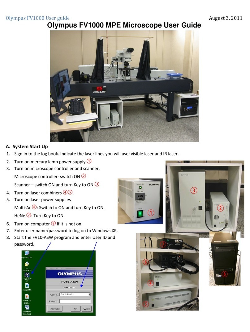
Olympus SZ3060 Operating instructions

Olympus

Olympus SZ3060 Operating instructions

Olympus Fluoview-1000 User manual

Olympus

Olympus Fluoview-1000 User manual

Olympus CKX53 User manual

Olympus

Olympus CKX53 User manual

Olympus BX53M-P User manual

Olympus

Olympus BX53M-P User manual

Olympus CHBS User manual

Olympus

Olympus CHBS User manual

Olympus CK2 User manual

Olympus

Olympus CK2 User manual

Olympus SZ61 User manual

Olympus

Olympus SZ61 User manual

Olympus CKX41 Installation guide

Olympus

Olympus CKX41 Installation guide

Popular Microscope manuals by other brands

Ken A Vision T-1953BP instruction manual

Ken A Vision

Ken A Vision T-1953BP instruction manual

LIMITLESS MagniFlex quick start guide

LIMITLESS

LIMITLESS MagniFlex quick start guide

KERN OBL 146 User instructions

KERN

KERN OBL 146 User instructions

Optika Italy B-510 Series instruction manual

Optika Italy

Optika Italy B-510 Series instruction manual

Leica TCS SP5 X user manual

Leica

Leica TCS SP5 X user manual

Renfert Mobiloskop S Faq

Renfert

Renfert Mobiloskop S Faq

Home Science Tools MI-6000BIN instruction manual

Home Science Tools

Home Science Tools MI-6000BIN instruction manual

Firefly GT820 user manual

Firefly

Firefly GT820 user manual

ICSPI nGauge AFM user manual

ICSPI

ICSPI nGauge AFM user manual

Meiji Techno MT9930 instruction manual

Meiji Techno

Meiji Techno MT9930 instruction manual

NARIKA D20-2112-W0 instruction manual

NARIKA

NARIKA D20-2112-W0 instruction manual

Bresser Junior 8855000 operating instructions

Bresser Junior

Bresser Junior 8855000 operating instructions

Fein Optic HDCAM-WiFi user manual

Fein Optic

Fein Optic HDCAM-WiFi user manual

AMG EVOS quick start guide

AMG

AMG EVOS quick start guide

NARIKA D20-2101-W0 instruction manual

NARIKA

NARIKA D20-2101-W0 instruction manual

Omax M51B user manual

Omax

Omax M51B user manual

KERN OSE-4 Series User instructions

KERN

KERN OSE-4 Series User instructions

Leica ES2 user manual

Leica

Leica ES2 user manual

manuals.online logo
manuals.online logoBrands
  • About & Mission
  • Contact us
  • Privacy Policy
  • Terms and Conditions

Copyright 2025 Manuals.Online. All Rights Reserved.