Olympus U-DA User manual

INSTRUCTIONS
U-DA
DRAWING ATTACHMENT
This instruction manual is for the Olympus Drawing Attachment Model U-DA. To ensure the safety, obtain
optimum performance and to familiarize yourself fully with the use of this attachment, we recommend that
you study this manual thoroughly before operating the microscope. Retain this instruction manual in an
easily accessible place near the work desk for future reference.
A X 5 8 9 0


i
U-DA
IMPORTANT
This attachment employs a UIS (Universal Infinity System) optical design, and should be used only with UIS
microscopes, eyepieces, objectives and condensers for the BX2 series and BX series. Less than optimum perfor-
mance may result if inappropriate accessories are used.
· The U-DA drawing attachment allows the observer to see the paper sheet on the desk top and the specimen image in
a superimposed image so that the specimen image can be drawn easily.
· Only the specimen image can be observed by attaching the light excluding cap.
· The construction for superimposing the sketched image on the specimen image allows the drawing unit to be used in
bright indoors.
· The drawing field diameter can be increased to 220 mm by attaching the optional U-DAL10X drawing lens.
1. The drawing attachment is a precision instrument. Handle it with care and avoid subjecting it to sudden or severe impact.
2. Do not use the drawing attachment where it is subjected to direct sunlight, high temperature and humidity, dust or
vibrations. (The operating temperature range is from 0 to 40oC and the operating humidity range is from 30% to 85%.)
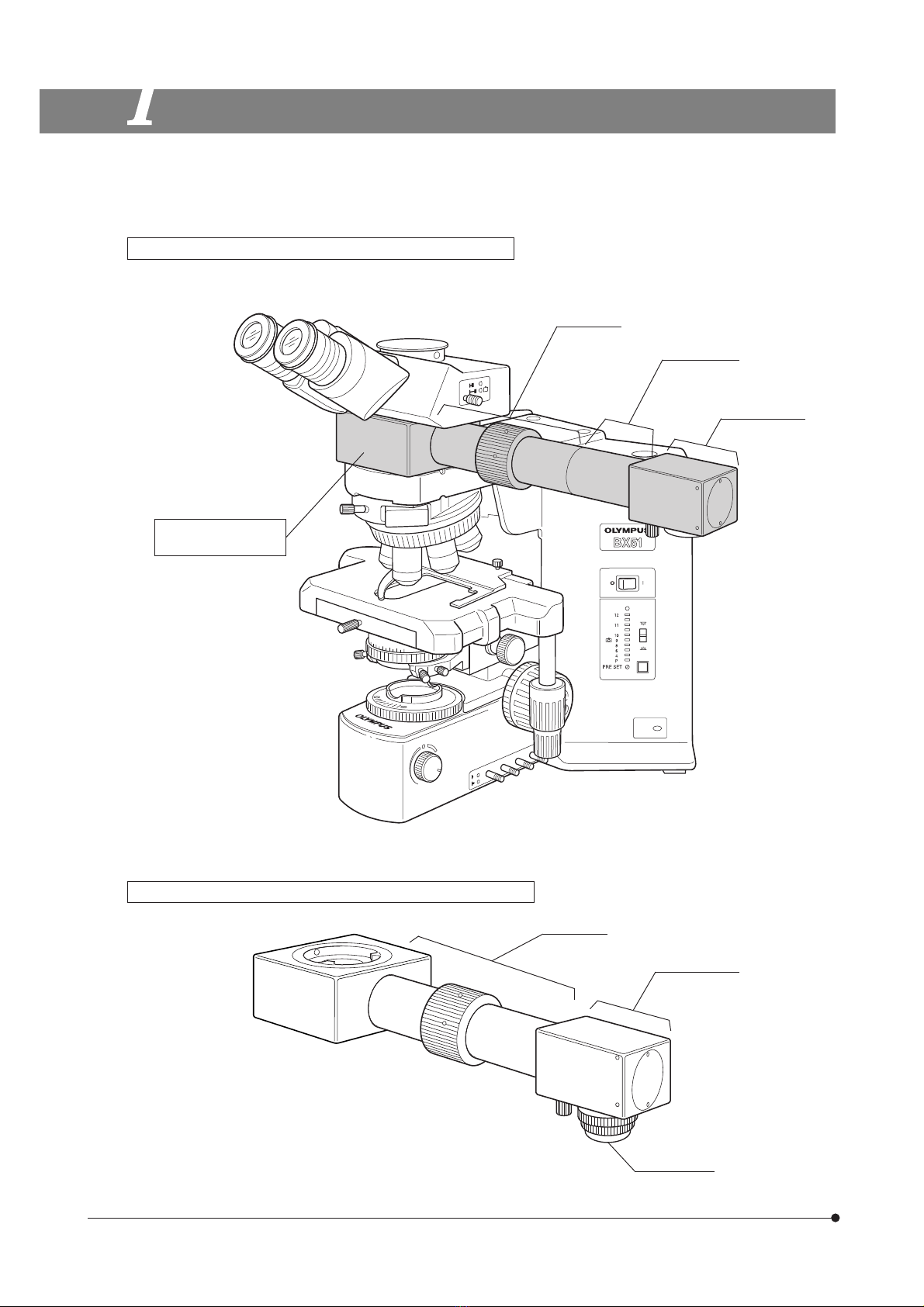
3. Applicable microscopes: BX40, BX50, BX60, BX41, BX45, BX51, BX52.
4. Applicable observation tubes: UIS widefield binocular or trinocular tubes.
# When using a UIS super widefield trinocular tube, there will be no problem in the observed image. Outside the
range of field number 22, however, the tip of the pen tip will not visible or the sketched image will look distorted.
5. Applicable stages (BX series): When drawing on the right side of the microscope with a right-hand drive control stage
mounted, the rack will enter the field of view when the rack is moved all the way to the right and drawing will be made
difficult. It is recommended to use a stage with drive controls placed on the opposite side to the side of the drawing
attachment direction.
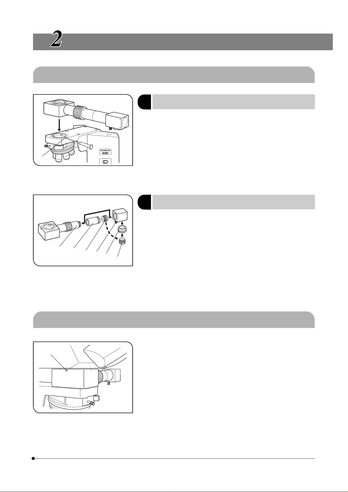
6. When used with the BX40, BX50, BX41, BX51 or BX52, this attachment another intermediate attachment can be used with
one additional intermediate tube. The eyepoint adjuster (U-EPA or U-EPA2), magnification changer (U-CA or U-ECA), dual-
viewing attachment (U-DO or U-DO3), multi-viewing attachment (U-MDO or U-MDO3) or side-by-side viewing attachment
(U-SDO or U-SDO3) may be mounted above the drawing attachment. The intermediate tubes which can be installed
below are indicated in the figure on the next page.
1Getting Ready

ii
Observation tube
Microscope frame
BX40
BX50
Drawing attachment
U-DA
Magnification
changer
U-CA
U-ECA
Intermediate
tube
for AN360
U-OPA
Polarized light
intermediate
tube
U-CPA
Reflected
illuminator
U-RLA
Universal
illuminator
BX-URA2
Fluorescence
lluminator
BX-RFA
Microscope frame
BX41
BX51
BX52
Microscope frame
BX60
BX45
Universal
illuminator
U-URA
1. To clean the lenses and other glass components, simply blow dirty away using a commercially available blower and wipe
gently using a piece of cleaning paper (or clean gauze).
If a lens is stained with fingerprints or oil smudges, wipe it gauze slightly moistened with commercially available absolute
alcohol.
Since the absolute alcohol is highly flammable, it must be handled carefully.
Be sure to keep it away from open flames or potential sources of electrical sparks --- for example, electrical
equipment that is being switched on or off.
Also remember to always use it only in a well-ventilated room.
2. Never wipe the mirror with gauze, etc. Fine dust accumulated on the surface should be blown off with a blower.
3. When not using the attachment, attach the light excluding cap to the mirror housing and keep the attachment covered
with a dust cover.
2Maintenance and Storage
If the equipment is used in a manner not specified by this manual, the safety of the user may be imperiled. In addition, the
equipment may also be damaged. Always use the equipment as outlined in this instruction manual.
The following symbols are used to set off text in this instruction manual.
: Indicates that failure to follow the instructions in the warning could result in bodily harm to the
user and/or damage to equipment (including objects in the vicinity of the equipment).
# : Indicates that failure to follow the instructions could result in damage to the equipment.
} : Indicates commentary (for ease of operation and maintenance).
3Caution

U-DA
1
2
1NOMENCLATURE
2ASSEMBLY
2-1 Mounting the Drawing Attachment on the Microscope ................................................................. 2
2-2 Mounting the Observation Tube ........................................................................................................................................ 2
3OPERATION
4SPECIFICATIONS
3
5
CONTENTS

1
1
NOMENCLATURE
1. When only the U-DA is mounted on the microscope frame
}The configuration is identical even when another intermediate is mounted above the U-DA.
Relay tube
Mirror housing
Drawing Attachment
(U-DA)
2. When the U-DA is mounted above another intermediate tube
Drawing lens
Adapter tube
}Depending on the mounting position of the U-DA, the adapter tube may become unnecessary, in which case the drawing
lens has to be remounted.
Mirror housing
Relay tube

U-DA
2
Fig. 3
Fig. 2
Fig. 1
1. Using the Allen screwdriver provided with the microscope frame, fully
loosen the clamping screw @ on the microscope frame.
2. Insert the circular dovetail mount at the bottom of the drawing attachment
into the mount on the microscope frame.
3. Rotate the dovetail so the drawing attachment’s mirror housing is point-
ing either to the left or right side when looking at the microscope from the
front. (Fig. 1 shows the right-hand installation.)
4. Using the Allen screwdriver, fully tighten the clamping screw @.
# The lens adapter frame (ƒ in Fig. 2) should not be used as it will
cause vignetting of the sketched image.
1. Fully loosen the mirror housing clamping knob ² and detach the mirror
housing.
2. Remove the drawing lens | screwed into the adapter tube ³.
3. Unscrew and remove the adapter tube ³.
# The removed adapter tube ³ is not used in this mounting procedure.
4. Screw the lens adapter frame ƒ, provided with the U-DA, into the threaded
hole at the bottom of the mirror housing.
5. Screw the drawing lens | removed in step 2 above, into the lens adapter
frame ƒ.
6. Attach the drawing attachment on the existing intermediate tube.
7. Insert the mirror housing into the relay tube … and tighten the mirror
housing clamping knob ².
ASSEMBLY
2-1 Mounting the Drawing Attachment on the Microscope
@
1(Fig. 1)
When the U-DA is mounted above another
intermediate tube
2(Fig. 2)
1. Using the Allen screwdriver, fully loosen the clamping screw @ of the
drawing attachment (or another intermediate tube).
2. Insert the circular dovetail mount at the observation tube into the mount
on the drawing attachment.
3. Using the Allen screwdriver, securely tighten the clamping screw @ again.
2-2 Mounting the Observation Tube (Fig. 3)
²
³ƒ|
…|
@
When only the U-DA is mounted on the
microscope frame

3
Fig. 4
OPERATION
Place drawing paper horizontally on the desktop exactly below the mirror
in the mirror housing. The paper should be secured after alignment.
1. Loosen the mirror housing clamping knob @ and rotate the mirror hous-
ing until it is positioned perpendicularly to the drawing paper.
2. Clamp the mirror tube by tightening the clamping knob @.
Operate the coarse and fine adjustment knobs on the microscope to
focus on the specimen.
When drawing, detach the light excluding cap ² from the mirror tube
bottom.
@
1Positioning the Drawing Paper
2Adjusting the Mirror Housing (Fig. 4)
3Focusing on the Specimen
4Removing the Light Excluding Cap (Fig. 4)
5Focusing the Drawing Paper (Fig. 4)
Rotate the focusing collar ³ on the drawing attachment to focus on the
drawing paper.
6Determining the Drawing Projection Magnification
1. Place an objective micrometer on the stage and a scale on the drawing
paper surface. While looking through the eyepiece, find the place where
the objective micrometer graduations and scale graduations match pre-
cisely.
Drawing projection magnification = Scale reading
Objective micrometer reading
#Match the units.
2. When an objective micrometer is not available, place a scale on the draw-
ing paper as in step 1 and read the diameter of the drawing field.
Drawing projection magnification =
Drawing field diameter (mm)
Eyepiece field number x Objective magnification
The specimen sketch drawn on the paper will conform to this magni-
fication.
}After using either of the methods described in steps 1 and 2 to find the
drawing projection magnification, it is recommended to draw a scale on
the drawing paper so that the specimen size can always be determined
with ease. If an objective micrometer is available, drawing its scale on the
paper will further simplify the procedure.
²
³

U-DA
4
Fig. 7
Fig. 6
Fig. 5
@
7(Fig. 5)
Adjusting the Brightness Balance of
Drawn Image and Specimen Image
²
³
|
@
2. When the U-DA is mounted above another intermediate tube (Fig. 7)
1. Loosen the mirror housing clamping knob @ and detach the mirror hous-
ing.
2. Remove the adapter tube ² by screwing. The standard drawing lens
attached to the adapter tube will not be used in the present procedure.
3. Attach the mirror housing directly to the relay tube ƒ.
4. Screw in the lens adapter frame …, provided with the U-DA, into the threaded
hole at the mirror housing bottom.
5. Screw in the 10X drawing lens ³.
How to Use
The same operation as with the standard drawing lens is possible.
²
³
ƒ
@
…
²
1. While looking through the eyepiece, place a pencil, etc. on the drawing
paper surface.
2. Using the microscope’s brightness adjustment knob @, adjust the bright-
ness until the tip of the pencil and the specimen can be seen clearly at the
same time.
}If the drawing paper surface is dark, drawing will be made easier by illumi-
nating the paper with an electric lamp.
}If the microscope’s light preset button ² is set to the optimum brightness
position for drawing and if, when the light preset button is OFF, the bright-
ness is set to the darkest position, it will be possible to switch between the
image of the superimposed specimen and drawing and the drawing
image alone just by pressing the button.
Options
Using the 10X Drawing Lens (U-DAL10X)
}When the optional 10X drawing lens is used in place of the standard
drawing lens, the drawing field diameter can be expanded to 220 mm,
which means that the image can be projected to almost fill an A4-size
page.
How to Attach
1. When only the U-DA is mounted on the microscope frame (Fig. 6)
1. Loosen the mirror housing clamping knob @ and detach the mirror hous-
ing.
2. Remove the standard drawing lens which is screwed into the adapter
tube ², and attach the 10X drawing lens ³ and the ring | provided with
the 10X drawing lens in place.

5
SPECIFICATIONS
Item Specification
(1) Tube magnification 1X
(2) Maximum field number 22 (mm )
(3) Drawing image magnification 16X (When there is an intermediate tube between the microscope and
drawing attachment, the magnification may be variable by ±3%.)
10X (When the U-DAL10X is used)
(4) Drawing field 352 mm ( 220 mm when the U-DAL10X is used)
(5) Focusing (on paper) Focusing collar system
(6) Optical axis height BX40, BX50: 330.5 mm (When an additional intermediate tube is com-
bined, add the thickness of the intermediate tube.)
BX41: 333. 5 mm.
BX51, BX52 (Transmitted light specification): 340.5 mm (When an addi-
tional intermediate tube is combined, add the thickness
of the intermediate tube.)
(7) Focusing range Below desktop surface: About 50 cm
Above desktop surface: Up to near the mirror housing bottom.
(The magnification is variable.)


AX5890 04
8F Olympus Tower, 446 Bongeunsa-ro, Gangnam-gu, Seoul, Korea 135-509
Distributed by
Shinjuku Monolith, 2-3-1 Nishi-Shinjuku, Shinjuku-ku, Tokyo 163-0914, Japan
Manufactured by
Table of contents
Other Olympus Microscope manuals

Olympus
Olympus BHSP User manual

Olympus
Olympus CKX53 User manual

Olympus
Olympus Fluoview FV1000 Instruction Manual

Olympus
Olympus BH2-5RE Installation instructions

Olympus
Olympus BHTP User manual

Olympus
Olympus bx40 User manual

Olympus
Olympus BH2-CH Substage User manual

Olympus
Olympus CK30 User manual

Olympus
Olympus FV3000 User manual

Olympus
Olympus IX2-RFSPOT User manual

Olympus
Olympus BHS User manual

Olympus
Olympus IX70 User manual

Olympus
Olympus CH30 User manual

Olympus
Olympus U-D7RES User manual

Olympus
Olympus SZ-III User manual

Olympus
Olympus IMT-2-11 User manual

Olympus
Olympus bx40 User manual

Olympus
Olympus SZX-AR1 User manual

Olympus
Olympus BX3-SSU User manual

Olympus
Olympus FHT-521 User manual