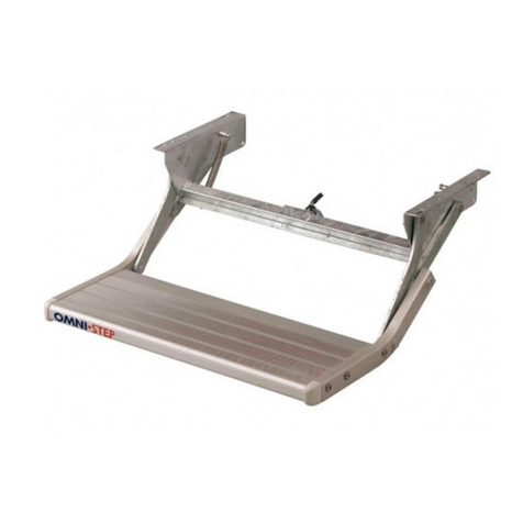
MONTAGEVOORSCHRIFTEN
Lees deze montagevoorschriften aandachtig. Bij verkeerde
montage of gebruik vervalt elke aanspraak op garantie.
Om te voldoen aan de normen EN 1646-1 (motorhomes) en EN
1645-1 (caravans), mag de uitgestoken trede niet hoger dan 400
mm van de grond komen en moet ze op 200 tot 300 mm van de
volgende trede liggen.
INHOUD BEVESTIGINGSKIT
Zeskantbouten DIN 933 - M8 x 50.................................4
Sluitringen DIN 125 - M8 ...............................................8
Borgmoeren DIN 985 - M8.............................................4
MONTAGE VAN DE STEP
Deze montagevoorschriften gelden enkel als leidraad.
Naargelang het type voertuig kan de bevestiging van de
OMNISTEP op verschillende manieren gebeuren (fig. 2):
- dwars doorheen de vloer,
- in ancrarails die in de bodem ingewerkt zijn,
- op een speciale constructie die aan het chassis gelast of
gebout wordt.
De montageafmetingen vindt men terug op fig. 1 en 1bis.
AANSLUITING WAARSCHUWINGSLAMPJE (fig. 3)
Op de OMNISTEP staat een schakelaar (S2) gemonteerd
die ingedrukt wordt als de trede ingetrokken is. Aan deze
schakelaar kan een waarschuwingslampje (L) op het
dashboard aangesloten worden dat brandt bij het starten van
het voertuig als de trede uitstaat.
Hiervoor wordt stroom genomen:
a) van de klem van de elektrische toebehoren (stand 1)
van het sleutelcontact of
b) van het relais dat werkt bij het aanleggen van het
sleutelcontact. De klem uitzoeken die hierbij positief
wordt.
Verbind deze bepaalde klem via het verkliklampje met de
schakelaar.
GEBRUIK (fig. 4)
- Het uittrekken van de trede gebeurt met de hand. Men trekt
onderaan aan de boord van de trede.
- Het induwen van de trede kan met de voet gebeuren door
de trede lichtjes naar omhoog te tillen.
INSTRUCTIONS DE MONTAGE
Lisez cette notice attentivement. Un montage ou un usage fautif
annule toutes les clauses de garantie.
Pour satisfaire aux normes EN 1646-1 (camping-cars) et EN
1645-1 (caravanes), la marche déployée ne peut être supérieure
à 400 mm du sol et doit se situer entre 200 et 300 mm de la
marche supérieure.
CONTENU DU KIT DE MONTAGE
Vis à tête hexagonale DIN 933 - M8 x 50 ......................4
Rondelles DIN 125 - M8 ................................................8
Ecrous de sûreté DIN 985 - M8 .....................................4
MONTAGE DU MARCHEPIED
Ces instructions ne sont pas imposées, mais vous servent
de guide. Selon le type du véhicule la fixation de
l'OMNISTEP peut se faire de manières différentes (fig. 2):
- à travers le plancher,
- dans les profilés incorporés dans le plancher,
- sur une construction spécialement soudée ou boulonnée
au châssis.
Les dimensions de montage sont montrés sur fig. 1 et 1bis.
RACCORDEMENT D'UNE LAMPE TEMOIN (fig. 3)
Le marchepied est pourvu d'un interrupteur (S2) qui est
poussé par le marchepied lors de son entrée. Une lampe
témoin (L) s'allumant quand le marchepied est sorti, peut
être branchée à cet interrupteur.
Prenez du courant:
a) de la fiche des accessoires électriques de la cléf de
contact ou
b) du relais qui est actionné en mettant le véhicule en
marche. Cherhez une fiche qui devient positive.
Branchez cette fiche par la lampe témoin à l'interrupteur.
MODE D'EMPLOI (fig. 4)
- Pour sortir le marche-pied, tirez la marche par le dessous
avec la main.
- Pour entrer le marche-pied, levez la marche légèrement
avec le pied.
MONTAGEANLEITUNG
ACHTUNG: Lesen Sie die Montageanleitung sorgfältig durch, da
bei unsachgemässer Montage der Garantieanspruch erlischt.
Um die Normen EN 1646-1 (Reisemobile) und EN 1645-1
(Caravans) zu entsprechen, darf die erste Stufe eine Höhe vom
400 mm, gemessen vom Boden aus, nicht überschreiten. Eine
weitere Stufe muss eine Höhe von 250 mm ± 50 mm haben.
INHALT BEFESTIGUNGSSATZ
Sechseckige Schrauben DIN 933 - M8 x 50..................4
Unterlegscheiben DIN 125 - M8 ....................................8
Sicherungsmuttern DIN 985 - M8..................................4
EINBAU DER TRITTSTUFE
Diese Montageanleitungen sind nur Anweisungen. Der
Anbau der Trittstufe kann - je nach Fahrzeugtype - auf
verschiedene Arten erfolgen (siehe Fig. 2):
- am Boden des Fahrzeuges,
- in Schienen, die in den Boden eingebaut werden,
- auf einer speziellen Konstruktion, die ans Fahrwerk
geschweisst oder gebolzt wird.
Die Maβe für die Montage finden Sie in Fig. 1 und 1bis
zurück.
ANSCHLUSS WARNUNGSLAMPE (Fig. 3)
An der Trittstufe ist ein Schalter (S2), der beim Einfahren der
Stufe eingedrückt wird. Dieser Schalter kann mit einer
Warnungslampe (L) verbunden werden, die bei
ausgefahrener Stufe aufleuchtet.
Dazu wird Strom abgenommen:
a) an der Klemme am Zündschalter, die die elektrischen
Zubehörteile mit Strom versieht oder
b) vom Relais, das bei Bedienung des Schlüsselkontakts
funktioniert. Suchen Sie die Klemme, die positiv wird.
Diese Klemme über die Warnungslampe mit dem Schalter
verbinden.
GEBRAUCH (Fig. 4)
- Das Öffnen der Trittstufe erfolgt manuell. Ziehen Sie am
unteren Rand der Trittstufe.
- Zum Schliessen der Stufe heben Sie die Trittstufe mit dem
Fuss ein wenig hoch.
Thule nv - Kortrijkstraat 343 – BE 8930 Menen
2S 902-05
Prod.nr. 20 2055 00
