manuals.online logo
Brands
  1. Home
  2. •
  3. Brands
  4. •
  5. Omron
  6. •
  7. Accessories
  8. •
  9. Omron E3Z-G User manual

Omron E3Z-G User manual

1
E3Z-G
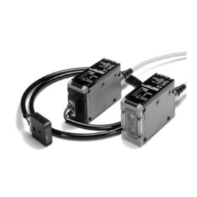
Grooved-type Photoelectric Sensor
■Grooved design eliminates the need for optical
axis adjustment.
■Two-axis models also available.
■Ideal for detection and positioning for cranes and
conveyor systems in automated warehouses.
Ordering Information
■Sensor Unit
Note: Models with a 0.5-m cable are available. When ordering, specify the cable length by adding the code “0.5M” to the model number
(e.g., E3Z-G61 0.5M).
■Accessories (Order Separately)
Sensor I/O Connector
Specifications
■Ratings/Characteristics
Sensing
method
Appearance Connection method Sensing distance Number of
optical axes
Model
NPN output PNP output
Through-
beam
Pre-wired (0.5/2 m) 1 E3Z-G61 E3Z-G81
Junction connector E3Z-G61-M3J E3Z-G81-M3J
Pre-wired (0.5/2 m) 2 E3Z-G62 E3Z-G82
Junction connector E3Z-G62-M3J E3Z-G82-M3J
25 mm
Cable
specifications
Appearance Type of cable Model
Standard cable 2 m Four-core cable XS3F-M421-402-A
5 m XS3F-M421-405-A
2 m XS3F-M422-402-A
5 m XS3F-M422-405-A
Sensing method Through beam (grooved type)
Number of optical axes 1 2
NPN output E3Z-G61 E3Z-G61-M3J E3Z-G62 E3Z-G62-M3J
Item PNP output E3Z-G81 E3Z-G81-M3J E3Z-G82 E3Z-G82-M3J
Sensing distance 25 mm (distance between arms of groove)
Light source (wave length) Infrared LED (940 nm)
Power supply voltage 12 to 24 VDC±10% including 10% (p-p) max. ripple
Current consumption 25 mA max. 40 mA max.
Control output Load power supply voltage: 26.4 VDC max.
Load current: 100 mA max. (Residual voltage: 1 V max.)
L-ON/D-ON selectable (With 2-axis models, L-ON or D-ON can be selected for each axis.)
Circuit protection Protection from reversed power supply connection, output short-circuits, and mutual interfer-
ence.
Response time Operation or reset: 1 ms max.
Straight
L-shape
2
E3Z-GE3Z-G
Operation
■Output Circuits (NPN Output)
Sensing method Through beam (grooved type)
Number of optical axes 1 2
NPN output E3Z-G61 E3Z-G61-M3J E3Z-G62 E3Z-G62-M3J
Item PNP output E3Z-G81 E3Z-G81-M3J E3Z-G82 E3Z-G82-M3J
Ambient illumination (receiver side) Incandescent lamp: 3,000 lux max.
Sunlight: 10,000 lux max.
Ambient temperature Operating: −25 to 55°C/Storage: −40 to 70°C (with no icing or condensation)
Ambient humidity Operating: 35% to 85%/Storage: 35% to 95% (with no condensation)
Insulation resistance 20 MΩmin. at 500 VDC between lead wires and case
Dielectric strength 1,000 VAC, 50/60 Hz for 1 min between lead wires and case
Vibration resistance (destruction) 10 to 55 Hz, 1.5-mm double amplitude for 2 hours each in X, Y, and Z directions
Shock resistance (destruction) 500 m/s23 times each in X, Y, and Z directions
Enclosure rating IP64 (IEC60529)
Connection method Pre-wired cable
(length: 2 m or 0.5 m)
Junction connector Pre-wired cable
(length: 2 m or 0.5 m)
Junction connector
Indicator Operation indicator (orange)
Weight (packed state) Pre-wired models (with 2-m cable): 65 g
Models with junction connectors: 30 g
Material ABS
Accessories Instruction sheet
No. of
optical
axes/model
Out-
put
tran-
sistor
status
Timing chart Mode
selector
Output circuit
1 axis
E3Z-G61
E3Z-G61-
M3J
Light
ON
LIGHT
ON
(L/ON)
Dark
ON
DARK
ON
(D/ON)
2 axes
E3Z-G62
E3Z-G62-
M3J
Light
ON
LIGHT
ON
(L/ON)
Dark
ON
DARK
ON
(D/ON)
Incident
Interrupted
ON
OFF
ON
OFF
Operate
Reset
Operation
indicator
(orange)
(Between brown and black)
Output
transistor
Load
(relay)
4
3
12 to 24 VDC
Brown
Black
(S1)
(Control output)
Blue
100 mA max.
Operation
indicator
(orange)
0 V
ZD
Load
(relay)
Main
circuit
1
Connecting Pin Arrangement
Note: Pin 2 is not used.
1
24
3
Incident
Interrupted
ON
OFF
ON
OFF
Operate
Reset
Operation
indicator
(orange)
(Between brown and black)
Output
transistor
Load
(relay)

Incident
Interrupted
ON
OFF
ON
OFF
Operate
Reset
Operation
indicator
(orange)
(Between brown and black)
Output
transistor
Load
(relay)
(S1)
(S2)
4
3
112 to 24 VDC
Brown
Black
(Control
output)
Blue
100 mA max.
Operation
indicator
S1
(orange)
Operation
indicator
S2
(orange)
0 V
Z
D
Load
(relay)
2
White
(Control
output)
Z
D
Load
(relay)
Main
circuit
Connector Pin Arrangement
1
24
3
100 mA max.
Incident
Interrupted
ON
OFF
ON
OFF
Operate
Reset
Operation
indicator
(orange)
(Between brown and black)
Output
transistor
Load
(relay)
3
E3Z-GE3Z-G
■Output Circuits (PNP Output)
Structure of Sensor I/O Connector
Note: Pin 2 of 1-axis models is not used.
No. of
optical
axes/model
Out-
put
tran-
sistor
status
Timing chart Mode
selector
Output circuit
1 axis
E3Z-G81
E3Z-G81-
M3J
Light
ON
LIGHT
ON
(L/ON)
Dark
ON
DARK
ON
(D/ON)
2 axes
E3Z-G82
E3Z-G82-
M3J
Light
ON
LIGHT
ON
(L/ON)
Dark
ON
DARK
ON
(D/ON)
Incident
Interrupted
ON
OFF
ON
OFF
Operate
Reset
Operation
indicator
(orange)
(Between brown and black
)
Output
transistor
Load
(relay)
4
3
12 to 24 VDC
Brown
Black
(S1)
(Control output)
Blue
100 mA max.
Operation
indicator
(orange)
0 V
ZD
Load
(relay)
Main
circuit
1
Connector Pin Arrangement
Note: Pin 2 is not used.
1
24
3
Incident
Interrupted
ON
OFF
ON
OFF
Operate
Reset
Operation
indicator
(orange)
(Between brown and black
)
Output
transistor
Load
(relay)
Incident
Interrupted
ON
OFF
ON
OFF
Operate
Reset
Operation
indicator
(orange)
(Between brown and black
)
Output
transistor
Load
(relay) (S2)
4
3
112 to 24 VDC
Brown
Black (S1)
(Control
output)
Blue
100 mA
max.
Operation
indicator
S1
(orange)
Operation
indicator
S2
(orange)
Z
D
Load
(relay)
2
100 mA
max.
White
(Control
output)
Z
D
Load
(relay)
Main
circuit
Connector Pin Arrangement
1
24
3
0 V
Incident
Interrupted
ON
OFF
ON
OFF
Operate
Reset
Operation
indicator
(orange)
(Between brown and black
)
Output
transistor
Load
(relay)
2
4
1
3
1
2
3
4
Brown
White
Blue
Black
XS3F-M421-402-A
XS3F-M421-405-A
XS3F-M422-402-A
XS3F-M422-405-A
Wire color
Classification Wire color Connector
pin number
Use
1-axis
models
2-axis
models
DC Brown 1 Power supply (+V)
White 2 --- Output 2 (S2)
Blue 3 Power supply (0 V)
Black 4 Output Output 1 (S1)
4
E3Z-GE3Z-G
Dimensions
Mode selector
Note: Both 1 and 2-axis models have S1; only 2-axis models have S2.
S1 output: black
S2 output: white
36
20
40
Operation indicator (orange)
257.511
40
19
9
35
50
4-dia., 4-core vinyl-insulated round cable
(Conductor cross-section: 0.2 mm
2
; insulator diameter: 1.1 mm)
Standard lengths: 2 m, 0.5 m
Two, 4.5 dia.
Optical axis S1 (see note) Optical axis S2 (see note)
4-dia., 4-core vinyl-insulated round cable
Standard length: 0.3 m
M8
24
13
Junction Connector Models
(E3Z-G6
@
-M3J)
S1
S2
In the interest of product improvement, specifications are subject to change without notice.
ALL DIMENSIONS SHOWN ARE IN MILLIMETERS.
To convert millimeters into inches, multiply by 0.03937. To convert grams into ounces, multiply by 0.03527.
Cat. No. E320-E1-1
OMRON Corporation
Industrial Automation Company
Industrial Sensors Division
Sensing Devices and Components Division H.Q.
Shiokoji Horikawa, Shimogyo-ku
Kyoto, 600-8530 Japan
Tel: (81)75-344-7068/Fax: (81)75-344-7107
Printed in Japan
0501-1M (A)

This manual suits for next models

8

Other Omron Accessories manuals

Omron ZX2-LDA User manual

Omron

Omron ZX2-LDA User manual

Omron ZFX-C20 User manual

Omron

Omron ZFX-C20 User manual

Omron F3W-D052C Series User manual

Omron

Omron F3W-D052C Series User manual

Omron Z4W-V User manual

Omron

Omron Z4W-V User manual

Omron ZFX-C User manual

Omron

Omron ZFX-C User manual

Omron E3X-DA11TW User manual

Omron

Omron E3X-DA11TW User manual

Omron ES1 N Series User manual

Omron

Omron ES1 N Series User manual

Omron ZX-E Series User manual

Omron

Omron ZX-E Series User manual

Omron E3S-CR62 - User manual

Omron

Omron E3S-CR62 - User manual

Omron Z4LB V2 User manual

Omron

Omron Z4LB V2 User manual

Omron fh series User manual

Omron

Omron fh series User manual

Omron ZN-TH11-S User manual

Omron

Omron ZN-TH11-S User manual

Omron F3C Series User manual

Omron

Omron F3C Series User manual

Omron XPECTIA FZ3 User manual

Omron

Omron XPECTIA FZ3 User manual

Omron F3W-D User manual

Omron

Omron F3W-D User manual

Omron ZX-T - User manual

Omron

Omron ZX-T - User manual

Omron E3Z series User manual

Omron

Omron E3Z series User manual

Omron E3X-N User manual

Omron

Omron E3X-N User manual

Omron F160-2 -  2 User manual

Omron

Omron F160-2 - 2 User manual

Omron E3FS-10B4 2M User manual

Omron

Omron E3FS-10B4 2M User manual

Omron E3K User manual

Omron

Omron E3K User manual

Omron ZFX-C-CD User manual

Omron

Omron ZFX-C-CD User manual

Omron ZX-GT - User manual

Omron

Omron ZX-GT - User manual

Omron F3UV-A30 User manual

Omron

Omron F3UV-A30 User manual

Popular Accessories manuals by other brands

ProMinent DULCOTEST ICT 1 operating instructions

ProMinent

ProMinent DULCOTEST ICT 1 operating instructions

Garmin GPSMAP 5008 - Marine GPS Receiver printing guide

Garmin

Garmin GPSMAP 5008 - Marine GPS Receiver printing guide

USA Measurements US-5011 User's & technical manual

USA Measurements

USA Measurements US-5011 User's & technical manual

Windsor 8.631-213.0 Operator instructions

Windsor

Windsor 8.631-213.0 Operator instructions

ACR Electronics FPR-10 PROGRAMMER Product support manual

ACR Electronics

ACR Electronics FPR-10 PROGRAMMER Product support manual

Philips HS85 Specifications

Philips

Philips HS85 Specifications

Huawei RAN12.0 DBS3800 Product description

Huawei

Huawei RAN12.0 DBS3800 Product description

Swann dc835p instruction manual

Swann

Swann dc835p instruction manual

Vivint VS-PIR3-345 quick reference

Vivint

Vivint VS-PIR3-345 quick reference

Jaypro Sports LS-200RS installation instructions

Jaypro Sports

Jaypro Sports LS-200RS installation instructions

Qvis DoorProtect user manual

Qvis

Qvis DoorProtect user manual

Malmet Energy Saver ES910 Operation, maintenance and installation manual

Malmet

Malmet Energy Saver ES910 Operation, maintenance and installation manual

Movisens Move II user manual

Movisens

Movisens Move II user manual

Mightymast Leisure 6ft Pentagon Assembly instructions

Mightymast Leisure

Mightymast Leisure 6ft Pentagon Assembly instructions

Philio PHI PST02-1B quick start guide

Philio

Philio PHI PST02-1B quick start guide

TUYA 96236 Quick user guide

TUYA

TUYA 96236 Quick user guide

Swann SWIFI-LEAK quick start guide

Swann

Swann SWIFI-LEAK quick start guide

NewerTech AdaptaDrive user guide

NewerTech

NewerTech AdaptaDrive user guide

manuals.online logo
manuals.online logoBrands
  • About & Mission
  • Contact us
  • Privacy Policy
  • Terms and Conditions

Copyright 2025 Manuals.Online. All Rights Reserved.