Omron F3SJ-A series User manual

439
19 Safety sensors
F3SJ-A Safety sensors
Small housing safety light curtain
The F3SJ_A - family is a type 4 safety light curtain with a optical resolution of 14 mm
and 30 mm. An operating range of up to 9 m and protective heights up to 2,495 mm
are provided with no dead zone.
• Detection heigth = sensor height
• Muting and blanking function available
• LED bar for easy alignment and diagnosis
• Type 4 sensor complying with EN 61496-1 and up to
PLe according EN ISO 13849-1
Ordering information
Safety Light Curtain
Safety Light Curtain Model List
F3SJ-A14 Series (9 mm gap), F3SJ-A14 TS Series (9 mm gap)*1
*1. The suffix "-TS" is attached to the model number of models with fixed auto reset.
(Only for PNP output)
*2. Protective Height (mm) = Total sensor length
F3SJ-A30 Series (25 mm gap)
Application Detection capability Beam gap Operating range Protective height (mm) Order code
PNP output
Finger protection Dia. 14 mm 9 mm 0.2 to 9 m 245 to 1,631 F3SJ-A____P14
Hand/arm protection Dia. 30 mm 25 mm 0.2 to 9 m 245 to 1,620 F3SJ-A____P30
0.2 to 7 m 1,745 to 2,495
Number of Beams Protective Height (mm)*2 Order code
PNP Output*1
26 245 F3SJ-A0245P14
28 263 F3SJ-A0263P14
34 317 F3SJ-A0317P14
42 389 F3SJ-A0389P14
50 461 F3SJ-A0461P14
60 551 F3SJ-A0551P14
68 623 F3SJ-A0623P14
76 695 F3SJ-A0695P14
80 731 F3SJ-A0731P14
88 803 F3SJ-A0803P14
96 875 F3SJ-A0875P14
108 983 F3SJ-A0983P14
116 1,055 F3SJ-A1055P14
124 1,127 F3SJ-A1127P14
132 1,199 F3SJ-A1199P14
140 1,271 F3SJ-A1271P14
Number of Beams Protective Height (mm)*1
*1 Protective Height (mm) = Total sensor length
Order code
PNP Output
10 245 F3SJ-A0245P30
12 295 F3SJ-A0295P30
16 395 F3SJ-A0395P30
19 470 F3SJ-A0470P30
21 520 F3SJ-A0520P30
22 545 F3SJ-A0545P30
23 570 F3SJ-A0570P30
25 620 F3SJ-A0620P30
29 720 F3SJ-A0720P30
32 795 F3SJ-A0795P30
35 870 F3SJ-A0870P30
37 920 F3SJ-A0920P30
38 945 F3SJ-A0945P30
41 1,020 F3SJ-A1020P30
44 1,095 F3SJ-A1095P30
45 1,120 F3SJ-A1120P30
48 1,195 F3SJ-A1195P30
51 1,270 F3SJ-A1270P30
56 1,395 F3SJ-A1395P30
65 1,620 F3SJ-A1620P30
70 1,745 F3SJ-A1745P30
75 1,870 F3SJ-A1870P30
80 1,995 F3SJ-A1995P30
90 2,245 F3SJ-A2245P30
95 2,370 F3SJ-A2370P30
100 2,495 F3SJ-A2495P30

F3SJ-A Safety sensors
440
Accessories (Sold separately)
Single-end Connector Cable (2 cables per set, for emitter and receiver)
For wiring with safety circuit such as single safety relay, safety relay unit, and safety controller.
Sensor Mounting Brackets (Sold separately)
Appearance Cable length Specifications Order code
0.5 m M12 connector (8-pin) F39-JCR5A
3 m F39-JC3A
7 m F39-JC7A
10 m F39-JC10A
15 m F39-JC15A
20 m F39-JC20A
Appearance Specifications Application Remarks Order code
Standard mounting bracket
(for top/bottom)
(provided with the F3SJ) 2 for an emitter, 2 for a receiver,
total of 4 per set
F39-LJ1
Flat side mounting bracket Use these small-sized brackets when performing
side mounting with standard mounting brackets,
so that they do not protrude from the detection
surface.
2 for an emitter, 2 for a receiver,
total of 4 per set
F39-LJ2
Free-location mounting
bracket
(also used as standard inter-
mediate bracket)
Use these brackets for mounting on any place
without using standard bracket.
Two brackets per set F39-LJ3
F3SN Intermediate Bracket
Replacement Spacers
When replacing the F3SN with the F3SJ, the
mounting hole pitches in the Intermediate Brack-
ets are not the same. This Spacer is placed be-
tween the mounting holes to mount the F3SJ.
1 set with 2 pieces F39-LJ3-SN
Top/bottom bracket B
(Mounting hole pitch 19 mm)
Mounting bracket used when replacing existing
area sensors (other than F3SN or F3WN) with the
F3SJ.
For front mounting.
Suitable for mounting hole pitch of 18 to 20 mm.
2 for an emitter, 2 for a receiver,
total of 4 per set
F39-LJ4
Bracket for replacing
short-length F3SN
Mounting bracket used when an F3SN with pro-
tective height of 300 mm or less is replaced by
an F3SJ.
2 for an emitter, 2 for a receiver,
total of 4 per set
F39-LJ5
Space-saving mounting
bracket
Use these brackets to mount facing inward.
Length is 12 mm shorter than the standard
F39-LJ1 bracket.
2 for an emitter, 2 for a receiver,
total of 4 per set
F39-LJ8
Top/bottom bracket C
(mounting hole pitch 13 mm)
Mounting bracket used when replacing existing
area sensors having a mounting pitch of 13 mm
with the F3SJ.
2 for an emitter,
2 for a receiver,
total of 4 per set
F39-LJ11

F3SJ-A Safety sensors
441
19 Safety sensors
Specifications
F3SJ-A____P14/P30
Model PNP Output F3SJ-A____P14 F3SJ-A____P30
Sensor type Type 4 safety light curtain
Version Ver. 2
Setting tool connection Connectable
Safety category Safety purpose of category 4, 3, 2, 1, or B
Detection capability Opaque objects 14 mm in diameter Opaque objects 30 mm in diameter
Beam gap (P) 9 mm 25 mm
Number of beams (n) 26 to 180 10 to 100
Protective height (PH) 245 to 1,631 mm 245 to 2,495 mm
Lens diameter Diameter 5 mm
Operating range 0.2 to 9 m (protective height 1,640 mm max.), 0.2 to 7 m (protective height 1,655 mm min.)
(Depending on the setting tool, the detection distance can be shortened to 0.5 m.)
Response time
(under stable light incident
condition)
ON to OFF 1 set, 0245 to 983: 11 ms to 17.5 ms max.
1,055 or higher: 20 ms to 25 ms max.
1 set: 10 ms to 17.5 ms max.
OFF to ON 1 set, 0245 to 983: 44 ms to 70 ms max.
1,055 or higher: 80 ms to 100 ms max.
1 set: 40 ms to 70 ms max.
Startup waiting time 2 s max. (2.2 s max. for series connection)
Power supply voltage (Vs) 24 VDC±20% (ripple p-p10% max.)
Current consumption
(no load)
Emitter To 50 beams: 76 mA max., 51 to 100 beams: 106 mA max., 101 to 150 beams: 130 mA max.,
151 to 180 beams: 153 mA max., 201 to 234 beams: 165 mA max.
Receiver To 50 beams: 68 mA max., 51 to 100 beams: 90 mA max., 101 to 150 beams: 111 mA max.,
151 to 180 beams: 128 mA max., 201 to 234 beams: 142 mA max.
Light source (emitted wavelength) Infrared LED (870 nm)
Effective aperture angle (EAA) Based on IEC 61496-2.Within±2.5° for both emitter and receiver when the detection distance is 3 m or over
Safety outputs (OSSD) PNP outputs Two PNP transistor outputs, load current 300 mA max., residual voltage 2 V max. (except for voltage drop due to cable extension),
allowable capacity load 2.2 F, leak current 1 mA max.
(This can be different from traditional logic (ON/OFF) because safety circuit is used.)
Auxiliary output 1
(Non-safety output)
PNP outputs One PNP transistor output, load current 300 mA max., residual voltage 2 V max. (except for voltage drop due to cable extension),
leak current 1 mA max.
Auxiliary output 2
(Non-safety output. Function for
Basic System.)
PNP outputs One PNP transistor output, load current 50 mA max., residual voltage 2 V max. (except for voltage drop due to cable extension),
leak current 1 mA max.
External indicator output
(Non-safety output)
Available indicators
Incandescent lamp: 24 VDC, 3 to 7 W
LED lamp: Load current 10 mA to 300 mA max., leak current 1 mA max.
(To use an external indicator, an F39-JJ3N universal indicator cable or an F39-A01P-PAC dedicated external indicator kit is required.)
Output operation
mode
Receiver Safety output 1, 2: ON when receiving light
Auxiliary output 1: Inverse of safety output signals (Operation mode can be changed with the setting tool.)
External indicator output 1: Inverse of safety output signals for a basic system (Operation mode can be changed with the setting
tool.), ON when muting/override for a muting system (Operation mode can be changed with the setting tool.)
Emitter Auxiliary output 2: Turns ON when the point of 30,000 operating hours is reached (Operation mode can be changed with the setting
tool.)
External indicator output 2:
ON when lock-out for a basic system (Operation mode can be changed with the setting tool.)
ON when muting/override for a muting system (Operation mode can be changed with the setting tool.)

F3SJ-A Safety sensors
442
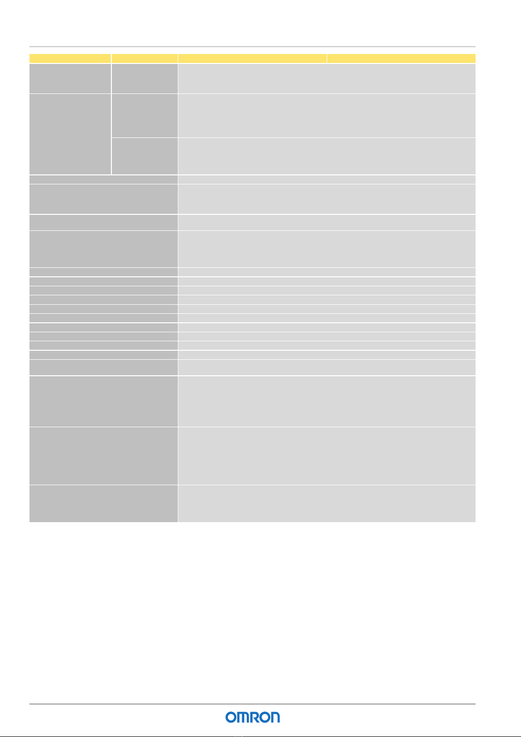
Model PNP output F3SJ-A____P14 F3SJ-A____P30
Input voltage PNP output Test input, interlock selection input, reset input, and muting input are all
ON voltage: 9 to 24 V (Vs) (sink current: 3 mA max.), OFF voltage: 0 to 1.5 V, or open
External device monitoring input
ON voltage: 9 to 24 V (Vs) (sink current: 5 mA max.), OFF voltage: 0 to 1.5 V, or open
Indicator Emitter Light intensity level indicators (green LED x 2, orange LED x 3): ON based on the light intensity
Error mode indicators (red LED x 3): Blink to indicate error details
Power indicator (green LED x 1): ON while power is on
Interlock indicator (yellow LED x 1): ON while under interlock, blinks at lockout.
External device monitoring indicator (muting input 1 indicator), Blanking/test indicator (muting input 2 indicator) (green LED x 2):
ON/flash according to function
Receiver Light intensity level indicators (green LED x 2, orange LED x 3): ON based on the light intensity
Error mode indicators (red LED x 3): Blink to indicate error details
OFF output indicator (red LED x 1): ON when safety output is OFF, blinks at lockout.
ON output indicator (green LED x 1): ON while safety output is ON
Muting error indicator, Blanking /test indicator (green LED x 2): ON/flash according to function
Mutual interference prevention function Interference light prevention algorithm, sensing distance change function
Series connection Time division emission by series connection
Number of connections: up to 4 sets
(F3SJ-A only) F3SJ-E, F3SJ-B and F3SJ-TS cannot be connected.
Total number of beams: up to 400 beams
Maximum cable length for 2 sets: no longer than 15 m
Test function Self test (at power-ON and at power distribution)
External test (emission stop function by test input)
Safety-related functions Start interlock, restart interlock (Must be set with a setting tool when the muting function is used.)
External device monitor
Muting (Lamp burnout detection, override function included. F39-CN6 key cap for muting is required.)
Fixed blanking (must be set by a setting tool)
Floating blanking (must be set by a setting tool)
Connection method Connector method (M12, 8-pin)
Protection circuit Output short-circuit protection, and power supply reverse polarity protection
Ambient temperature Operating: -10 to 55°C (no icing), Storage: -30 to 70°C
Ambient humidity Operating: 35% to 85% (no condensation), Storage: 35% to 95%
Operating ambient light intensity Incandescent lamp: receiving-surface light intensity of 3,000 lx max., Sunlight: receiving-surface light intensity of 10,000 lx max.
Insulation resistance 20 Mmin. (at 500 VDC)
Withstand voltage 1,000 VAC 50/60 Hz, 1 min
Degree of protection IP65 (IEC 60529)
Vibration resistance Malfunction: 10 to 55 Hz, Multiple amplitude of 0.7 mm, 20 sweeps in X, Y, and Z directions
Shock resistance Malfunction: 100 m/s2, 1,000 times each in X, Y, and Z directions
Material Casing (including metal parts on both ends): Aluminum, zinc die-cast
Cap: ABS resin, Optical cover: PMMA resin (acrylic), Cable: Oil resistant PVC
Weight (packaged) Calculate using the following expressions:
(1) For F3SJ-A____14, weight (g) = (protective height) x 1.7 +
(2) F3SJ-A____30, weight (g) = (protective height) x 1.5 +
The values for are as follows:
Protected height 245 to 596 mm: = 1,100 protected height 1,660 to 2,180 mm: = 2,400
Protected height 600 to 1,130 mm: = 1,500 protected height 2,195 to 2,500 mm: = 2,600
Protected height 1,136 to 1,658 mm: = 2,000
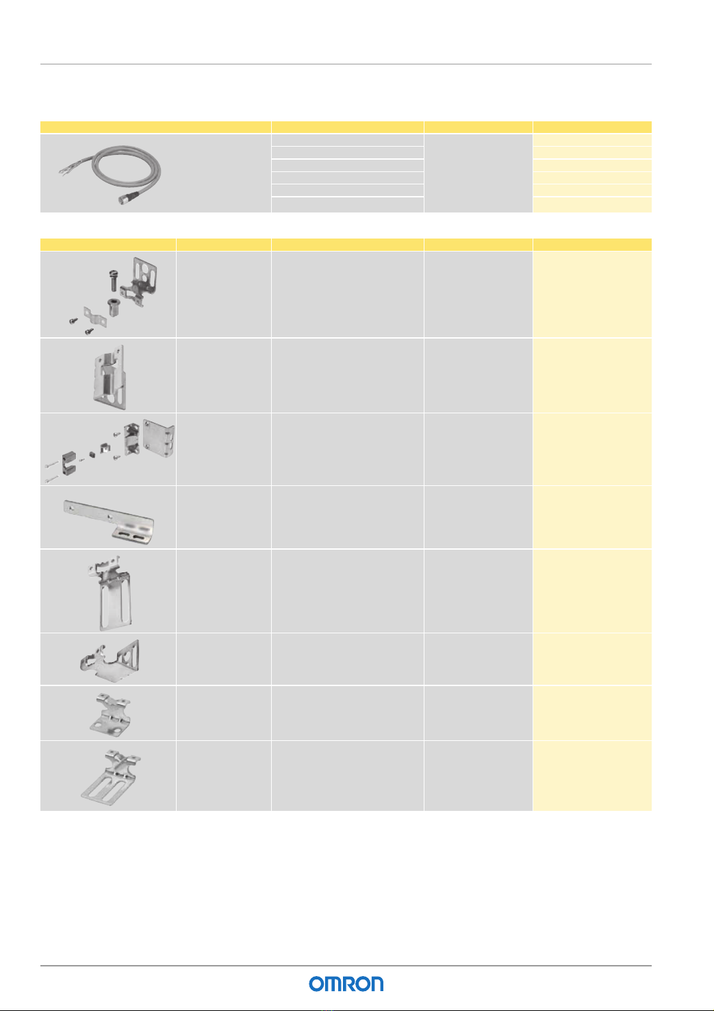
Accessories Test rod (*1), instruction manual, standard mounting bracket (F39-LJ1 bracket for top/bottom mounting), mounting brackets
(intermediate) (*2), error mode label, User's Manual (CD-ROM)
*1. The F3SJ-A@@@@55 is not included.
*2. Number of intermediate brackets depends on protective height of F3SJ.
For protective height from 600 to 1,130 mm: 1 set for each of the emitter and receiver is included
For protective height from 1,136 to 1,658 mm: 2 sets for each of the emitter and receiver are included
For protective height from 1,660 to 2,180 mm: 3 sets for each of the emitter and receiver are included
For protective height from 2,195 to 2,500 mm: 4 sets for each of the emitter and receiver are included
Applicable standards IEC 61496-1, EN 61496-1 UL 61496-1, Type 4 ESPE (Electro-Sensitive Protective Equipment)
IEC 61496-2, CLC/TS 61496-2, UL 61496-2, Type 4 AOPD (Active Opto-electronic Protective Devices)
IEC 61508-1 to -3, EN 61508-1 to -3 SIL3
IEC 13849-1: 2006, EN ISO 13849-1: 2008 (PLe, Cat.4)
UL 508, UL 1998, CAN/CSA C22.2 No.14, CAN/CSA C22.2 No.0.8

F3SJ-A Safety sensors
443
19 Safety sensors
Response Time
Note: Use the following expressions for series connection.
– For 2-set series connection:
Response time (ON to OFF): Response time of the 1st unit + Response time of the 2nd unit - 1 (ms), Response time (OFF to ON): Response time calculated by the above x 4 (ms)
– For 3-set series connection:
Response time (ON to OFF):
Response time of the 1st unit + Response time of the 2nd unit + Response time of 3rd unit - 5 (ms), Response time (OFF to ON): Response time calculated by the above x 5 (ms)
For models with the "-TS" suffix, multiply the response time obtained by the above x 5 (ms), or use 200 ms, whichever is less.)
– For 4-set series connection:
Response time (ON to OFF): Response time of the 1st unit + Response time of the 2nd unit + Response time of the 3rd unit + Response time of the 4th unit - 8 (ms)
Response time (OFF to ON): Response time calculated by the above x 5 (ms)
Cable Extension Length
Total cable extension length must be no greater than the lengths described below.
When the F3SJ and an external power supply are directly connected, or when the F3SJ is connected to a G9SA-300-SC.
When connected to the F3SP-B1P
Note: Keep the cable length within the rated length. Failure to do so is dangerous as it may prevent safety functions from operating normally.
Model Protected Height (mm) Number of Beams
Response time ms (ON to OFF)
Response time ms (OFF to ON)
F3SJ-A____14 Series 245 to 263 26 to 28 11 44
281 to 389 30 to 42 12 48
407 to 497 44 to 54 13 52
515 to 605 56 to 66 14 56
623 to 731 68 to 80 15 60
767 to 983 84 to 108 17.5 70
1,055 to 1,271 116 to 140 20 80
1,343 to 1,559 148 to 172 22.5 90
1,631 180 25 100
F3SJ-A____30 Series 245 to 395 10 to 16 10 40
420 to 720 17 to 29 11 44
745 to 1,045 30 to 42 12 48
1,070 to 1,295 43 to 52 13 52
1,395 to 1,620 56 to 65 14 56
1,745 to 1,995 70 to 80 15 60
2,120 to 2,495 85 to 100 17.5 70
Condition 1 set 2 sets 3 sets 4 sets
Using incandescent lamp for auxiliary output and external
indicator output
45 m 40 m 30 m 20 m
Not using incandescent lamp 100 m 60 m 45 m 30 m
Condition 1 set 2 sets 3 sets 4 sets
Using incandescent lamp for external indicator output 2 40 m 30 m 25 m 20 m
Using incandescent lamp for external indicator output 1 60 m 45 m 30 m 20 m
Using incandescent lamp for auxiliary output 1
Not using incandescent lamp 100 m 60 m 45 m 30 m

F3SJ-A Safety sensors
444
Accessories
Control Unit
Laser Pointer
Item Model F3SP-B1P
Applicable sensor F3SJ-B/A (Only for PNP output type)*1
*1 NPN output type cannot be connected. Also, the system cannot be used as a muting system.
Power supply voltage 24 VDC±10%
Power consumption DC1.7 W max. (not including sensor's current consumption)
Operation time 100 ms max. (not including sensor's response time)
Response time 10 ms max. (not including sensor's response time)
Relay output Number of contacts 3NO+1NC
Rated load 250 VAC 5 A (cos = 1), 30 VDC 5 A L/R = 0 ms
Rated current 5 A
Connection type Between sensors M12 connector (8-pin)
Others Terminal block
Weight (packed state) Approx. 280 g
Accessories Instruction manual
Item F39-PTJ
Applicable sensor F3SJ Series
Power supply voltage 4.65 or 4.5 VDC
Battery Three button batteries (SR44 or LR44)
Battery life*1
*1 Battery life varies depending on a battery used.
SR44: 10 hours of continuous operation, LR44: 6 hours of continuous operation
Light source Red semiconductor laser (wavelength: 650 nm, 1 mW max. JIS class 2, EN/IEC class 2, FDA class II)
Spot diameter (typical value) 6.5 mm at 10 m
Ambient temperature Operating: 0 to 40°C Storage: -15 to 60°C (with no icing or condensation)
Ambient humidity Operating and storage: 35% to 85% (with no condensation)
Material Laser module case: aluminum Mounting bracket: aluminum and stainless
Weight Approx. 220 g (packed)
Accessories Laser safety standard labels (EN: 1, FDA: 3) Button batteries (SR44: 3), instruction manual

F3SJ-A Safety sensors
445
19 Safety sensors
Connections
Basic Wiring Diagram
PNP Output
Wiring when using manual reset mode, external device monitoring.
Input/Output Circuit Diagram
Entire Circuit Diagram
PNP Output
The numbers in circles indicate the connectors' pin numbers. The black circles indicate connectors for series connection.
The words in brackets ([ ]) indicate the signal name for muting system.
*1 Open or muting input 1 for models with the "-TS" suffix.
*2 Open or muting input 2 for models with the "-TS" suffix.
S1 S2
K2
K1
KM2
KM1
KM1 KM2
0 V
+24 VDC
*1. Use a switch for small loads (input specifications: 24 V, 1.8 mA).
*2. F3SJ operates even when K1 and K2 are not connected.
S1 : External test switch (connect to 0 V if a switch is not required)
S2 : Interlock/lockout reset switch
KM1, KM2 : Safety relay with force-guided contact (G7SA) or magnetic
contactor
K1, K2 : Load or PLC, etc. (for monitoring)
Auxiliary output 2 (Red)
Test input (Green)
Auxiliary output 1
(Yellow)
Safety output 1
(Green)
Power
supply
*2
*2
*1*1
Receiver
Emitter
Shield
Reset input (Yellow)
Shield
Interlock select input (White)
External device
monitoring input (Red)
0 V (Blue)
0 V (Blue)
(Gray) Communication line (+)
(Pink)
Communication
line (−)
+24 V (Brown)
+24 V (Brown)
Safety output 2
(White)
S1
*1*1
*2
S3
K2
S1 : External test switch
(connect to 0 V if a switch is not required)
S3 : Lockout reset switch
(connect to 24 V if a switch is not required)
K2 : Load or PLC, etc. (for monitoring)
Auxiliary output 2 (Red)
Test input (Green)
Emitter
Reset input (Yellow)
Shield
Interlock select input (White)
0 V (Blue)
+24 V (Brown)
0 V
+24 VDC
Power
supply
(Gray) Communication line (+)
(Pink) Communication line (−)
*1. Use a switch for small loads
(Input specifications: 24 V, 1.8 mA).
*2. F3SJ operates even when K2 is not connected.
KM1
KM2
K1
KM1, KM2 : Safety relay with force-guided contact (G7SA)
or magnetic contactor
K1 : Load or PLC, etc. (for monitoring)
*F3SJ can operate even if K1 is not connected.
If K1 is not required, connect auxiliary output 1
to external device monitoring input only.
*
Shield
0 V (Blue)
+24 V (Brown)
0 V
+24 VDC
Power
supply
(Gray)
Communication line (+)
(Pink)
Communication line (−)
Auxiliary output 1
(Yellow)
Safety output 1 (Green)
External device
monitoring input (Red)
Safety output 2 (White)
Receiver
Wiring when the external device monitoring function
will not be used
• Use a setting tool to set the external device monitoring
function to "Disabled."
• When using an auxiliary output 1 that has not been changed
(output operation mode is "control output data," and inverse
of safety output signals is "Enabled), the external device
monitoring function will be disabled when auxiliary output 1
and the external device monitoring input are connected as
shown below.
Wiring for auto reset mode
• The auto reset mode will be enabled when the
emitter is wired as shown below.
Shield
Shield
Emitter
Main Circuit
Indicator
Indicator
Receiver
Main Circuit 2
Receiver
Main Circuit 1
+24 VDCBrown
Brown
Green Test input
White Interlock selection input
[Muting input 1] *1
Red
Auxiliary output 2
[Muting input 2] *2
Reset input
Yellow
Blue
Blue
Brown
Blue
Brown
Auxiliary output 1
Yellow
Green Safety output 1
Red External device
monitoring input
White Safety output 2
Blue
Load
Load
0 V
Communication line (−)
Pink
Gray
Gray Pink
Communication line (+)
Load
External indicator output 1
External indicator output 2
2
8
1
2
3
1
4
7
8
5
56
6
3
4
7

F3SJ-A Safety sensors
446
Connection Circuit Examples
Wiring for single F3SJ application (Category 4 acc. EN 954-1 and PLe acc. EN ISO 13849-1)
PNP Output
• Use of relay contact welding detection and interlock is possible without a controller or relay unit
*Auxiliary output 1 gives inverted signal of safety output (default setting).
S1
S2
KM1
KM2
OUT
PLC
IN M
KM2
KM1
KM3
KM2KM1
Auxiliary output 2 (Red)
Interlock selection input (White)
Unblocked
Blocked
External test switch (S1)
Reset switch (S2)
Safety output
KM1,KM2 N.O. contact
KM1,KM2 N.C. contact
PLC input *
PLC output
- Manual reset mode
- Using external device monitoring function
S1 : External test switch
(connect to 0 V if a switch is not required)
S2 : Interlock/lockout reset switch
KM, KM2 : Safety relay with force-guided contact (G7SA)
or magnetic contactor
K1 : Load, PLC (for monitor)
KM3 : Solid state contactor (G3J)
M : 3-phase motor
PLC : Programmable controller
(Used for monitoring -- not related to safety system)
K1
0 V
+24 VDC
Test input (Green)
Auxiliary output 1 (Yellow)
Safety output 1
(Green)
Power
supply
Receiver
Emitter
Shield
Reset input (Yellow)
Shield
External device
monitoring input (Red)
0 V (Blue)
0 V (Blue)
(Gray)
Communication line (+)
(Pink)
Communication
line (-)
+24 V (Brown)
+24 V (Brown)
Safety output 2
(White)
F39-JC@A-L F39-JC@A-D
Other manuals for F3SJ-A series
2
Table of contents
Other Omron Accessories manuals

Omron
Omron ZX-E - User manual

Omron
Omron ZW-C1*AT User manual

Omron
Omron F3S-TGR-SB-K C User manual

Omron
Omron ES1B User manual

Omron
Omron F210 User guide

Omron
Omron ZW-8000 Series User manual

Omron
Omron LASER ZX - User manual

Omron
Omron E3FS-10B4 2M User manual

Omron
Omron E8F2 - User manual

Omron
Omron E3MC - User manual

Omron
Omron E3ZM-C - User manual

Omron
Omron ZX-GT - User manual

Omron
Omron E2 ELITE User manual

Omron
Omron ZFX-C10 COMMUNICATION Operating manual

Omron
Omron E2A3 - User manual

Omron
Omron ZFV-SC10 Series User manual

Omron
Omron F500 - User manual

Omron
Omron E3F3 User manual

Omron
Omron fz5 series User guide

Omron
Omron ZFV-CA50 User manual