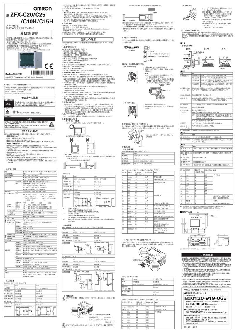
Omron FZ2 Series User manual

Cat. No. Z275-E1-01
FZ2 Series
Vision Sensors
USER'S MANUAL

FZ2 Series User's Manual
Vision Sensor
Rev.A
How This Manual Is Organized
This Manual includes two manuals, "User's Manual", which describes the basic
operations and settings of vision sensors, and "Processing Item List Manual", which
describes the setting options of each processing item.
Conventions Used in This Manual
Symbols
The symbols used in this manual have the following meanings.
Indicates the relevant operational precautions that must be
followed.
Indicates operation-related suggestions from OMRON.
Punctuation Marks
In this manual, Menu, among others, is defined as follows.
[ ] Menu indicates the name of menu or Processing item shown in the menu bar.
" " Item name indicates the item name displayed in the screen.

User's Manual
This manual describes the basic operations and all settings when using vision sensors.
This Manual includes two parts: Operation and Environment Settingas Parts. The
contents are shown as follows.
Operation Part
This part describes how to measure according to the workflow chapter by chapter.
First, prepare to measure by performing "Preparation"g"Design Contents to be
Measurement"g"Set up Contents to be Measurement".
Then, confirm whether or not to measure exactly against the expected objectives by
performing "Measurement Test"g"Adjusting Measurement Contents" repeatly.
Finally, perform "Actual Measurement"g"Verify Measurement Results".
In addition, this part also describes the operations of controller and how to utilize and
analyze the measurement results.
Environment Setting Part
This part describes the measurement environment (camera and lighting, etc.) and the
required system setting and configuration to facilitate the measurement.
In addition, this part also describes the required setting for outputting the measurement
results to external devices and how to store data.
For the Q&A and how to treat the encountered faults, see Appendix. Please read as
required.

User's Manual
Operation Part
Operation Part
This part describes the operation flow from planning to actual measurement and result
verification.
Before Operation
Design
Preparation
Setting up Scene (Measurement Flow)
Test Measurement/Re-measurement/Adjustment
Starting Operation
Utilizing/Analyzing Measured Data

Chapter 1 - Before Operation
This chapter describes fundamental operations and designations of components of this
product.
Operation Flow
Screens/Windows
Input Operation
Inputting a Value
Inputting a Text
Selecting Files and Folders
Operations of ProcItem Setting Window
Setting Figures
Saving Settings and Powering Off

Operation Flow
Here describes the operation flow.

Screens/Windows
The screen varies with the operating state. Some typical interface structures and various
buttons are functionally described hereto.

Main Screen (ADJUST window)
The screen is used for carrying out measurement, from which measurement results can be
verified.
1. Menu bar
To select the menu used for measurement-related operation or setting.
Main Screen Menu
2. "Measurement information display" area
1. Overall judgement
Displays the result of the overall judgement of a scene ([OK]/[NG]).
The judgement result for each processing item is displayed in each flow
unit of the "Control" area.
2. Process time

Displays the time required for the measurement process.
3. Status display
Displays the scene group number, the scene number, the external output
status, and the image mode for the currently displayed content.
3. Toolbar
Some common functions are reserved in Toolbar.
oEdit flow
Displays the Edit Flow window. In the displayed window, you can add,
delete, or edit processing units.
What is Scene
Edit Flow Window
oData save
Setting data is saved into flash memory in the controller. Scene group data
can also be saved to USB memory. Modified settings must be saved.
Saving Setting Data in the Controller's Memory [Data save]
oScene switch
To switch a scene group or a scene.
Changing Steps (Scene Switch)
oMeasure/Stop meas.
Starts/stops measurement. The measurement is performed in accordance
with [Test measurement] settings in the "Control" area.
Test Measurement before Actual Operation
oSwitch to RUN mode
Switches the display to the RUN window.
Edit Flow Window
4. "Image display" area

Displays the measured image.
1. ProcItem setting button
Displays the name of the processing item for the currently selected
processing unit. When tapping the button, the ProcItem Setting window is
displayed.
5. "Control" area
Displays "Test measurement setting", "Flow", "Detail result", and "Image view
setting". You can expand or collapse each item by tapping its panel.
oTest measurement setting
Sets up test measurement or re-measurement using a previously input
image.
Test Measurement before Actual Operation
oFlow

Displays the measurement flow for the scene used for measurement. Tap a
button for each unit to display the ProcItem Setting window and change
the processing unit settings.
Operations of ProcItem Setting Window
The size of the processing unit buttons can be switched by tapping
[Display] - [Display the enlarged measurement flow].
oDetail result
Displays with the text, detailed measurement results of the processing
units selected in the measurement flow.
oImage view setting
Specifies the display settings for the "Image display" area. Image
Display Setting
6. Measurement Manager bar
1. [Capture]
Saves the content displayed on the monitor as an image.
For settings and operation of [Capture], see Setting the Destination to
Save Capture Image [Screen capture setting].
2. [LCD Off]
Turns off the power of the LCD monitor. For settings and operation of
[LCD Off], see Powering Off LCD.

Main Screen (RUN window)
This is the window used during operation.
1. "Measurement information display" area
1. Overall judgement
Displays the result of the overall judgement of a scene ([OK]/[NG]).
The judgement result for each processing item is displayed in each flow
unit of the "Control" area.
2. Disp mode
The current image mode, [Through], [Freeze], or [Last NG], is displayed.
3. Scene group name and Scene name

Displays the scene group number and the scene number.
2. "Image display" area
Displays the measured image.
1. ProcItem setting button
Displays the name of the processing item for the currently selected
processing unit. If this button is tapped during simplified non-stop
adjustment, the ProcItem Setting window is displayed.
3. "Control" area
Displays "Flow", "Detail result", "Image view setting", and "Adjustment". You
can expand or collapse each item by tapping its panel.
oFlow
Displays the measurement flow for the scene used for measurement. When
a simple non-stop adjustment is executed, if you tap a button (icon) of
each unit (icon), judgement conditions are displayed in of the ProcItem

Setting window, and the settings can be changed.
Changing Judgement Condition of a Unit during Measurement
Important
oWhen simplified non-stop adjustment is not being performed, the
ProcItem Setting window is not displayed even if a button for a processing
unit is tapped.
In the RUN window, the size of processing unit buttons cannot be changed. To
change the size of processing unit buttons of the RUN window, set the size of
buttons in the ADJUST window, select "Data save", and then switch back to the
RUN window.
oDetail result
Displays with the text, detailed measurement results of the processing
units selected in the measurement flow.
oImage view setting
Specifies the display settings for the "Image display" area. Image Display
Setting
oAdjustment
Starts and stops simplified non-stop adjustment, and switches to the
ADJUST window.
4. Measurement Manager bar
1. [Capture]
Saves the content displayed on the monitor as an image.
For settings and operation of [Capture], see Setting the Destination to
Save Capture Image [Screen capture setting].
2. [LCD Off]
Turns off the power of the LCD monitor. For settings and operation of
[LCD Off], see Powering Off LCD.

ProcItem Setting Window
This window is used to set the Measurement parameters and judgement conditions, etc,
of Processing Item. For window operations, see Operations of ProcItem Setting
Window.
1. "Item tab" area
Displays detailed setting items as tabs, for the processing unit selected in the Edit
Flow window or in [Flow] of the "Control" area on the Main screen.
2. "Detail" area
Displays and changes settings for the detailed setting item selected in the "Item
tab" area.
3. "Image display" area
To display the Coordinate, figure and images captured from camera, etc.
4. "Zoom browser" area

Zooms in and out of the displayed image.
Using Zoom Function
3D Processing Item Window
1. "Image display" area
Displays the coordinates, figures and images captured from cameras, etc.
2. 3D camera switching button
When tapping the button, the camera image in the "Image display" area is
switched.
The button number indicates the camera image currently displayed in the "Image
display" area.
Depending on the camera used, the buttons will change as described below.
Table: 3D camera switching button
Camera number Buttons displayed
When using camera input 0 and 1. and are switched.

When using camera input 2 and 3. and are switched.
When using camera input 0, 1, and 2. ,and are switched in order.
Example) A display when camera input 0 and 1 are used.
Tapping switches it to , and the image of camera input 1 is displayed in
the "Image display" area.
Tapping switches it to , and the image of camera input 0 is displayed in
the "Image display" area.
3. "Sub image" Area
A camera image other than the image displayed in the "Image display" area is
displayed.

Setting Expression Window
This window is used for setting expressions for measurement. For the contents and
operation of this window, see Processing Items List Manual, "How to Display Setting
Expression Window".

Input Operation
This section describes the basic operations of input devices of this product.

Operations of Touch Pen (for Users of Panel-type Controller)
The touch pen is used in the touch screen in either of the following ways.
Tapping
Touch the screen slightly with the touch pen, and then take off immediately in order to
select
Processing items.
Drag & Drop
Draw while tapping the screen slightly with the touch pen.
Important
For touch screen operation, the supplied touch pen must be used. Otherwise, the
touch screen would be damaged when using a pencil or a ballpoint pen.
In addition, delay may occur when tapping touch screen continuously and rapidly.
This manual suits for next models
2
Table of contents
Other Omron Accessories manuals

Omron
Omron fh series User manual

Omron
Omron E3X-DACLRX1P-M3J 0.3M User manual

Omron
Omron LASER ZX - User manual

Omron
Omron ZX-E Series User manual

Omron
Omron E2A - User manual

Omron
Omron F3M-S Series User manual

Omron
Omron LASER ZX - User manual

Omron
Omron ZG - User manual

Omron
Omron E3G-L1 User manual

Omron
Omron F400 - 06-1999 User manual

Omron
Omron F210 User manual
Omron
Omron E3X-DAC-S Series User manual

Omron
Omron E3ZM-V61 User manual

Omron
Omron E32 - User manual

Omron
Omron ZX-T - User manual

Omron
Omron ZS User manual

Omron
Omron F160 Vision Sensor User manual

Omron
Omron E3MC - User manual

Omron
Omron E2F-X1R5Y1 User manual

Omron
Omron E2C-CR5B User manual