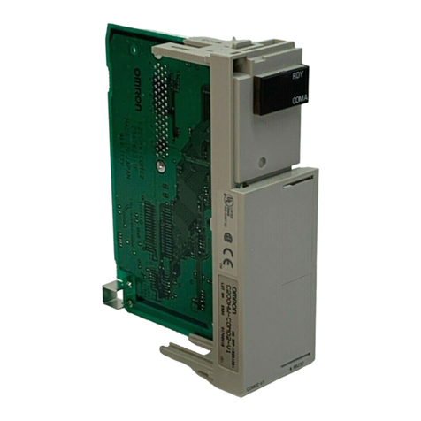
Omron C200HW-CORT21-V1 User manual

C200HW-CORT21-V1
CANopen Slave Unit
OPERATION MANUAL
OMRON
Cat. No. W904-E2-2


C200HW-CORT21-V1
CANopen Slave Unit
Operation Manual
Produced June 2001

iv

v
Notice:
OMRON products are manufactured for use according to proper procedures by a qualified operator
and only for the purposes described in this manual.
The following conventions are used to indicate and classify precautions in this manual. Always heed
the information provided with them. Failure to heed precautions can result in injury to people or
damage to the product.
Indicates information that, if not heeded, is likely to result in loss of life or serious injury.
Indicates information that, if not heeded, could possibly result in loss of life or serious
injury.
Indicates information that, if not heeded, could result in relatively serious or minor injury,
damage to the product, or faulty operation.
OMRON Product References
All OMRON products are capitalized in this manual. The word “Unit” is also capitalized when it refers
to an OMRON product, regardless of whether or not it appears in the proper name of the product.
The abbreviation “Ch,” which appears in some displays and on some OMRON products, often means
“word” and is abbreviated “Wd” in documentation in this sense.
The abbreviation “PLC” means Programmable Controller and is not used as an abbreviation for
anything else.
Visual Aids
The following headings appear in the left column of the manual to help you locate different types of
information. Note Indicates information of particular interest for efficient and convenient operation
of the product.
1, 2, 3… 1. Indicates lists of one sort or another, such as procedures, checklists, etc.
OMRON, 2001
All rights reserved. No part of this publication may be reproduced, stored in a retrieval system, or transmitted, in any
form, or by any means, mechanical, electronic, photocopying, recording, or otherwise, without the prior written
permission of OMRON.
No patent liability is assumed with respect to the use of the information contained herein. Moreover, because OMRON is
constantly striving to improve its high-quality products, the information contained in this manual is subject to change
without notice. Every precaution has been taken in the preparation of this manual. Nevertheless, OMRON assumes no
responsibility for errors or omissions. Neither is any liability assumed for damages resulting from the use of the
information contained in this publication.
!Caution
!DANGER!
!WARNING

vi

vii
TABLE OF CONTENTS
PRECAUTIONS..........................................................................................xi
1 Intended Audience.....................................................................................................................................xii
2 General Precautions...................................................................................................................................xii
3 Safety Precautions.....................................................................................................................................xii
4 Operating Environment Precautions..........................................................................................................xii
5 Application Precautions ...........................................................................................................................xiii
6 EC Directives...........................................................................................................................................xiv
1 ABOUT CANOPEN..............................................................................1
1-1 Introduction..............................................................................................................................................................2
1-2 Device description ...................................................................................................................................................2
1-3 Communication........................................................................................................................................................7
1-4 Configuration files.................................................................................................................................................19
1-5 CANopen conformance .........................................................................................................................................20
2 SPECIFICATIONS AND PERFORMANCE ..................................21
2-1 Overall Specifications............................................................................................................................................22
2-2 Dimensions ............................................................................................................................................................24
2-3 Performance...........................................................................................................................................................25
3 INSTALLATION ................................................................................31
3-1 Physical layout of the Unit.....................................................................................................................................32
3-2 Mounting the C200HW-CORT21-V1 ...................................................................................................................35
3-3 Setting up a network ..............................................................................................................................................36
4 PLC INTERFACE ..............................................................................47
4-1 Input and Output Data............................................................................................................................................48
4-2 I/O Data mapping...................................................................................................................................................49
4-3 Control and Status area..........................................................................................................................................60
5 MESSAGE COMMUNICATION, IOWR / IORD..........................69
5-1 Message communication........................................................................................................................................70
5-2 IOWR / IORD........................................................................................................................................................70
5-3 Error log.................................................................................................................................................................72
5-4 Reading the error log .............................................................................................................................................74
5-5 Writing to the local object dictionary.....................................................................................................................75
5-6 Reading from the local object dictionary...............................................................................................................77
5-7 Transmitting a user defined CAN message............................................................................................................79
5-8 Receiving a user defined CAN message................................................................................................................80
6 ERROR HANDLING AND STATUS...............................................85
6-1 Introduction............................................................................................................................................................86
6-2 Emergency message...............................................................................................................................................87
6-3 Error Register, Predefined Error Field...................................................................................................................90
6-4 Fatal PLC error handling .......................................................................................................................................91
6-5 LEDs, 7-Segment Display .....................................................................................................................................92
6-6 Flow diagrams........................................................................................................................................................93
7 TROUBLESHOOTING AND MAINTENANCE............................97
7-1 Error Indicators......................................................................................................................................................98
7-2 Troubleshooting.....................................................................................................................................................98
7-3 Maintenance.........................................................................................................................................................104
viii
Appendices
Appendix A EDS-file C200HW-CORT21-V1.......................................................................................107
Appendix B Stored Parameters...............................................................................................................113
Appendix C CS1 PLC series compatibility.............................................................................................115
Appendix D Baud rate configuration via Unit settings...........................................................................117
Index..........................................................................................................119
Revision History.......................................................................................123

ix
About this Manual:
This manual describes the installation and operation of the C200HW-CORT21-V1 CANopen Slave Unit
and includes the sections described below.
Please read this manual carefully and be sure you understand the information provided before
attempting to install and operate the CANopen Slave Unit. Be sure to read the precautions provided
in the following section.
Section 1 gives a brief description of CANopen.
Section 2 describes the overall specifications and the communication performance of the Unit.
Section 3 describes the installation of the C200HW-CORT21-V1.
Section 4 describes the interface with the user via the PLC system.
Section 5 describes the message communication.
Section 6 gives an overview of the implemented error handling and status mechanisms.
Section 7 describes the troubleshooting procedures and maintenance operations.
Failure to read and understand the information provided in this manual may result
in personal injury or death, damage to the product, or product failure. Please read
each section in its entirety and be sure you understand the information provided in
the section and related sections before attempting any of the procedures or
operations given.
!WARNING

x

xi
PRECAUTIONS
This section provides general precautions for using the CANopen Slave Units, Programmable Controllers, and related
devices.
The information contained in this section is important for the safe and reliable application of the CANopen Slave
Units. You must read this section and understand the information contained before attempting to set up or
operate a CANopen Slave Unit and PLC system.
1 Intended Audience.....................................................................................................................................xii
2 General Precautions...................................................................................................................................xii
3 Safety Precautions.....................................................................................................................................xii
4 Operating Environment Precautions..........................................................................................................xii
5 Application Precautions ...........................................................................................................................xiii
6 EC Directives...........................................................................................................................................xiv

Operating Environment Precautions Section 4
xii
1 Intended Audience
This manual is intended for the following personnel, who must also have
knowledge of electrical systems (an electrical engineer or the equivalent).
•Personnel in charge of installing FA systems.
•Personnel in charge of designing FA systems.
•Personnel in charge of managing FA systems and facilities.
2 General Precautions
The user must operate the product according to the performance
specifications described in the operation manuals.
Before using the product under conditions which are not described in the
manual or applying the product to nuclear control systems, railroad systems,
aviation systems, vehicles, combustion systems, medical equipment,
amusement machines, safety equipment, and other systems, machines, and
equipment that may have a serious influence on lives and property if used
improperly, consult your OMRON representative.
Make sure that the ratings and performance characteristics of the product are
sufficient for the systems, machines, and equipment, and be sure to provide
the systems, machines, and equipment with double safety mechanisms.
This manual provides information for installing and operating OMRON
CANopen Slave Units. Be sure to read this manual before operation and
keep this manual close at hand for reference during operation.
It is extremely important that a PLC and all PLC Units be used for the
specified purpose and under the specified conditions, especially in
applications that can directly or indirectly affect human life. You must consult
with your OMRON representative before applying a PLC system to the above
mentioned applications.
3 Safety Precautions
Never attempt to disassemble any Units while power is being supplied. Doing
so may result in serious electrical shock or electrocution.
Never touch any of the terminals while power is being supplied. Doing so
may result in serious electrical shock or electrocution.
4 Operating Environment Precautions
Do not operate the control system in the following places.
•Where the PLC is exposed to direct sunlight.
•Where the ambient temperature is below 0°C or over 55°C.
•Where the PLC may be affected by condensation due to radical
temperature changes.
•Where the ambient humidity is below 10% or over 90%.
•Where there is any corrosive or inflammable gas.
•Where there is excessive dust, saline air, or metal powder.
•Where the PLC is affected by vibration or shock.
•Where any water, oil, or chemical may splash on the PLC.
!WARNING
!WARNING
!WARNING

Application Precautions Section 5
xiii
The operating environment of the PLC System can have a large effect on the
longevity and reliability of the system. Improper operating environments can
lead to malfunction, failure, and other unforeseeable problems with the PLC
System. Be sure that the operating environment is within the specified
conditions at installation and remains within the specified conditions during
the life of the system.
5 Application Precautions
Observe the following precautions when using the CANopen Salve Units or
the PLC.
Failure to abide by the following precautions could lead to serious or possibly
fatal injury. Always heed these precautions.
•Always ground the system to 100 Ωor less when installing the system to
protect against electrical shock.
•Always turn OFF the power supply to the PLC before attempting any of the
following. Performing any of the following with the power supply turned ON
may lead to electrical shock:
•Mounting or removing any Units (e.g., I/O Units, CPU Unit, etc.) or
memory cassettes.
•Assembling any devices or racks.
•Connecting or disconnecting any cables or wiring.
Failure to abide by the following precautions could lead to faulty operation of
the PLC or the system or could damage the PLC or PLC Units. Always heed
these precautions.
•Use the Units only with the power supplies and voltages specified in the
operation manuals. Other power supplies and voltages may damage the
Units.
•Take measures to stabilise the power supply to conform to the rated supply
if it is not stable.
•Provide circuit breakers and other safety measures to provide protection
against shorts in external wiring.
•Do not apply voltages exceeding the rated input voltage to Input Units. The
Input Units may be destroyed.
•Do not apply voltages exceeding the maximum switching capacity to
Output Units. The Output Units may be destroyed.
•Always disconnect the LG terminal when performing withstand voltage
tests.
•Install all Units according to instructions in the operation manuals. Improper
installation may cause faulty operation.
•Provide proper shielding when installing in the following locations:
•Locations subject to static electricity or other sources of noise.
•Locations subject to strong electromagnetic fields.
•Locations subject to possible exposure to radiation.
•Locations near power supply lines.
•Be sure to tighten Backplane screws, terminal screws, and cable connector
screws securely.
•Do not attempt to take any Units apart, to repair any Units, or to modify any
Units in any way.
The following precautions are necessary to ensure the general safety of the
system. Always heed these precautions.
•Provide double safety mechanisms to handle incorrect signals that can be
generated by broken signal lines or momentary power interruptions.
!Caution
!Caution
!Caution
!WARNING

EC Directives Section 6
xiv
•Provide external interlock circuits, limit circuits, and other safety circuits in
addition to any provided within the PLC to ensure safety.
6 EC Directives
1,2,3…
1,2,3…
C200HW-CORT21-V1 Units that meet EC directives must be installed as
follows:
1. C200HW-CORT21-V1 Units are defined for installation inside control
panels. All C200HW-CORT21-V1 Units must be installed within control
panels.
2. Use reinforced insulation or double insulation for the DC power supplies
used for the communications power supply, internal circuit power supply,
and the I/O power supplies.
3. C200HW-CORT21-V1 Units that meet EC directives also meet the
common emission standard (EN50081-2). When C200HW-CORT21-V1
products are built into equipment, however, the measure necessary to
ensure that the standard is met will vary with the overall configuration of
the control panel, the other devices connected tot the control panel, and
other conditions. The user must therefore confirm that EC directives are
met for the overall machine or device.
The following examples show means of reducing noise.
1. Noise from the communications cable can be reduced by installing a
ferrite core on the communications cable within 10 cm of the C200HW-
CORT21-V1 Unit.
2. Wire the control panel with as thick and short electric lines as possible
and ground to 100 Ωor less.
3. Keep the communications cables as short as possible and ground to
100 Ωor less.

1
1About CANopen
This section gives a brief description of CANopen.
1-1 Introduction..............................................................................................................................................................2
1-2 Device description ...................................................................................................................................................2
1-2-1CANopen Reference Model...............................................................................................................................2
1-2-2Device model....................................................................................................................................................4
1-2-2-1 Object dictionary.........................................................................................................................................................4
1-2-2-2 Application Interface...................................................................................................................................................6
1-2-2-3 Communication Interface............................................................................................................................................7
1-3 Communication........................................................................................................................................................7
1-3-1Process Data Objects (PDOs)..........................................................................................................................7
1-3-1-1 Communication parameters.........................................................................................................................................8
1-3-1-2 Mapping parameters....................................................................................................................................................9
1-3-2Service Data Objects (SDOs) .........................................................................................................................10
1-3-3Special Function Objects................................................................................................................................11
1-3-3-1 SYNC Object ............................................................................................................................................................11
1-3-3-2 Time Stamp Object....................................................................................................................................................12
1-3-3-3 EMCY Object............................................................................................................................................................12
1-3-4Network Management Objects (NMT)............................................................................................................13
1-3-4-1 Module Control Services...........................................................................................................................................14
1-3-4-2 Error control services................................................................................................................................................15
1-3-4-3 Configuration control services ..................................................................................................................................15
1-3-5Predefined Connection Set .............................................................................................................................16
1-3-6Device configuration ......................................................................................................................................17
1-3-7Network length................................................................................................................................................18
1-4 Configuration files.................................................................................................................................................19
1-5 CANopen conformance .........................................................................................................................................20

Introduction Section 1-1
2
1-1 Introduction
Based on CAN
Application areas
CANopen Master vs. Slave
CANopen specifications
CANopen is a networking system based on the serial bus CAN (Controller
Area Network).
CANopen was developed within the scope of an 'ESPRIT' EU research
programs led by Robert Bosch GmbH (initial developer of CAN) at the end of
1993. It encompasses a subset of the higher layer protocol CAL (CAN
Application Layer), developed by Philips Medical Systems, and some extra
functionality to meet the application area.
CANopen was originally designed for motion-oriented industrial control
systems, such as handling systems. But CANopen networks are also used in
other application fields, e.g. public transportation, off-road vehicles, medical
equipment, maritime electronics, and building automation.
CANopen makes full use of the powerful features of CAN. It supports the
multi-master functionality, that enables (cyclic or event-driven)
communication between any two or more nodes, and it offers a lot of other
configuration flexibility. This flexibility makes this protocol a bit less plug-and-
play than other common protocols, but it gives the system integrator more
power in fine tuning the network.
In contrast with other industrial fieldbus systems, there is no clearly defined
separation between the functionality of CANopen master- and slave devices.
This means that in practise there will be many different types of CANopen
Master devices and slave devices, each with their own specific level of
functionality.
This chapter only gives a brief description of CANopen; please refer to the
CANopen specifications, issued by CAN in Automation, for more detailed
information.
1-2 Device description
A CANopen device is best described by its OSI reference model and its
device model.
1-2-1 CANopen Reference Model
The following figure depicts the reference model of a CANopen device.

Device description Section 1-2
3
OSI model
ISO 11898
Profiles
The model is according the ISO Open Systems Interconnection (OSI)
reference model. Of this seven-layer model, only three are applicable for a
CANopen device (the physical layer, the data link layer and the application
layer).
The data link layer and a part of the physical layer are described in ISO
11898, and are usually implemented in silicon (CAN controller).
CANopen provides a standardised application layer and communication
profile. The optional framework for programmable devices specifies
additional communication functionality. In addition, CANopen specifies bit-
timing and recommends pin-assignments for several types of connector.
The standardised device profiles, interface profiles, and application profiles
describe the default behaviour and the optional functionality of devices,
interfaces, and applications.
The interaction between devices at the three ISO layers is depicted below.
At the application layer, the interaction involves the accessing of objects via
an index numbering system. Refer to section 1-2-2-1 for more details about
objects and indexing.
At the data link layer, these object accesses are translated to CAN message
frames with certain identifiers and data blocks. The maximum number of data
bytes per CAN frame is eight, therefore accesses to larger-sized objects in
the device are fragmented over more than one frame.
At the CAN physical layer, the CAN frames are translated to bus signal levels
and vice versa.
Table of contents
Other Omron Conference System manuals

Omron
Omron Sysmac E3X-ECT User manual

Omron
Omron GRT1-CRT - 05-2008 User manual

Omron
Omron V640 User manual

Omron
Omron SYSDRIVE MX2 SERIES User manual

Omron
Omron GRT1 - 27-11-2006 User manual

Omron
Omron SMARTSLICE - 04-2008 User manual

Omron
Omron DRT1-COM User manual

Omron
Omron V680 - 2 User manual

Omron
Omron ZS-CRT User manual

Omron
Omron V670 Series User manual