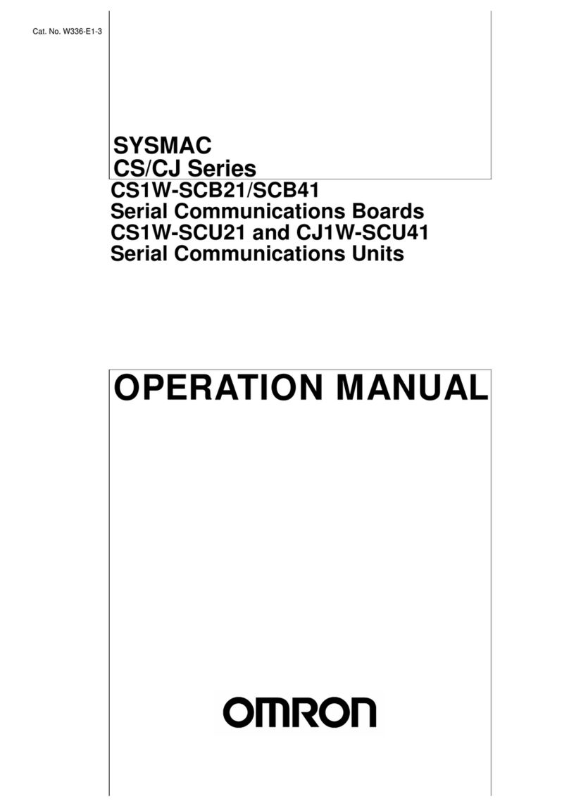
Omron GRT1-CRT - 05-2008 User manual

CompoNet Communications Unit
Cat. No. W476-E1-01
SmartSlice
GRT1-CRT
OPERATION MANUAL

SmartSlice
GRT1-CRT
CompoNet Communications Unit
Operation Manual
Produced May 2008

iv

Introduction
v
Introduction
Thank you for buying a SmartSlice CompoNet Communications Unit.
The CompoNet Communications Unit is an interface unit which complies with the CompoNet
standard. It connects SmartSlice I/O Units to a CompoNet Master Unit.
Be sure you understand the functions and performance of the Units fully before you use them.
Intended Audience
This manual is for the personnel below. This personnel must understand electrical systems (must
be an electrical engineer or the equivalent).
Personnel responsible for the selection of FA systems
Personnel responsible for the designs of FA systems
Personnel responsible for the installation of and connections in FA systems
Personnel responsible for the management of FA systems
Precaution
This manual contains data which is necessary for you to use a CompoNet Communications Unit.
Read and understand this manual fully before you use the CompoNet Communications Unit. After
you read this manual, keep it in a safe location where it will be available for use when necessary.
Be sure that the end user of the CompoNet Communications Unit has this manual.

Read and Understand this Manual
vi
Read and Understand this Manual
Please read and understand this manual before using the product. Please consult your OMRON
representative if you have any questions or comments.
Warranty and Limitations of Liability
WARRANTY
OMRON's exclusive warranty is that the products are free from defects in materials and workmanship
for a period of one year (or other period if specified) from date of sale by OMRON.
OMRON MAKES NO WARRANTY OR REPRESENTATION, EXPRESS OR IMPLIED, REGARDING
NON-INFRINGEMENT, MERCHANTABILITY, OR FITNESS FOR PARTICULAR PURPOSE OF THE
PRODUCTS. ANY BUYER OR USER ACKNOWLEDGES THAT THE BUYER OR USER ALONE HAS
DETERMINED THAT THE PRODUCTS WILL SUITABLY MEET THE REQUIREMENTS OF THEIR
INTENDED USE. OMRON DISCLAIMS ALL OTHER WARRANTIES, EXPRESS OR IMPLIED.
LIMITATIONS OF LIABILITY
OMRON SHALL NOT BE RESPONSIBLE FOR SPECIAL, INDIRECT, OR CONSEQUENTIAL
DAMAGES, LOSS OF PROFITS OR COMMERCIAL LOSS IN ANY WAY CONNECTED WITH THE
PRODUCTS, WHETHER SUCH CLAIM IS BASED ON CONTRACT, WARRANTY, NEGLIGENCE, OR
STRICT LIABILITY.
In no event shall the responsibility of OMRON for any act exceed the individual price of the product on
which liability is asserted.
IN NO EVENT SHALL OMRON BE RESPONSIBLE FOR WARRANTY, REPAIR, OR OTHER CLAIMS
REGARDING THE PRODUCTS UNLESS OMRON'S ANALYSIS CONFIRMS THAT THE PRODUCTS
WERE PROPERLY HANDLED, STORED, INSTALLED, AND MAINTAINED AND NOT SUBJECT TO
CONTAMINATION, ABUSE, MISUSE, OR INAPPROPRIATE MODIFICATION OR REPAIR.

Read and Understand this Manual
vii
Application Considerations
SUITABILITY FOR USE
OMRON shall not be responsible for conformity with any standards, codes, or regulations that apply to
the combination of products in the customer's application or use of the products.
At the customer's request, OMRON will provide applicable third party certification documents identifying
ratings and limitations of use that apply to the products. This information by itself is not sufficient for a
complete determination of the suitability of the products in combination with the end product, machine,
system, or other application or use.
The following are some examples of applications for which particular attention must be given. This is not
intended to be an exhaustive list of all possible uses of the products, nor is it intended to imply that the
uses listed may be suitable for the products:
• Outdoor use, uses involving potential chemical contamination or electrical interference, or conditions
or uses not described in this manual.
• Nuclear energy control systems, combustion systems, railroad systems, aviation systems, medical
equipment, amusement machines, vehicles, safety equipment, and installations subject to separate
industry or government regulations.
• Systems, machines, and equipment that could present a risk to life or property.
Please know and observe all prohibitions of use applicable to the products.
NEVER USE THE PRODUCTS FOR AN APPLICATION INVOLVING SERIOUS RISK TO LIFE OR
PROPERTY WITHOUT ENSURING THAT THE SYSTEM AS A WHOLE HAS BEEN DESIGNED TO
ADDRESS THE RISKS, AND THAT THE OMRON PRODUCTS ARE PROPERLY RATED AND
INSTALLED FOR THE INTENDED USE WITHIN THE OVERALL EQUIPMENT OR SYSTEM.

Read and Understand this Manual
viii
Disclaimers
CHANGE IN SPECIFICATIONS
Product specifications and accessories may be changed at any time based on improvements and other
reasons.
It is our practice to change model numbers when published ratings or features are changed, or when
significant construction changes are made. However, some specifications of the products may be
changed without any notice. When in doubt, special model numbers may be assigned to fix or establish
key specifications for your application on your request. Please consult with your OMRON representative
at any time to confirm actual specifications of purchased products.
DIMENSIONS AND WEIGHTS
Dimensions and weights are nominal and are not to be used for manufacturing purposes, even when
tolerances are shown.
PERFORMANCE DATA
Performance data given in this manual is provided as a guide for the user in determining suitability and
does not constitute a warranty. It may represent the result of OMRON's test conditions, and the users
must correlate it to actual application requirements. Actual performance is subject to the OMRON
Warranty and Limitations of Liability.
ERRORS AND OMISSIONS
The information in this manual has been carefully checked and is believed to be accurate; however, no
responsibility is assumed for clerical, typographical, or proofreading errors, or omissions.

Safety Precautions
ix
Safety Precautions
Safety Indications
The indications below are used in this manual for safety precautions which are necessary to use the
CompoNet Communications Unit safely. The contents of these safety precautions are important. Al-
ways obey them.
These are the indications for safety precautions.
• “Precautions for Safe Application” shows the operations that you must do or
not do to use the product safely.
• “Precautions for Correct Application” shows operations that you must do or not
do to make sure that the product operates, prevent malfunctions, and prevent
bad effects on performance and functions.
WARNING
Caution
Indicates a potentially hazardous situation which, if not
avoided, could result in death or serious injury.
Additionally, there may be severe property damage.
Indicates a potentially hazardous situation which, if not
avoided, may result in minor or moderate injury, or property
damage.
Precaution for
Safe Usage
Precaution for
Correct Usage

Safety Precautions
x
Descriptions of Symbols
This symbol shows operations that you must not do.
The specified operation shows in the circle.
This example shows “do not disassemble.”
This symbol shows precautions (including warnings).
The specified operation shows in the triangle.
This example shows a general precaution.
This symbol shows operations that you must do.
The specified operation shows in the circle.
This example shows a general precaution for something that
you must do.
WARNING
Do not try to disassemble a Unit or touch the terminal block while
the power is ON. Doing this can cause electrical shock.
Make sure that the voltage and current input to the Units are in the
specified ranges. If the voltage and current are not in the specified
ranges, there can be Unit malfunctions or fire.
Turn OFF the I/O power supply to a SmartSlice I/O Unit before you
replace it with the online replacement procedure. If there is external
power to a terminal for a Relay Output Slave, for example, turn OFF
the external power before you replace the SmartSlice I/O Unit. If
you replace a Slave I/O Unit with the power ON, incorrect outputs,
incorrect inputs, or electric shock can occur.

Safety Precautions
xi
Apply safety measures in external circuits (that is, not in the Smart-
Slice I/O Terminal) to keep safety in the system. These measures
must keep safety if a malfunction in the control system or other ex-
ternal factor which has an effect on the control system causes a
problem. Include the items below. Not doing this can cause serious
accidents.
• There must be emergency stop circuits, interlock circuits, limit cir-
cuits, and other safety measures in external control circuits.
• The SmartSlice outputs can stay ON or OFF because of welding
or burning of the output relays, or destruction of the output tran-
sistors. As a countermeasure for such errors, there must be ex-
ternal safety measures to keep safety in the system.
• The SmartSlice I/O Terminal will continue operating when one or
more I/O Units are missing from the SmartSlice I/O Terminal. The
other I/O Units will continue the control operations, including the
control of the outputs. As a countermeasure for such errors, there
must be external safety measures to keep safety in the system.
The CPU Unit refreshes I/O when the program is stopped in PRO-
GRAM mode. Fully make sure that it is safe before changing the
status of bits or words in memory allocated to Output Slaves, Spe-
cial I/O Units, or CPU Bus Units. If you change the bits or words al-
located to a Slave or Unit, you could cause incorrect operation of
the loads connected to the Slave or Unit. The operations below will
change memory status.
• Transferring I/O memory data to the CPU Unit from a Program-
ming Device
• Changing present values in memory from a Programming Device
• Force-setting or force-resetting bits from a Programming Device
• Transferring I/O memory files from a Memory Card or EM file
memory to the CPU Unit
• Transferring I/O memory from a host computer or from a PLC on
a network

Precautions for Safe Usage
xii
Precautions for Safe Usage
• Put a Unit in the special box during transportation. Make sure that the Unit is moved carefully, and
not given too much vibration or shock during transportation.
• Do not let a Unit fall or give it too much vibration or shock. This can cause malfunction or cause
damage to the Unit.
• Install the SmartSlice I/O Terminal correctly on DIN Track.
• Be sure that you correctly lock the terminal block, the communications cable connectors, and other
items with locking devices.
• Correctly connect the Units as this manual shows.
• Interference between the Flat Cables for more than one CompoNet System can cause operation
that is not stable. Keep the Flat Cables for different CompoNet Systems apart by a minimum of
5 mm. Interference can occur for Sheathed Cable or Unsheathed Cable.
• Do not let metal objects enter the Unit when connecting or installing it.
• Connect ferrules to the wires when you connect the wires. Do not connect stranded wires directly
to terminals.
• Use the specified communications cables and connectors.
• Use the correct polarity when connecting the terminals.
• Put the ferrules fully into the holes.
• Do a full check of the terminal block before you attach it.
• Do not bend the cables to more than their normal bending radius or pull on the cables.
• Obey the following precautions when connecting communications cables.
• Keep the communications cables away from the power lines or high-tension lines.
• Do not bend the communications cables with too much force.
• Do not pull on the communications cables with too much force.
• Do not put objects on the communications cables.
• Put the communications cables in ducts.
• If the power supply conditions are bad, install countermeasures to make sure that the power
supply always has the rated voltage.
• You must make interlock circuits, limit circuits, and other safety measures in circuits that are
external to the control system.
• Use the power supply voltage which this manual specifies.
• Make sure that there will be no problems when the Unit changes to fixed allocations for the I/O
Areas before you clear the Registration Table. (You set user remote I/O allocations in the
Registration Table.)
• Do not let the communications distance be higher than the specified value.
• Install circuit breakers and other safety measures to prevent Unit damage which short-circuits in
external wires can cause.
• Install failsafe measures to make sure that the system is safe if disconnected signal lines or short
power interruptions cause incorrect signals.
• Always obey the voltage specifications for power supply connections and I/O jumpers. Incorrect
connections can cause malfunctions.
• Do not apply a voltage or connect a load which is larger than the maximum switch capacity to an
Output Slave.
• Do not apply a voltage which is larger than the rated voltage to an Input Slave.
• Be sure there are no mistakes in connections or switch settings before you turn ON the power
supply.

Precautions for Safe Usage
xiii
• Be sure to turn OFF the power to the PLC and Slaves before doing these operations.
• Assembling a SmartSlice I/O Terminal
• Setting the rotary switches
• Connecting cables
• Be sure that there will be no bad effects on the system before doing these operations.
• Changing the operating mode of the CPU Unit
• Setting or resetting bits in memory
• Changing set values or present values on the user program
• Before touching a Unit, touch a grounded metal object to release static electricity from your body.
• When you replace a part, be sure that the specifications of the replacement part are correct.
• Do not try to disassemble, repair, or change a Unit.

Precautions for Correct Usage
xiv
Precautions for Correct Usage
Correctly install the Units as this manual shows.
Do not install the Units in these locations.
• Locations with direct sunlight
• Locations with temperatures or humidity not in the range specified in the specifications
• Locations with condensation as the result of large changes in temperature
• Locations with corrosive gases or flammable gases
• Locations with dust (specially iron dust) or salts
• Locations with water, acid, oil, or chemicals
• Locations with shock or vibration
Install applicable and sufficient countermeasures if you install the system in these locations.
• Locations with static electricity or other types of noise
• Locations with strong electromagnetic fields
• Locations with possible exposure to radioactivity
• Locations near power lines

EC Directives
xv
EC Directives
Applicable Directives
•EMCDirective
• Low Voltage Directive
Concepts
EMC Directive
The SmartSlice I/O Terminals are electrical devices which are installed in a machine in application.
The Terminals comply with the EMC Directive. This makes it easier for the machine in which a Ter-
minal is installed to more easily comply with the EMC directive. (See note.)
The EMC-related performance of the OMRON devices which comply with EC Directives changes
with the machine in which they are installed. This includes the configuration, connections, and other
conditions of the machine. The customer must do the checks to make sure that the devices and the
machine conform to EMC standards.
Note:
The applicable EMC (electro-magnetic compatibility) standards are EN 61131-2 and EN 61000-6-2
for EMS (electro-magnetic susceptibility) and EN 61131-2 and EN 61000-6-4 for electro-magnetic
interference. The 10-m regulations apply for radiated emissions.
Low Voltage Directive
Devices which operate at voltages from 50 to 1,000 VAC or 75 to 1,500 VDC must comply with the
related safety requirements. The applicable standard is EN 61131-2.
Complying with EC Directives
The SmartSlice I/O Units comply with EC Directives. These measures are necessary for the ma-
chine containing a SmartSlice I/O Units to comply with the EC Directives.
1. You must install the SmartSlice I/O Units in a control panel.
2. You must use reinforced insulation or double insulation for the DC power supplies used for the
Unit power supplies, and the I/O power supplies. Make sure that the outputs are stable if a 10-ms
interruption occurs at the input.
We recommend the S82J Power Supply which is made by OMRON. (See note.)
3. The SmartSlice I/O Units which conform to EC Directives conform to the EMI standards (EN
61131-2 (Immunity Zone A), EN 61000-6-2, and EN 61000-6-4). The radiated emission proper-
ties (10-m regulations) can change with the configuration of the control panel, other devices
which are connected to the control panel, connections, and other conditions.
You must make sure that the completed machine complies with EC Directives.
4. Compliance tests were done with I/O wires of a maximum length of 30 m.
Note:
Compliance tests for EMC standards were done with the recommended power supply.

Related Manuals
xvi
Related Manuals
This table shows the manuals which are related to the CompoNet Communications Unit. Read
these manuals together with this Manual.
Cat. No. Manual Contents
W476 (this
manual)
SmartSlice CompoNet
Communications Unit
Operation Manual
This manual tells you about the functions, specifications, and
operating procedures of the CompoNet Communications
Unit.
W455
GRT1 Series SmartSlice
I/O Units Operation Man-
ual
This manual tells you about the models, functions, specifica-
tions, and operating procedures of the SmartSlice I/O Units.
W456
CS/CJ Series CompoNet
Master Unit Operation
Manual
This manuals tells you about the CompoNet network, commu-
nications specifications, connection procedures, and the CS/
CJ-series CompoNet Master Unit.
W342
SYSMAC CS/CJ/CP Se-
ries and SYSMAC One
NSJ Series Communica-
tions Commands Refer-
ence Manual
This manual tells you about the communications commands
which you can use with the CS/CJ-series CompoNet Master
Unit.

About this Manual
xvii
About this Manual
Section Overview
Section 1 Features and System
Configuration
Section 1 tells you about the SmartSlice system. It also tells you
about the features, system configuration, and specifications of the
CompoNet Communications Unit.
Section 2 Nomenclature and
Functions
Section 2 tells you about the names and functions of the parts of the
CompoNet Communications Unit.
Section 3 Installing the Units Section 3 tells you how to install the CompoNet Communications
Unit and SmartSlice I/O Units.
Section 4 Connecting the Units Section 4 tells you how to connect the CompoNet Communications
Unit and SmartSlice I/O Units.
Section 5 Unit Settings and I/O
Allocations
Section 5 tells you how to set the unit address and unit number. It
also tells how to allocate I/O in the CompoNet Master Unit.
Section 6 Smart Functions Section 6 tells you about the many smart functions of the SmartSlice
system.
Section 7 Basic Operation Section 7 gives the procedures for and example of operating a
SmartSlice system.
Section 8 Remote I/O Commu-
nications
Section 8 tells you about the communications timing for remote I/O
communications and message communications. It also gives more
information on communications.
Section 9 Error Procedures
Section 9 tells you how to troubleshoot problems that you can have
with the CompoNet Communications Unit and SmartSlice I/O Units.
It also tells how to see the error history with the CX-Integrator.
Appendices
The appendices give an overview of explicit messages (for example,
to send commands) and a list of command functions. The appendi-
ces also give lists of related products.

About this Manual
xviii

xix
TABLE OF CONTENTS
SECTION 1
Features and System Configuration . . . . . . . . . . . . . . . . . . . 1
1-1 The SmartSlice I/O System . . . . . . . . . . . . . . . . . . . . . . . . . . . . . . . . . . . . . . . . . . . . . . . . . . 2
1-2 Features of the CompoNet SmartSlice I/O Terminals . . . . . . . . . . . . . . . . . . . . . . . . . . . . . . 3
1-3 System Configuration . . . . . . . . . . . . . . . . . . . . . . . . . . . . . . . . . . . . . . . . . . . . . . . . . . . . . . 5
1-4 Specifications. . . . . . . . . . . . . . . . . . . . . . . . . . . . . . . . . . . . . . . . . . . . . . . . . . . . . . . . . . . . . 7
SECTION 2
Nomenclature and Functions. . . . . . . . . . . . . . . . . . . . . . . . . 11
2-1 Nomenclature. . . . . . . . . . . . . . . . . . . . . . . . . . . . . . . . . . . . . . . . . . . . . . . . . . . . . . . . . . . . . 12
2-2 Indicators . . . . . . . . . . . . . . . . . . . . . . . . . . . . . . . . . . . . . . . . . . . . . . . . . . . . . . . . . . . . . . . . 14
2-3 Switches. . . . . . . . . . . . . . . . . . . . . . . . . . . . . . . . . . . . . . . . . . . . . . . . . . . . . . . . . . . . . . . . . 18
SECTION 3
Installing the Units . . . . . . . . . . . . . . . . . . . . . . . . . . . . . . . . . 21
3-1 Installing a SmartSlice I/O Terminal . . . . . . . . . . . . . . . . . . . . . . . . . . . . . . . . . . . . . . . . . . . 22
3-2 Installing the Turnback Units . . . . . . . . . . . . . . . . . . . . . . . . . . . . . . . . . . . . . . . . . . . . . . . .27
SECTION 4
Connecting the Units . . . . . . . . . . . . . . . . . . . . . . . . . . . . . . . 29
4-1 Connecting the Communications Cables. . . . . . . . . . . . . . . . . . . . . . . . . . . . . . . . . . . . . . . . 30
4-2 Connecting the Power Supply Cables . . . . . . . . . . . . . . . . . . . . . . . . . . . . . . . . . . . . . . . . . . 31
4-3 Connecting the Turnback Cables. . . . . . . . . . . . . . . . . . . . . . . . . . . . . . . . . . . . . . . . . . . . . . 35
4-4 Precautions When Connecting the Power Supplies. . . . . . . . . . . . . . . . . . . . . . . . . . . . . . . . 36
4-5 Connecting the Signal Lines for External Devices . . . . . . . . . . . . . . . . . . . . . . . . . . . . . . . . 38
SECTION 5
Unit Settings and I/O Allocations . . . . . . . . . . . . . . . . . . . . . 39
5-1 Setting the Node Addresses. . . . . . . . . . . . . . . . . . . . . . . . . . . . . . . . . . . . . . . . . . . . . . . . . .40
5-2 Unit Numbers for SmartSlice I/O Units . . . . . . . . . . . . . . . . . . . . . . . . . . . . . . . . . . . . . . . . 41
5-3 I/O Allocations to CompoNet Master Unit . . . . . . . . . . . . . . . . . . . . . . . . . . . . . . . . . . . . . . 42
SECTION 6
Smart Functions . . . . . . . . . . . . . . . . . . . . . . . . . . . . . . . . . . . 53
6-1 Overview of Smart Functions . . . . . . . . . . . . . . . . . . . . . . . . . . . . . . . . . . . . . . . . . . . . . . . . 54
6-2 Registration Table . . . . . . . . . . . . . . . . . . . . . . . . . . . . . . . . . . . . . . . . . . . . . . . . . . . . . . . . . 54
6-3 Backup Function . . . . . . . . . . . . . . . . . . . . . . . . . . . . . . . . . . . . . . . . . . . . . . . . . . . . . . . . . . 57
6-4 Automatic Restore Function . . . . . . . . . . . . . . . . . . . . . . . . . . . . . . . . . . . . . . . . . . . . . . . . . 58
6-5 Replacing Units Online . . . . . . . . . . . . . . . . . . . . . . . . . . . . . . . . . . . . . . . . . . . . . . . . . . . . . 59
6-6 Automatic Baud Rate Recognition . . . . . . . . . . . . . . . . . . . . . . . . . . . . . . . . . . . . . . . . . . . . 59
6-7 Software Setting of I/O Allocations . . . . . . . . . . . . . . . . . . . . . . . . . . . . . . . . . . . . . . . . . . . 60

xx
TABLE OF CONTENTS
6-8 Unit Conduction Time Monitor . . . . . . . . . . . . . . . . . . . . . . . . . . . . . . . . . . . . . . . . . . . . . . . 71
6-9 Unit Comments . . . . . . . . . . . . . . . . . . . . . . . . . . . . . . . . . . . . . . . . . . . . . . . . . . . . . . . . . . . 73
6-10 Network Communications Error History Monitor . . . . . . . . . . . . . . . . . . . . . . . . . . . . . . . . 75
6-11 I/O Communications Error History Monitor . . . . . . . . . . . . . . . . . . . . . . . . . . . . . . . . . . . . . 76
6-12 Last Maintenance Date . . . . . . . . . . . . . . . . . . . . . . . . . . . . . . . . . . . . . . . . . . . . . . . . . . . . . 77
SECTION 7
Basic Operation. . . . . . . . . . . . . . . . . . . . . . . . . . . . . . . . . . . . 81
7-1 Setting Example and Basic Procedures . . . . . . . . . . . . . . . . . . . . . . . . . . . . . . . . . . . . . . . . . 82
7-2 Preparing for Work . . . . . . . . . . . . . . . . . . . . . . . . . . . . . . . . . . . . . . . . . . . . . . . . . . . . . . . . 84
7-3 Hardware Connections and Settings . . . . . . . . . . . . . . . . . . . . . . . . . . . . . . . . . . . . . . . . . . . 85
7-4 Starting Communications . . . . . . . . . . . . . . . . . . . . . . . . . . . . . . . . . . . . . . . . . . . . . . . . . . .87
7-5 Making Sure That Operation Is Correct . . . . . . . . . . . . . . . . . . . . . . . . . . . . . . . . . . . . . . . . 88
SECTION 8
Remote I/O Communications . . . . . . . . . . . . . . . . . . . . . . . . 89
8-1 Performance of Remote I/O Communications . . . . . . . . . . . . . . . . . . . . . . . . . . . . . . . . . . . 90
8-2 Performance of Message Communications . . . . . . . . . . . . . . . . . . . . . . . . . . . . . . . . . . . . . . 93
SECTION 9
Error Procedures . . . . . . . . . . . . . . . . . . . . . . . . . . . . . . . . . . 95
9-1 Error Procedures with Indicators. . . . . . . . . . . . . . . . . . . . . . . . . . . . . . . . . . . . . . . . . . . . . . 96
9-2 Error Procedures with CX-Integrator . . . . . . . . . . . . . . . . . . . . . . . . . . . . . . . . . . . . . . . . . . 100
9-3 Other Error Causes and Error Procedures . . . . . . . . . . . . . . . . . . . . . . . . . . . . . . . . . . . . . . . 105
Appendices
A CompoNet Explicit Messages . . . . . . . . . . . . . . . . . . . . . . . . . . . . . . . . . . . . . . . . . . . . . . . . 109
B Object Implementation . . . . . . . . . . . . . . . . . . . . . . . . . . . . . . . . . . . . . . . . . . . . . . . . . . . . .117
C Standard Models . . . . . . . . . . . . . . . . . . . . . . . . . . . . . . . . . . . . . . . . . . . . . . . . . . . . . . . . . . 119
D Power Consumption and Weight Tables . . . . . . . . . . . . . . . . . . . . . . . . . . . . . . . . . . . . . . . . 121
E Total I/O Current Consumption Table . . . . . . . . . . . . . . . . . . . . . . . . . . . . . . . . . . . . . . . . . 123
Index. . . . . . . . . . . . . . . . . . . . . . . . . . . . . . . . . . . . . . . . . . . . . 125
Revision History . . . . . . . . . . . . . . . . . . . . . . . . . . . . . . . . . . . 129

1
SECTION 1
Features and System Configuration
This section tells you about the SmartSlice system. It also tells you about the features, system configuration, and
specifications of the CompoNet Communications Unit.
1-1 The SmartSlice I/O System. . . . . . . . . . . . . . . . . . . . . . . . . . . . . . . . . . . . . . . 2
1-2 Features of the CompoNet SmartSlice I/O Terminals. . . . . . . . . . . . . . . . . . . 3
1-3 System Configuration . . . . . . . . . . . . . . . . . . . . . . . . . . . . . . . . . . . . . . . . . . . 5
1-4 Specifications . . . . . . . . . . . . . . . . . . . . . . . . . . . . . . . . . . . . . . . . . . . . . . . . . 7
1-4-1 Specifications of the SmartSlice System . . . . . . . . . . . . . . . . . . . . . 7
1-4-2 Specifications of the CompoNet Communications Unit . . . . . . . . . 7
1-4-3 Dimensions . . . . . . . . . . . . . . . . . . . . . . . . . . . . . . . . . . . . . . . . . . . . 9
This manual suits for next models
1
Table of contents
Other Omron Conference System manuals

Omron
Omron SYSDRIVE MX2 SERIES User manual

Omron
Omron CompoNetT E3NW-CRT User manual

Omron
Omron ZS-CRT User manual

Omron
Omron CS1W-SCU21 User manual

Omron
Omron GRT1-PNT - 2 User manual

Omron
Omron C200HW-COM01 User manual

Omron
Omron V680 - 2 User manual

Omron
Omron C200HW-CORT21-V1 User manual

Omron
Omron V640 User manual

Omron
Omron Sysmac E3X-ECT User manual