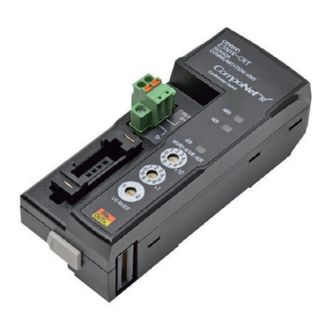
Omron SYSDRIVE MX2 SERIES User manual

Inverter
MX2/RX Series
CompoNet Communications Unit
User’s Manual
I582-E1-04
3G3AX-MX2-CRT-E
3G3AX-RX-CRT-E

OMRON, 2012
All rights reserved. No part of this publication may be reproduced, stored in a retrieval system, or transmitted, in any
form, or by any means, mechanical, electronic, photocopying, recording, or otherwise, without the prior written
permission of OMRON.
No patent liability is assumed with respect to the use of the information contained herein. Moreover, because OMRON
is constantly striving to improve its high-quality products, the information contained in this manual is subject to change
without notice. Every precaution has been taken in the preparation of this manual. Nevertheless, OMRON assumes no
responsibility for errors or omissions. Neither is any liability assumed for damages resulting from the use of the
information contained in this publication.

1
Introduction
CompoNet Communications Unit User’s Manual (I582-E1)
Introduction
Thank you for purchasing a CompoNet Communications Unit (Model: 3G3AX-MX2-CRT-E/
3G3AX-RX-CRT-E). This User's Manual describes the installation and wiring of the
3G3AX-MX2-CRT-E/3G3AX-RX-CRT-E and parameter setting method which is required for the opera-
tion, as well as troubleshooting and inspection methods.
This manual is intended for the following personnel, who must also have knowledge of electrical sys-
tems (an electrical engineer or the equivalent).
• Personnel in charge of introducing the control equipment
• Personnel in charge of designing the control systems
• Personnel in charge of installing and maintaining the control equipment
• Personnel in charge of managing the control systems and facilities
This manual contains information you need to know to correctly use the CompoNet Communications
Unit (Model: 3G3AX-MX2-CRT-E/3G3AX-RX-CRT-E).
Before using the CompoNet Communications Unit, read this manual and gain a full understanding of
the information provided herein.
After you finished reading this manual, keep it in a convenient place so that it can be referenced at any
time.
Make sure this manual is delivered to the end user.
Intended Audience
Notice

Manual Configuration
2CompoNet Communications Unit User’s Manual (I582-E1)
Manual Configuration
This User's Manual is compiled section by section for user's convenience as follows.
Outline
Section 1 Outline This section provides an outline, features, and specifications of the Com-
poNet Communications Unit.
Section 2 CompoNet Communications Unit
Mounting and Wiring
This section provides the part names of the CompoNet Communications
Unit and mounting/wiring methods.
Section 3 Network Startup This section describes inverter parameter settings and CompoNet set-
tings/startup.
Section 4 Remote I/O This section describes the configuration method and function of Remote
I/O (CompoNet assembly I/O).
Section 5 Message Communications This section describes how to read/write inverter parameters by the Mes-
sage communications function (CompoNet Explicit Message).
Section 6 Troubleshooting This section describes the troubleshooting for various problems which
may occur in CompoNet, the inverter, and the CompoNet Communica-
tions Unit.
Appendices This section contains the general object specifications and AC drive
object specifications.

3
Manual Structure
CompoNet Communications Unit User’s Manual (I582-E1)
Manual Structure
The following page structure and symbol icons are used in this manual.
Note The above page is only a sample for illustrative purposes. It is not the actual content of the manual.
Page Structure and Symbol Icons
*1 Node addresses are distributed because the area occupied by a 32-point Output Unit, which occupies more
than one node address, is not overlapping with the area occupied by an 8-point Input Slave.
Allocation to the Special I/O Unit allocation relay area can be performed without CX-Integrator.
Follow the steps below.
1
Power on the inverter(s) first and configure the following settings according to 3-1
Inverter Configuration on page 3-2.
• Set the node address. According to Setting Slave Node Addresses on page 3-15, set the
rotary switches or CompoNet node address (P190).
• Set the type of Remote I/O. Set inverter parameter P046 (Assembly Instance No.) that suits
your application.
Precautions for Correct UsePrecautions for Correct Use
• Be sure to set the type of Remote I/O at this point. No. of occupied words by the CompoNet
Communications Unit varies with the Remote I/O type. Unless the Remote I/O type is set
correctly, automatic network configuration cannot be completed successfully.
• To connect additional CompoNet Slaves, set the node addresses for them simultaneously
at this point.
2
Set the Special I/O Unit number (Machine No.) and communications mode number (MODE)
rotary switches on the Master Unit. Cycle the power supply of the inverter. Then, power on
all network components (Master Unit, other Slaves, communications power supply, etc.).
3
Once the inverter(s) and all network components are powered on, check that the Compo-
Net Communications Unit's LED indicators indicate normal operation.
If everything is correctly configured, both the MS (Module Status) LED and the NS (Network Sta-
tus) LED are lit green.
If the LED indicators indicate a different pattern, please refer to Section 6 Troubleshooting on
page 6-1 to take corrective action.
Allocation
Address
Output Allocation Relay Area Input Allocation Relay Area
Allocation
Relay 15 to 0 Allocation
Relay 15 to 0
00 CIO 2000 32-point Output Unit
[Node Address 0]
CIO 2016 – (Not allocatable)
–7102OIC1002OIC10
(Not allocatable)
8-point Input Unit
*1
[Node Address 1]
02 CIO 2002 This CompoNet Communica-
tions Unit [Node address 2]
Extended Speed I/O setting:
Occupies 2 output words
CIO 2018 This CompoNet Communications
Unit [Node address 2]
Extended Speed I/O setting: Occu-
pies 2 input words
9102OIC3002OIC30
04 CIO 2004 This CompoNet Communica-
tions Unit [Node address 4]
Extended Control I/O setting:
Occupies 4 output words
CIO 2020 This CompoNet Communications
Unit [Node address 4]
Extended Control I/O setting: Occu-
pies 4 input words
1202OIC5002OIC50
2202OIC6002OIC60
3202OIC7002OIC70
08 CIO 2008 –
(Not allocatable)
CIO 2024 32-point Input Unit
[Node Address 8]*1
···············
3-2-3 Allocation to Special I/O Unit Allocation Relay Area
(Communications Mode No. 0 to 3)
3 - 17
CompoNet Communications Unit User’s Manual (I582-E1)
3-2 Network Configuration
3
3-2-4 Allocation Using CX-Integrator (Communication Mode 8)
3 Network Startup
3 Network Startup
3 - 2 CompoNet Communications Unit User’s Manual (I582-E1)
3-1 Inverter Configuration
To use the CompoNet Communications Unit, you need to configure node addresses and the necessary
Remote I/O and other functions.
The configuration of the CompoNet Communications Unit is done through the rotary switches or param-
eters built into the MX2/RX-series Inverter.
This section describes the inverter parameters that must be configured to use the CompoNet Commu-
nications Unit.
Because the settings of the CompoNet Communications Unit vary depending on the type of the
Remote I/O function to be used, information in this section is described for each of the following three
types of Remote I/O.
Precautions for Correct UsePrecautions for Correct Use
• For details about the Remote I/O function, refer to Section 4 Remote I/O on page 4-1.
• Be sure to set the rotary switches and parameters if you install the CompoNet Communica-
tions Unit to an MX2/RX-series Inverter.
Normally, inverter operation can be controlled using the Basic Speed I/O or Extended I/O function
included as standard in CompoNet.
To set the acceleration/deceleration time, however, you need to use OMRON's unique Extended Speed
and Acceleration Control function.
This section explains how to configure these three types of Remote I/O.
Inverter parameters can be configured using the Digital Operator, CX-Drive, or CX-Integrator.
Section Name Applicable Remote I/O Outline
3-1-1 Basic and Extended
Speed I/O Settings
Basic Speed I/O
Extended Speed I/O
Extended Speed and Acceleration Con-
trol
Types of Remote I/O that support
general speed control applica-
tions.
3-1-2 Remote I/O Settings
Using Torque Refer-
ence
Extended Speed and Torque Control
Extended Control I/O
Extended Control I/O and Multi function
I/O Monitor
Types of Remote I/O that include
the Torque Reference and other
interfaces related to torque con-
trol.
These Remote I/O types can be
configured even if the torque ref-
erence is not used.
3-1-3 Special I/O and Flexi-
ble Format Settings
Special I/O
Flexible Format
Types of Remote I/O that utilize
Modbus communication, allow-
ing flexible function selection.
3-1-1 Basic and Extended Speed I/O Settings
Level 2 heading
Level 1 heading
Manual Name
Level 2 heading
Section Number of
Level 1 heading
Level 3 heading
Shows which section the
content of the current
page belongs to.
Shows which sub-section
the content of the current
page belongs to.
Shows which paragraph
the content of the
current page belongs to.
Note,
Supplementary
Information,
Reference Target
A note, supplementary
information, reference
target, etc. are provided
with difference icons.
Operation Steps
Describes the
operation steps.
Level 3 heading

Manual Structure
4CompoNet Communications Unit User’s Manual (I582-E1)
Special information in this manual is classified as follows:
Precautions for Safe Use
Precautions on what to do and what not to do to ensure safe usage of the product.
Precautions for Correct UsePrecautions for Correct Use
Precautions on what to do and what not to do to ensure proper operation and performance.
Additional Information
Additional information to read as required.
This information is provided to increase understanding or make operation easier.
Special Information

5
Sections in this Manual
CompoNet Communications Unit User’s Manual (I582-E1)
1
2
3
4
5
6
A
I
1
2
3
4
5
6
A
I
Outline
CompoNet Communications Unit
Mounting and Wiring
Network Startup
Remote I/O
Message Communications
Troubleshooting
Appendices
Index
Sections in this Manual

6CompoNet Communications Unit User’s Manual (I582-E1)
CONTENTS
CONTENTS
Introduction ..............................................................................................................1
Manual Configuration ..............................................................................................2
Manual Structure ......................................................................................................3
Sections in this Manual ...........................................................................................5
CONTENTS ................................................................................................................6
Read and Understand this Manual .........................................................................9
Safety Precautions .................................................................................................12
Precautions for Safe Use.......................................................................................15
Precautions for Correct Use..................................................................................17
Regulations and Standards...................................................................................19
Trademarks .............................................................................................................20
Items to Check After Unpacking ...........................................................................21
Related Manuals .....................................................................................................23
Revision History .....................................................................................................24
Section 1 Outline
1-1 Outline of CompoNet Communications Unit ...................................................................... 1-2
1-2 Overview of CompoNet Communications........................................................................... 1-5
1-2-1 Functions..................................................................................................................................... 1-5
1-2-2 Features...................................................................................................................................... 1-5
1-2-3 Configuration............................................................................................................................... 1-9
1-2-4 Maximum Number of Inverter Connections............................................................................... 1-10
1-3 Specifications ...................................................................................................................... 1-11
1-4 Restrictions on Use............................................................................................................. 1-15
1-4-1 Supported Inverters................................................................................................................... 1-15
1-4-2 Inverter Safety (ISO13849-1) .................................................................................................... 1-15
1-4-3 Restrictions ............................................................................................................................... 1-16
Section 2 CompoNet Communications Unit Mounting and Wiring
2-1 Name and Setting of Each CompoNet Communications Unit Component ...................... 2-2
2-1-1 Name and Setting of Each Component....................................................................................... 2-2
2-1-2 LED Indicators............................................................................................................................. 2-4
2-1-3 Rotary Switches .......................................................................................................................... 2-5
2-2 Installation.............................................................................................................................. 2-6
2-2-1 Mounting Procedure of CompoNet Communications Unit on MX2-series Inverter ..................... 2-7
2-2-2 Mounting Procedure of CompeNet Communications Unit on RX-series Inverter ..................... 2-10
2-2-3 Operating Environment ............................................................................................................. 2-15

7
CompoNet Communications Unit User’s Manual (I582-E1)
CONTENTS
2-2-4 Connector Wiring...................................................................................................................... 2-15
Section 3 Network Startup
3-1 Inverter Configuration........................................................................................................... 3-2
3-1-1 Basic and Extended Speed I/O Settings..................................................................................... 3-2
3-1-2 Remote I/O Settings Using Torque Reference............................................................................ 3-6
3-1-3 Special I/O and Flexible Format Settings ...................................................................................3-9
3-1-4 Utilizing Multi-function Inputs/Outputs for Host......................................................................... 3-12
3-2 Network Configuration........................................................................................................3-14
3-2-1 EDS File Installation ................................................................................................................. 3-14
3-2-2 CompoNet Communications Network Configuration ................................................................ 3-14
3-2-3 Allocation to Special I/O Unit Allocation Relay Area (Communications Mode No. 0 to 3) ........ 3-16
3-2-4 Allocation Using CX-Integrator (Communication Mode 8) ........................................................ 3-17
3-2-5 Registration Table Configuration............................................................................................... 3-20
3-3 Editing Parameters in Parameter Dialog with EDS File ................................................... 3-24
3-3-1 How to Edit Parameters in Parameter Dialog with EDS File .................................................... 3-24
3-3-2 Restrictions of Edit Device Parameters Function with EDS File............................................... 3-25
3-4 Editing Parameters with CX-Drive ..................................................................................... 3-28
3-4-1 Connecting CX-Drive (via CompoNet)...................................................................................... 3-28
3-4-2 Outline of CX-Drive................................................................................................................... 3-33
Section 4 Remote I/O
4-1 Remote I/O Configuration .....................................................................................................4-2
4-1-1 Remote I/O Types....................................................................................................................... 4-2
4-1-2 Remote I/O Selection................................................................................................................. 4-3
4-2 Basic and Extended Speed I/O............................................................................................. 4-4
4-2-1 Basic Speed I/O (20/70) ............................................................................................................. 4-4
4-2-2 Extended Speed I/O (21/71) ....................................................................................................... 4-5
4-2-3 Extended Speed and Acceleration Control (110/111) ................................................................. 4-7
4-3 Remote I/O with Torque Reference Support ..................................................................... 4-10
4-3-1 Torque Control Configuration.................................................................................................... 4-10
4-3-2 Extended Speed and Torque Control (123/173) ........................................................................4-11
4-3-3 Extended Control I/O (101/151/153).........................................................................................4-13
4-3-4 Extended Control I/O and Multi function I/O Monitor (101/153)................................................ 4-15
4-4 Special I/O and Flexible Format ......................................................................................... 4-17
4-4-1 Frequency Reference/RUN Command Selection ..................................................................... 4-17
4-4-2 Special I/O (100/150)................................................................................................................ 4-17
4-4-3 Flexible Format (139/159)......................................................................................................... 4-20
4-5 When to Input the RUN Command after Establishment of Communications................ 4-22
Section 5 Message Communications
5-1 Outline of Explicit Message..................................................................................................5-2
5-2 Sending Messages from CS/CJ-series ................................................................................ 5-3
5-2-1 How to Issue Explicit Messages by CMND Instruction ............................................................... 5-3
5-2-2 When to Issue/Read an Explicit Message .................................................................................. 5-5
5-3 Outline of Message Function and Response...................................................................... 5-7
5-4 Parameter Read/Write (Class 64 hex) ................................................................................ 5-10
5-4-1 Supported Service Codes......................................................................................................... 5-10
5-4-2 Parameter Data Size ................................................................................................................ 5-10
5-4-3 Parameter Read/Write Data ......................................................................................................5-11
5-4-4 Saving Changes to Holding Registers (ENTER Command)..................................................... 5-12

8CompoNet Communications Unit User’s Manual (I582-E1)
CONTENTS
5-4-5 Parameter Class/Instance/Attribute .......................................................................................... 5-12
5-4-6 Ladder Programming Example .................................................................................................5-13
5-5 Parameter Read/Write (Class 65 hex) ................................................................................ 5-14
5-5-1 Supported Service Codes ......................................................................................................... 5-14
5-5-2 Supported Instance and Attribute Codes ..................................................................................5-14
Section 6 Troubleshooting
6-1 Outline of Error Indication .................................................................................................... 6-2
6-2 Errors on a Communications Line ....................................................................................... 6-3
6-3 Errors on Inverter or CompoNet Communications Unit .................................................... 6-5
6-3-1 Error Codes Related to CompoNet Communications Error ........................................................ 6-5
6-3-2 Error Codes Related to CompoNet Communications Unit .......................................................... 6-7
6-3-3 Parameter Setting Error in CompoNet Communications Unit ..................................................... 6-8
6-4 Errors Related to Message Communications ................................................................... 6-10
6-4-1 FINS Message Errors (CS/CJ-series) ....................................................................................... 6-10
6-4-2 Explicit Message Errors ............................................................................................................ 6-11
6-5 Special I/O Errors ................................................................................................................ 6-12
6-6 Removing CompoNet Communications Unit .................................................................... 6-13
6-6-1 How to Remove CompoNet Communications Unit - MX2-series.............................................. 6-14
6-6-2 How to Remove CompoNet Communications Unit - RX-series ................................................ 6-15
Appendices
A-1 General Object Specifications..............................................................................................A-2
A-1-1 Identity Object (Class 01 hex).....................................................................................................A-2
A-1-2 Message Router Object (Class 02 hex) ......................................................................................A-4
A-1-3 Assembly Object (Class 04 hex) .................................................................................................A-5
A-1-4 Connection Object (Class 05 hex) ..............................................................................................A-6
A-1-5 Discrete Input Point Object (Class 08 hex) .................................................................................A-7
A-1-6 Discrete Output Point Object (Class 09 hex) ..............................................................................A-8
A-1-7 Unit Parameter Object (Class 94 hex) ........................................................................................A-9
A-1-8 CompoNet Link Object (Class F7 hex)......................................................................................A-10
A-2 AC Drive Object Specifications..........................................................................................A-11
A-2-1 Motor Data Object (Class 28 hex).............................................................................................A-11
A-2-2 Control Supervisor Object (Class 29 hex).................................................................................A-12
A-2-3 AC/DC Drive Object (Class 2A hex)..........................................................................................A-15
Index

9
Read and Understand this Manual
CompoNet Communications Unit User’s Manual (I582-E1)
Read and Understand this Manual
Warranty and Limitations of Liability
WARRANTY
OMRON's exclusive warranty is that the products are free from defects in materials and workmanship for a period of
one year (or other period if specified) from date of sale by OMRON.
OMRON MAKES NO WARRANTY OR REPRESENTATION, EXPRESS OR IMPLIED, REGARDING NONIN-
FRINGEMENT, MERCHANTABILITY, OR FITNESS FOR PARTICULAR PURPOSE OF THE PRODUCTS. ANY
BUYER OR USER ACKNOWLEDGES THAT THE BUYER OR USER ALONE HAS DETERMINED THAT THE
PRODUCTS WILL SUITABLY MEET THE REQUIREMENTS OF THEIR INTENDED USE. OMRON DISCLAIMS ALL
OTHER WARRANTIES, EXPRESS OR IMPLIED.
LIMITATIONS OF LIABILITY
OMRON SHALL NOT BE RESPONSIBLE FOR SPECIAL, INDIRECT, OR CONSEQUENTIAL DAMAGES, LOSS
OF PROFITS OR COMMERCIAL LOSS IN ANY WAY CONNECTED WITH THE PRODUCTS, WHETHER SUCH
CLAIM IS BASED ON CONTRACT, WARRANTY, NEGLIGENCE, OR STRICT LIABILITY.
In no event shall the responsibility of OMRON for any act exceed the individual price of the product on which liability
is asserted.
IN NO EVENT SHALL OMRON BE RESPONSIBLE FOR WARRANTY, REPAIR, OR OTHER CLAIMS REGARDING
THE PRODUCTS UNLESS OMRON'S ANALYSIS CONFIRMS THAT THE PRODUCTS WERE PROPERLY HAN-
DLED, STORED, INSTALLED, AND MAINTAINED AND NOT SUBJECT TO CONTAMINATION, ABUSE, MISUSE,
OR INAPPROPRIATE MODIFICATION OR REPAIR.

Read and Understand this Manual
10 CompoNet Communications Unit User’s Manual (I582-E1)
Application Considerations
SUITABILITY FOR USE
OMRON shall not be responsible for conformity with any standards, codes, or regulations that apply to the combina-
tion of products in the customer's application or use of the products.
At the customer's request, OMRON will provide applicable third party certification documents identifying ratings and
limitations of use that apply to the products. This information by itself is not sufficient for a complete determination of
the suitability of the products in combination with the end product, machine, system, or other application or use.
The following are some examples of applications for which particular attention must be given. This is not intended to
be an exhaustive list of all possible uses of the products, nor is it intended to imply that the uses listed may be suit-
able for the products:
• Outdoor use, uses involving potential chemical contamination or electrical interference, or conditions or uses not
described in this manual.
• Nuclear energy control systems, combustion systems, railroad systems, aviation systems, medical equipment,
amusement machines, vehicles, safety equipment, and installations subject to separate industry or government
regulations.
• Systems, machines, and equipment that could present a risk to life or property. Please know and observe all prohi-
bitions of use applicable to the products.
NEVER USE THE PRODUCTS FOR AN APPLICATION INVOLVING SERIOUS RISK TO LIFE OR PROPERTY
WITHOUT ENSURING THAT THE SYSTEM AS A WHOLE HAS BEEN DESIGNED TO ADDRESS THE RISKS,
AND THAT THE OMRON PRODUCTS ARE PROPERLY RATED AND INSTALLED FOR THE INTENDED USE
WITHIN THE OVERALL EQUIPMENT OR SYSTEM.
PROGRAMMABLE PRODUCTS
OMRON shall not be responsible for the user's programming of a programmable product, or any consequence
thereof.

11
Read and Understand this Manual
CompoNet Communications Unit User’s Manual (I582-E1)
Disclaimers
CHANGE IN SPECIFICATIONS
Product specifications and accessories may be changed at any time based on improvements and other reasons. It is
our practice to change model numbers when published ratings or features are changed, or when significant construc-
tion changes are made. However, some specifications of the products may be changed without any notice. When in
doubt, special model numbers may be assigned to fix or establish key specifications for your application on your
request. Please consult with your OMRON representative at any time to confirm actual specifications of purchased
products.
DIMENSIONS AND WEIGHTS
Dimensions and weights are nominal and are not to be used for manufacturing purposes, even when tolerances are
shown.
PERFORMANCE DATA
Performance data given in this manual is provided as a guide for the user in determining suitability and does not con-
stitute a warranty. It may represent the result of OMRON's test conditions, and the users must correlate it to actual
application requirements. Actual performance is subject to the OMRON Warranty and Limitations of Liability.
ERRORS AND OMISSIONS
The information in this manual has been carefully checked and is believed to be accurate; however, no responsibility
is assumed for clerical, typographical, or proofreading errors, or omissions.

Safety Precautions
12 CompoNet Communications Unit User’s Manual (I582-E1)
Safety Precautions
To ensure that the CompoNet Communications Unit (Model: 3G3AX-MX2-CRT-E/3G3AX-RX-CRT-E) is
used safely and correctly, be sure to read this Safety Precautions section and the main text before
using the product.
Learn all items you should know before use, regarding the equipment as well as required safety infor-
mation and precautions.
Make an arrangement so that this manual also gets to the end user of this product.
After reading this manual, keep it in a convenient place so that it can be referenced at any time.
The following notation is used in this manual to provide precautions required to ensure safe usage of a
CompoNet Communications Unit (Model: 3G3AX-MX2-CRT-E/3G3AX-RX-CRT-E). The safety precau-
tions that are provided are extremely important to safety. Always read and heed the information pro-
vided in all safety precautions.
The following notation is used.
Definition of Precautionary Information
Meaning of Warning Indication
Indicates an imminently hazardous situation which, if not avoided, is likely
to result in serious injury or may result in death. Additionally there may be
severe property damage.
Indicates a potentially hazardous situation which, if not avoided, will result
in minor or moderate injury, or may result in serious injury or death.
Additionally there may be significant property damage.
Indicates a potentially hazardous situation which, if not avoided, may
result in minor or moderate injury or in property damage.
Explanation of Symbols
This symbol indicates a prohibited item (an item you must not do).
The specific instruction is indicated using an illustration or text inside or near .
The symbol shown to the left indicates "disassembly prohibited."
This symbol indicates danger and caution.
The specific instruction is indicated using an illustration or text inside or near .
The symbol shown to the left indicates "beware of electric shock."
The filled circle symbol indicates operations that you must do.
The specific operation is shown in the circle and explained in text.
This example shows a general precaution for something that you must do.
DANGER
WARNING
Caution

13
Safety Precautions
CompoNet Communications Unit User’s Manual (I582-E1)
Do not attempt to remove the terminal block cover or disconnect and reconnect the CompoNet Communications
Unit during power on or within 10 minutes after power off.
Doing so may result in severe injury due to electric shock.
Security Measures
Anti-virus protection
Install the latest commercial-quality antivirus software on the computer connected to the control system
and maintain to keep the software up-to-date.
Security measures to prevent unauthorized access
Take the following measures to prevent unauthorized access to our products.
• Install physical controls so that only authorized personnel can access control systems and equipment.
• Reduce connections to control systems and equipment via networks to prevent access from untrusted
devices.
• Install firewalls to shut down unused communications ports and limit communications hosts and isolate
control systems and equipment from the IT network.
• Use a virtual private network (VPN) for remote access to control systems and equipment.
• Adopt multifactor authentication to devices with remote access to control systems and equipment.
• Set strong passwords and change them frequently.
• Scan virus to ensure safety of USB drives or other external storages before connecting them to control
systems and equipment.
Data input and output protection
Validate backups and ranges to cope with unintentional modification of input/output data to control systems
and equipment.
• Checking the scope of data
• Checking validity of backups and preparing data for restore in case of falsification and abnormalities
• Safety design, such as emergency shutdown and fail-soft operation in case of data tampering and
abnormalities
Data recovery
Backup data and keep the data up-to-date periodically to prepare for data loss.
When using an intranet environment through a global address, connecting to an unauthorized terminal
such as a SCADA, HMI or to an unauthorized server may result in network security issues such as spoof-
ing and tampering. You must take sufficient measures such as restricting access to the terminal, using a
terminal equipped with a secure function, and locking the installation area by yourself.
When constructing an intranet, communication failure may occur due to cable disconnection or the influ-
ence of unauthorized network equipment. Take adequate measures, such as restricting physical access to
network devices, by means such as locking the installation area.
When using a device equipped with the SD Memory Card function, there is a security risk that a third party
may acquire, alter, or replace the files and data in the removable media by removing the removable media
or unmounting the removable media.
Please take sufficient measures, such as restricting physical access to the Controller or taking appropriate
management measures for removable media, by means of locking the installation area, entrance manage-
ment, etc., by yourself.
DANGER
WARNING

Safety Precautions
14 CompoNet Communications Unit User’s Manual (I582-E1)
Inverters contain high voltage parts and short-circuits may sometimes cause product damage or property
damage. Measures must be taken to prevent chips, lead-wire pieces, or other metal waste from entering
the product, for example, by installing a cover.
Do not attempt to disassemble, repair, or modify the CompoNet Communications Unit.
Doing so may result in injury.
Caution

15
Precautions for Safe Use
CompoNet Communications Unit User’s Manual (I582-E1)
Precautions for Safe Use
Do not store or use the CompoNet Communications Unit in the following environment:
• Locations subject to direct sunlight
• Locations subject to ambient temperatures outside the range specified in the specifications
• Locations subject to relative humidity outside the range specified in the specifications
• Locations subject to condensation as the result of severe temperature fluctuations
• Locations subject to corrosive or flammable gases
• Locations near flammable materials
• Locations subject to dust, salt spray, or iron powder
• Locations subject to water, oil, or chemical splashes
• Locations subject to direct shock or vibration
• Do not drop or apply strong impact on the product. Doing so may result in damaged parts or malfunc-
tion.
• When transporting the inverter with a mounted CompoNet Communications Unit, do not hold the
CompoNet Communications Unit.
• Do not remove the cover of the CompoNet Communications Unit. Tighten an Unit fixation screw to
the specified torque.
• Install an appropriate stopping device to ensure safety. In particular, if configured to operate continu-
ously even in the event of a communications error, the inverter may not stop, resulting in equipment
damage.
• If the CompoNet Communications Unit is used in the following locations, provide sufficient shielding
measures. Using the CompoNet Communications Unit in any of these locations may result in equip-
ment damage.
Locations subject to static electricity or other forms of noise
Locations subject to strong electromagnetic fields
Locations close to power lines
• During installation, wiring, and network setting on the CompoNet Communications Unit, please refer
to applicable sections of this manual to ensure the correct connection and configuration procedures.
• When removing the CompoNet Communications Unit, do not pull the flat cable.
• When mounting the CompoNet Communications Unit, be sure that the flat cable is not pinched.
• When mounting the CompoNet Communications Unit, be careful about burrs of the break-outs on
the inverter.
• Be sure to confirm the permissible range of motors and machines before operation because the
speed can be set from low to high.
• Before starting the CPU Unit and inverter programs, check the program contents as well as the inter-
actions between these programs.
Installation and Storage
Transportation, Installation, and Wiring
Operation and Adjustment

Precautions for Safe Use
16 CompoNet Communications Unit User’s Manual (I582-E1)
• Be sure to confirm safety before conducting maintenance, inspection or parts replacement.
• Invalid parameter configuration may result in a communications error, interrupting the communica-
tions function of other units. Before participating in the network, make sure that the communications
configuration parameters are set properly.
• Using a support tool to write all inverter parameters causes the CompoNet configuration parameters
to be overwritten. Before reconnecting to CompoNet, make sure that the address and I/O allocations
are correct.
Maintenance and Inspection

17
Precautions for Correct Use
CompoNet Communications Unit User’s Manual (I582-E1)
Precautions for Correct Use
Be sure to meet the constraints on the mounting direction of the inverter.
Mounting the CompoNet Communications Unit disables the Inverter's Modbus-RTU communication
capability.
Comply with the local ordinance and regulations when disposing of the product.
• The product's warning label is located in the following position when the CompoNet Communications
Unit is mounted on the inverter.
• For the model 3G3AX-RX-CRT-E, the warning label is attached to the inverter.
• Be sure to follow the instructions.
Note The appearance differs depending on the capacity of the inverter.
The model 3G3AX-MX2-CRT-E (for the MX2-series) has an English warning label attached when
shipped from the factory.
Affix an appropriate language label included with the product on it if necessary.
Installation
Modbus-RTU Communication
Product Disposal
Warning Labels
Warning Description
STOP
RESET
RUN
Hz
A
ALM
PRG
3G3MX2
INVERTER
RUN
PWR
SYSDRIVE
200V
3PHASE
1
2
3
4
5
6
7
8
9
0
1
2
3
4
5
6
7
8
9
0
1
2
3
4
5
6
7
8
9
0
1
2
3
4
5
6
7
8
9
0

Precautions for Correct Use
18 CompoNet Communications Unit User’s Manual (I582-E1)
There is a restriction on the unit version of the inverter that can be used with the CompoNet Communi-
cations Unit.
Make sure that your inverter's unit version is 1.1 or later.
Make sure that your inverter is 3G3RX-V1 series (unit version 2.0 or later).
Note The inverter unit version is indicated on the nameplate attached to the inverter.
Supported Inverter Versions
Other manuals for SYSDRIVE MX2 SERIES
9
This manual suits for next models
3
Table of contents
Other Omron Conference System manuals

Omron
Omron V680 - 2 User manual

Omron
Omron V670 Series User manual

Omron
Omron ZS-CRT User manual

Omron
Omron V640 User manual

Omron
Omron C200HW-CORT21-V1 User manual

Omron
Omron Sysmac E3X-ECT User manual

Omron
Omron E3NW-CCL User manual

Omron
Omron SMARTSLICE - 04-2008 User manual

Omron
Omron DRT1-COM User manual

Omron
Omron C200HW-COM01 User manual