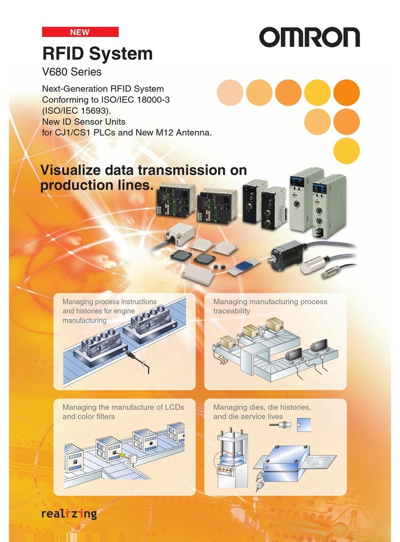
Omron V670 Series User manual

V670 Series
Electromagnetic Inductive RFID System
V670-H11/H51/H51Q (Compact Antenna)
V670-D13F01/D13F01H/D13F03 (Compact Tag)
V670-CD1D-V1 (Controller)
Ideal for miniature electronic devices, the manufacture
and assembly of components for compact cars,
and management of components
for mounting equipment.
Ideal for miniature electronic devices, the manufacture
and assembly of components for compact cars,
and management of components
for mounting equipment.
A Compact Antenna and Compact Tag join the high-speed,
long-life V670-series lineup to provide powerful support for
improving productivity and traceability.
A Compact Antenna and Compact Tag join the high-speed,
long-life V670-series lineup to provide powerful support for
improving productivity and traceability.

Line Processing Instructions
and Quality History Management
●
Processes where processing is performed without stopping
● Production lines with a short tact time
●
Lines performing high-mix, high-volume production
Line Processing Instructions
and Quality History Management
●
Processes where processing is performed without stopping
● Production lines with a short tact time
●
Lines performing high-mix, high-volume production
Machine Control
●
Control of installations performing high-speed processing
● Control of conveyance installations
Machine Control
●
Control of installations performing high-speed processing
● Control of conveyance installations
Applications
and narrow-pitch mounting. Greater flexibility with mounting location and operating conditions allows use in a much wider range of applications.
High-speed Processing Comparable to ON/OFF-sensor Operation
●Auto Repeat Function
Communications are performed whenever a Tag
enters the communications range. Communications
are performed only once with the same Tag.
Antenna
Tag
●Tag Specification
The V670 communicates only with the Tags that
it communicated with previously or with the other
Tags, depending on the specification.
Antenna
If the Tag specification is for different Tags, the system will wait for
the Tag not yet communicated with before performing communications.
Tag previously
communicated with
Tag not yet
communicated with
●Repeat Input Trigger
Each time the rising edge of the input signal is detected, the
existence of a Tag is confirmed and communications are per-
formed. If there is no Tag, an error is generated.
Antenna
Tag
Photoelectric sensor, etc.
Controller's trigger input signal
High-speed movement
Tag
Antenna
Controller
(Synchronous sensor)
Trigger input
Coincidence output
Error output
Self-execution System
Previous System
Total processing time
Host communications
(command)
Tag
communications
Host communications
(response)
Discrimination
and instructions
Tag
communications
Discrimination
and instructions
Flow Control of Moving Objects
¥ RGV
¥ OHT
¥ Carts
¥ Sorters
*FeRAM: Ferroelectric RAM
The V670 Series performs high-speed data
communications with battery-free Tags. Reading
and writing of Tag data can be performed at speeds
allowing operation that seems like ON/OFF-sensor
operation. Even in production lines for small items
with short processing times for each process, the
communications time does not affect the tact time. It
is also now possible to handle more data in
processes where, until now, the amount of data has
been limited to reduce processing time.
Reliable Reading and Writing during Operation
A short communications processing time means that
data is read and written reliably without stopping the
Tags. This means that
reading and writing can be
performed while Tags and
Antennas are moving.
Even in cases where Tags
are mounted to moving
pallets, changes to con-
veyance control to allow
access are unnecessary.
Simplified conveyance
control contributes to cost
reductions in installations.
Communications Control with a Broad Range of Functions
V670-series products are equipped with a wide variety of communica-
tions functions that allow host devices to easily perform communica-
tions control for the Tags. Using the auto repeat and repeat input trig-
ger functions, repeated communications with several Tags can be per-
formed automatically with a single command. Using the tag specifica-
tion function, in cases where data
is written to individual Tags or
where more complex commands
are used, such as applications
where writing is performed after
reading, consideration of the tim-
ing with which Tags enter the
communications range is not re-
quired.
Simple Control and High-speed Response
Achieved with Self-execution Mode
In self-execution mode, the V670 repeats communications according
to previously set conditions, discriminates data, and turns ON output
accordingly. Control for simple sorting
can be performed just using the Control-
ler, without connecting a host device. The
time required for exchanging commands
and responses is eliminated, enabling the
time from communications to result out-
put to be significantly reduced. This
makes it possible to perform control for
lines and installations requiring high-
speed responsiveness.
Compact and Slim
The Compact Tags boast stream-
lined dimensions of 8 x 16 x t3.5 mm
(V670-D13F01). Tags both with and
without mounting holes are available
to suit the application. Also, the
mounting direction of the Tags can
be changed to allow, for example,
mounting on the top of narrow pallets
or on the side of slim pallets. Using
the V670-A81 Attachment makes it possible to mount Tags on
metal surfaces. The Compact Antenna boasts dimensions of M18
x 43 mm (V670-H51). The Antenna is mounted with the screws of
the Controller and so fine adjustment of the communications dis-
tance can be performed with ease.
Narrow-pitch Mounting
High Resistance to the Environment
The Tags and Antennas all conform to the IP67 (IEC) degree of
protection. In particular, the Compact Antenna (V670-H51Q)
uses a fluororesin case, and also conforms to IP67g (JEM; water
resistance and oil resistance). PPS resin, which is high in chemi-
cal resistance, is used in the case material for the Compact Tag
(V670-D13F01/D13F01H) enabling use in harsh environments
subject to chemicals, oils, and coolants.
Reduced Maintenance with No Battery or Tag Replacement
The V670 Series uses a FeRAM (ferroelectric RAM) with a serv-
ice life of 1,000 million times and so there is essentially no re-
striction on the memory service life. Even if the memory were ac-
cessed once a second, 24 hours a day, 365 days a year, it would
still last more than 10 years. In production lines for miniature de-
vices where pallets are reused with a high frequency, or in appli-
cations where data is frequently rewritten, maintenance such as
battery replacement or Tag replacement is unnecessary.
Tag V670-D13F03
Controller
V670-CD1D-V1
Antenna
V670-H11
OK
NG
Inspection, Selection, and Classification
of Food Products
Assembly Management for Miniature
Electronic Devices
Manufacture and Inspection of Electronic Components
and Secondary Batteries
Management of Components for Mounting Equipment
Applications
Communications Time
Approx. 5 ms (reading/writing 12 bytes)
Approx. 14 ms (reading/writing 128 bytes)
Combination of V670-H51 and V670-D13F01 (Perpendicular Mounting)
Maximum speed: 100 m/min (12 bytes)
Maximum speed: 36 m/min (128 bytes)
Combination of V670-H11 and V670-D13F03
Maximum speed: 360 m/min (12 bytes)
Maximum speed: 150 m/min (128 bytes)
16 mm
30 mm
Tag
Antenna
Water!
V670-D13F01
V670-D13F01
Ta g
Tag
V670-H51
V670-H51
Antenna51
Antenna51
V670-D13F01
Ta g
V670-H51
Antenna
V670-H51
V670-H51
Antenna
Antenna
V670-D13F01 Tag
V670-D13F01 Tag
V670-H51
Antenna
V670-D13F01 Tag
5mm*
Oil!
Chemicals!
V670-D13F01(H)
V670-H51(Q)
Ta g
V670-D13F03
Antenna
V670-H11
Ta g
V670-D13F01H
Antenna
V670-H51
Attachment
V670-A81
Fast
FastFast
Tough
ToughTough
Versatile
VersatileVersatile
Efficient
Efficient
Efficient
Easy
EasyEasy
100 mm
V670-H11
70 mm
V670-D13F03
V670-D13F01
Ta g
V670-H51Q
Antenna
The speeds given above are the maximum movement speeds in good condi-
tions. When designing the system, give consideration to the actual installa-
tion conditions. Also, be sure to thoroughly evaluate the operating environ-
ment before use.
*
Without using the Extension Cable for the V670-H51 Antenna.*
The V670 Series uses a communications
method with minimal mutual interference
and so operation is possible with Tags
and Antennas separated only by small
gaps; miniature pallets carrying Tags, for
example, can be used back-to-back. In
assembly lines for miniature devices with
small gaps between processes, the sys-
tem can be installed without worrying
about mutual interference between
Antennas for neighboring
processes.
1,000million times min.
In addition to high-speed processing and long-life memory, the V670 Series now offers space savings, high resistance to the environment,

4Electromagnetic Inductive RFID System V670
Electromagnetic Inductive RFID System
V670
High-speed, Long-life, Battery-less RFID
System
• High-speed communications requiring only 14 ms to read or
write 128 bytes of data.
• Long-life battery-free tags to read and write data 1,000 million
times.
• Versatile functions, such as auto repeat, repeat input trigger,
and tag specification.
• Self-execution mode for data processing with no host controller
intervention.
• CE marking/FCC approvals.
Ordering Information
■List of Models
Product Model Shape/Specification
ID Tag V670-D13F03 40 ×40 ×4.5 mm 128 bytes
V670-D13F01 8 ×16 ×3.5 mm
V670-D13F01H 8 ×28 ×3.5 mm
3.2 dia. mounting
holes
Antenna V670-H11 40 ×53 ×23 mm 2-m cable
Length can be extended with a special Antenna Ex-
tension Cable.
V670-H51
(See note.)
M18 ×43 mm
V670-H51Q
(See note.)
M18 ×47 mm
Chemical-resistant
Controller V670-CD1D-V1 90 ×66 ×75 mm RS-232C interface operating at 24 VDC with a single
antenna connector
Supports the V670-H51/H51Q
Antenna Extension
Cables
V670-A40 3 m Material: Polyvinyl chloride
Connectors are not watertight.
V670-A41 10 m
V670-A42 18 m
V670-A43 28 m
Attachment V670-A81 8 ×28 ×6 mm
3.2 dia. mounting
holes
To mount the V670-D13F01H to metal surfaces

Electromagnetic Inductive RFID System V670 5
Note: The V670-CD1D cannot be used. Be sure to use the V670-CD1D-V1.
Specifications
■ID Tags
Note: The number of accesses is the total number of read or write communications.
■Antenna
Note: 1. The connector is not watertight.
2. The communications distance will be reduced if the cable is extended. The communications distance also depends on the type of exten-
sion cable used. Refer to Transmission Distance Specifications for details.
Programming
Console
C200H-PRO27-E Operation monitor, set value display, communica-
tions, test communications, and error log functions.
Programming
Console
Conversion Cable
V700-P10 2 m Connects the V670-CD1D and C200H-PRO27-E.
Product Model Shape/Specification
Item V670-D13F01 V670-D13F01H V670-D13F03
Memory capacity 128 bytes
Memory type FeRAM
Memory life Number of accesses: 1,000 million times (See note.)
Data storage time 10 years (after the data is written or read)
Ambient temperature Operating: −10 to 70°C
Ambient temperature Storage: −10 to 70°C
Ambient humidity Operating: 35% to 95% Operating: 35% to 85%
Degree of protection IEC 60529 IP67
Vibration resistance 10 to 2,000 Hz, 1.5-mm double amplitude at 150 m/s2acceleration with 10 sweeps in X, Y, and Z directions for 15 minutes
each
Shock resistance 500 m/s2in X, Y, and Z directions 3 times each (18 times in total)
Material PPS, filled with Epoxy resin ABS, filled with epoxy resin
Weight Approx. 1 g Approx. 1 g Approx. 6 g
Item V670-H51 V670-H51Q V670-H11
Oscillation frequency 13.56 MHz
Ambient temperature Operating: −10 to 70°C
Ambient temperature Storage: −25 to 75°C Storage: −25 to 85°C
Ambient humidity Storage: 35% to 95% Storage: 35% to 85%
Insulation resistance 20 MΩmin.
Dielectric strength 1,000 VAC for 1 minute between the terminals and case with a current leakage of 5 mA
Degree of protection IEC 60529 IP67 (See note 1.) IEC 60529 IP67
IP67g (transmission surface only, JEM
standard) (See note 1.)
IEC 60529 IP67 (See note 1.)
Vibration resistance 10 to 500 Hz, 1.5-mm double amplitude at 100 m/s2acceleration with 10 sweeps
in X, Y, and Z directions for 11 minutes each
10 to 150 Hz, 0.7-mm double amplitude
at 50 m/s2acceleration with 10 sweeps
in X, Y, and Z directions for 8 minutes
each
Shock resistance 300 m/s2in X, Y, and Z directions 3 times each (18 times in total)
Material PBT/brass, filled with epoxy resin Fluororesin, filled with epoxy resin ABS, filled with epoxy resin
Cable length 2 m (total length: 30 m (See note 2.))
Tightening torque 70 N·m 2 N·m ---
Approved standards FCC/R&TTE (CE)
Weight 140 g 130 g Approx. 160 g

6Electromagnetic Inductive RFID System V670
■Controller
Note: The V670-CD1D-V1 must be used when using the V670-H51/H51Q. The V670-CD1D cannot be used.
System Configuration
Note: 1. The V670-CD1D-V1 must be used when using the V670-H51/H51Q. The V670-CD1D cannot be used.
2. When extending the antenna cable, do not use any cable other than the Antenna Extension Cables from OMRON.
Item V670-CD1D-V1 (See note.)
Host interface
specifications
RS-232C
Number of
connectable
antennas
1
Power supply
voltage
24 VDC ±10%
Power consumption 7 W max.
Ambient temperature Operating: 0 to 55°C (with no icing)
Ambient humidity Operating: 35% to 85% (with no condensation)
Ambient temperature Storage: −20 to 75°C (with no icing)
Insulation resistance 20 MΩmin.
Dielectric strength 1,000 VAC for 1 minute in all the above combinations with a maximum leakage current of 20 mA
Degree of protection Panel mounted
Vibration resistance 10 to 150 Hz, 0.2-mm double amplitude at 15 m/s2acceleration with 10 sweeps in X, Y, and Z directions for 8 minutes
each.
Shock resistance 15 m/s2in X, Y, and Z directions 3 times each (18 times in total)
Ground Ground at a resistance of less than 100 Ω
Materials PC/ASA resin
Approved standards FCC/R&TTE (CE)
Weight Approx. 270 g
V670-A40
V670-A41
V670-A42
V670-A43
V700-P10 C200H-PRO27
V670-H11
V670-H51
V670-H51Q
V670-D13F03
V670-D13F01
V670-D13F01H
V670-CD1D-V1
ID Tag Antenna Antenna Extension
Cable (See note 2.)
Programming
Console Conversion
Cable
Programming
Console
Host with
RS-232C interface
Controller
(See note 1.)
(See note 1.)

Electromagnetic Inductive RFID System V670 7
■Transmission Distance Specifications
Note: 1. The transmission distance is reduced if an Extension Cable is used. Also, the transmission distance varies with the type of Extension
Cable.
2. When the background object of the antenna is metal, the communications area is almost the same. If the tag is attached on metal without
a gap, no communications will be possible. For details, refer to the V670 User's Manual (Z148-E1).
Antenna/Controller ID Tag Transmission distance Measurement conditions
Without
Extension
Cable
With Extension Cable
5.0 to 23.0
(axial offset:
±1)
A40 (3 m) 5.0 to 21.5
A41 (10 m) 5.0 to 21.0
A42 (18 m) 5.0 to 20.5
A43 (28 m) 5.0 to 20.0
0.5 to 5.0
(axial offset:
±1)
A40 (3 m) 0.5 to 5.0
A41 (10 m)
A42 (18 m) 0.5 to 4.0
A43 (28 m)
0.5 to 4.5
(axial offset:
±1)
A40 (3 m) 0.5 to 4.5
A41 (10 m)
A42 (18 m) 0.5 to 3.5
A43 (28 m)
V670-H11 + V670-CD1D-V1
V670-D13F03
Antenna ID Tag
Non-metallic Non-metallic
(See note 2.)
Transmission distance
V670-H51 + V670-CD1D-V1
V670-D13F01
Antenna ID Tag
Non-metallic
(See note 2.)
Transmission distance
V670-H51Q + V670-CD1D-V1
V670-D13F01H

8Electromagnetic Inductive RFID System V670
Characteristic Data (Typical)
■Transmission Range (Condition: No Extension Cable)
■Transmission Time (Reference)
Communications time is a period required for communications
between the antenna and ID Tag.
Note: 1. N: Number of bytes
T: Communications time (ms)
2. The write data is for when the verify and write-protect func-
tions are not used.
0−15 −10 −5 5 10 15
1
2
3
4
5
6
7
8
9
X
Y
X
Y
0−15 −10 −5 5 10 15
1
2
3
4
5
6
7
8
9
X
Y
Y
X
0−15 −10 −5 5 10 15
1
2
3
4
5
6
7
8
9
X
Y
X
Y
X
Y
X
Y
0−15 −10 −5 5 10 15
1
2
3
4
5
6
7
8
9
X
Y
Y
X
Y
X
−30−25−20−15−10 −50 5
25
20
15
10
35
30
5
10 15 20 25 30 35−35
Y
X
Combination of V670-H51 and
V670-D13F01(H) when Mounted
Vertically to Movement
Combination of V670-H11 and
V670-D13F03
Combination of V670-H51 and
V670-D13F01(H) when Mounted
Horizontally to Movement
Combination of V670-H51Q and
V670-D13F01(H) when Mounted
Vertically to Movement
Combination of V670-H51Q and
V670-D13F01(H) when Mounted
Horizontally to Movement
(Unit: mm) (Unit: mm)(Unit: mm)
(Unit: mm)(Unit: mm)
Operation No. of bytes Calculation formula
Read 1 to 64 bytes T = 0.07 ×N + 4.22
65 to 128 bytes T = 0.07 ×N + 5.64
Write 1 to 128 bytes T = 0.07 ×N + 4.72
Read
Write
(See note 2.)
16
14
12
10
8
6
4
2
032 64 96 11216 48 80 12
8
No. of processing bytes
Lower-level communication time (ms)

Electromagnetic Inductive RFID System V670 9
■Movement Speed (Reference)
Tag movement speed must be a maximum of 50% of the maximum movement speed according to the number of processing bytes to ensure the
reliability of communications. Conduct proper on-site tests to determine the tag movement speed. (The following data applies only if an Extension
Cable is not used.)
Combination of V670-H11 and V670-D13F03
Read Write (See note.)
Combination of V670-H51(Q) and V670-D13F01(H)
Read when Mounted Vertically to Movement Write when Mounted Vertically to Movement (See note.)
Read when Mounted Horizontally to Movement Write when Mounted Vertically to Movement (See note.)
Note: The write data is for when the verify and write-protect functions are not used.
L
L = 10 mm
L = 15 mm
L = 20 mm
500
400
300
200
100
032 64 96 11216 48 80 128
No. of byte
s
Movement speed (m/min)
Distance between antenna and tag
L
L = 10 mm
L = 20 mm
500
400
300
200
100
032 64 96 11216 48 80 128
No. of bytes
Max. movement speed (m/min)
L = 15 mm
Distance between antenna and tag
L = 4 mm
200
180
160
140
120
100
80
60
40
20
032 64 96 112161 48 80 128
L
No. of bytes
Movement speed (m/min)
Distance between antenna and tag
L = 4 mm
200
180
160
140
120
100
80
60
40
20
032 64 96 112161 48 80 128
No. of bytes
Max. movement speed (m/min)
Distance between antenna and tag
L
200
180
160
140
120
100
80
60
40
20
032 64 96 112161 48 80 128
L = 4 mm
L
No. of b
y
tes
Movement speed (m/min)
Distance between antenna and tag
32 64 96 112161 48 80 128
200
180
160
140
120
100
80
60
40
20
0
200
180
160
140
120
100
80
60
40
20
0
L = 4 mm
L
No. of bytes
Max. movement speed (m/min)
Distance between antenna and tag

10 Electromagnetic Inductive RFID System V670
Dimensions
Note: All units are in millimeters unless otherwise indicated.
ID Tag
V670-D13F01
V670-D13F01H
V670-D13F03
Two, R0.2
14
1.2
3.5
Two, R0.2
Two, R0.2
16 Four, R0.5Two, R0.8
Two, R0.8
8
14
Mountin
g
reference level
Case material: PPS resin
Filler: Epoxy resin
Mounting reference level
Case material: PPS resin
Filler: Epoxy resin
3.5 1.2
Two, 3-2 dia. (M3) mounting holes
Two, R0.2 Four, R0.5 Two, 3.2 dia.
Two, R0.2
Two, R0.2
Two, R0.8
Two, R0.8
8
14
28
14
20.5
20.5±
0.1
Mounting Hole Dimensions
32±0.2
32±0.2
Two,M3
Mounting Hole Dimensions
16
16
40
+0.1
−0.5
16
8
5.2
8
13.2
0.2
8
13.2
4.5
2
0.2
5.2 8
Two, 3.5 dia.
Case material: ABS resin
Filler: Epoxy resin
40
+0.1
−0.5

Electromagnetic Inductive RFID System V670 11
Antenna
V670-H11
V670-H51
V670-H51Q
28
40
4-R1 2-M4
10
627
53
20 50
18
135
23
11
16.8 dia.
Two, 10-dia. Two, 4.5-dia. mounting holes
Mounting Hole Dimensions
Center of Antenna
27±0.2
28±0.2
5.0 dia. coaxial cable
Standard length: 2 m
Case material: ABS resin
Filler: Epoxy resin
Cable: PVC
28
±0.1
Case material: Brass/PBT resin
Filler: Epoxy resin
Cable: PVC
24
1243
10 4
38 10
50
5.0 dia. coaxial cable
Standard length: 2 m
Two lock washers Two lock nuts
Connector
M18 ×1
29 dia.
14.8 dia.
Core, 18 dia. ×34
16.8 dia.
Case material: Fluororesin
Filler: Epoxy resin
Cable: PVC
4
24
50
16.8 dia.
47
29
40 5.0 dia. coaxial cable
Standard length: 2 m Connector
M18 ×1
29 dia.
Two lock washers
Two lock nuts

12 Electromagnetic Inductive RFID System V670
Controller
V670-CD1D-V1
Extension Cable
V670-A40/A41/A42/A43
Attachment
V670-A81
V670-CD1D-V1
ID
V670-CD1D
10090
10
18
8
75
17.5
9.511.5
5.5
66
10
10
10
Two, 4.5-dia.
mounting holes
2-M4
Power indicator
Operation
indicator
56
56±0.2
100±0.2
Mounting Hole Dimensions
Case material: PC/ASA resin
16.8 dia. 16.8 dia.
50
17
23
50
23
17
L1
±100
(See note.)
Note: 5.0 dia. coaxial cable
Model Length
V670-A40 3 m
V670-A41 10 m
V670-A42 18 m
V670-A43 28 m
Two, 3.2 dia. (M3) mounting holes
Two, 3.2 dia.
8
28
20.5
20.5±0.1
6
Mounting reference level
Case material: PPS resin
ALL DIMENSIONS SHOWN ARE IN MILLIMETERS.
To convert millimeters into inches, multiply by 0.03937. To convert grams into ounces, multiply by 0.03527.

Electromagnetic Inductive RFID System V670 13

14 Electromagnetic Inductive RFID System V670

Electromagnetic Inductive RFID System V670 15

READ AND UNDERSTAND THIS DOCUMENT
Please read and understand this document before using the products. Please consult your OMRON representative if you have any questions or comments.
WARRANTY
OMRON’s exclusive warranty is that the products are free from defects in materials and workmanship for a period of one year (or other period if specified) from date of
sale by OMRON.
OMRON MAKES NO WARRANTY OR REPRESENTATION, EXPRESS OR IMPLIED, REGARDING NON-INFRINGEMENT, MERCHANTABILITY, OR FITNESS
FOR PARTICULAR PURPOSE OF THE PRODUCTS. ANY BUYER OR USER ACKNOWLEDGES THAT THE BUYER OR USER ALONE HAS DETERMINED THAT
THE PRODUCTS WILL SUITABLY MEET THE REQUIREMENTS OF THEIR INTENDED USE. OMRON DISCLAIMS ALL OTHER WARRANTIES, EXPRESS OR
IMPLIED.
LIMITATIONS OF LIABILITY
OMRON SHALL NOT BE RESPONSIBLE FOR SPECIAL, INDIRECT, OR CONSEQUENTIAL DAMAGES, LOSS OF PROFITS OR COMMERCIAL LOSS IN ANY
WAY CONNECTED WITH THE PRODUCTS, WHETHER SUCH CLAIM IS BASED ON CONTRACT, WARRANTY, NEGLIGENCE, OR STRICT LIABILITY.
In no event shall responsibility of OMRON for any act exceed the individual price of the product on which liability is asserted.
IN NO EVENT SHALL OMRON BE RESPONSIBLE FOR WARRANTY, REPAIR, OR OTHER CLAIMS REGARDING THE PRODUCTS UNLESS OMRON’S
ANALYSIS CONFIRMS THAT THE PRODUCTS WERE PROPERLY HANDLED, STORED, INSTALLED, AND MAINTAINED AND NOT SUBJECT TO
CONTAMINATION, ABUSE, MISUSE, OR INAPPROPRIATE MODIFICATION OR REPAIR.
SUITABILITY FOR USE
THE PRODUCTS CONTAINED IN THIS DOCUMENT ARE NOT SAFETY RATED. THEY ARE NOT DESIGNED OR RATED FOR ENSURING SAFETY OF
PERSONS, AND SHOULD NOT BE RELIED UPON AS A SAFETY COMPONENT OR PROTECTIVE DEVICE FOR SUCH PURPOSES. Please refer to separate
catalogs for OMRON's safety rated products.
OMRON shall not be responsible for conformity with any standards, codes, or regulations that apply to the combination of products in the customer’s application or use
of the product.
At the customer’s request, OMRON will provide applicable third party certification documents identifying ratings and limitations of use that apply to the products. This
information by itself is not sufficient for a complete determination of the suitability of the products in combination with the end product, machine, system, or other
application or use.
The following are some examples of applications for which particular attention must be given. This is not intended to be an exhaustive list of all possible uses of the
products, nor is it intended to imply that the uses listed may be suitable for the products:
• Outdoor use, uses involving potential chemical contamination or electrical interference, or conditions or uses not described in this document.
• Nuclear energy control systems, combustion systems, railroad systems, aviation systems, medical equipment, amusement machines, vehicles, safety equipment,
and installations subject to separate industry or government regulations.
• Systems, machines, and equipment that could present a risk to life or property.
Please know and observe all prohibitions of use applicable to the products.
NEVER USE THE PRODUCTS FOR AN APPLICATION INVOLVING SERIOUS RISK TO LIFE OR PROPERTY WITHOUT ENSURING THAT THE SYSTEM AS A
WHOLE HAS BEEN DESIGNED TO ADDRESS THE RISKS, AND THAT THE OMRON PRODUCT IS PROPERLY RATED AND INSTALLED FOR THE INTENDED
USE WITHIN THE OVERALL EQUIPMENT OR SYSTEM.
PERFORMANCE DATA
Performance data given in this document is provided as a guide for the user in determining suitability and does not constitute a warranty. It may represent the result of
OMRON’s test conditions, and the users must correlate it to actual application requirements. Actual performance is subject to the OMRON Warranty and Limitations of
Liability.
CHANGE IN SPECIFICATIONS
Product specifications and accessories may be changed at any time based on improvements and other reasons.
It is our practice to change model numbers when published ratings or features are changed, or when significant construction changes are made. However, some
specifications of the product may be changed without any notice. When in doubt, special model numbers may be assigned to fix or establish key specifications for your
application on your request. Please consult with your OMRON representative at any time to confirm actual specifications of purchased products.
DIMENSIONS AND WEIGHTS
Dimensions and weights are nominal and are not to be used for manufacturing purposes, even when tolerances are shown.
ERRORS AND OMISSIONS
The information in this document has been carefully checked and is believed to be accurate; however, no responsibility is assumed for clerical, typographical, or
proofreading errors, or omissions.
PROGRAMMABLE PRODUCTS
OMRON shall not be responsible for the user’s programming of a programmable product, or any consequence thereof.
COPYRIGHT AND COPY PERMISSION
This document shall not be copied for sales or promotions without permission.
This document is protected by copyright and is intended solely for use in conjunction with the product. Please notify us before copying or reproducing this document in
any manner, for any other purpose. If copying or transmitting this document to another, please copy or transmit it in its entirety.
OMRON Corporation
Industrial Automation Company
Sensing Devices Division H.Q.
Industrial Sensors Division
Shiokoji Horikawa, Shimogyo-ku,
Kyoto, 600-8530 Japan
Tel: (81)75-344-7022/Fax: (81)75-344-7107
Regional Headquarters
OMRON EUROPE B.V.
Sensor Business Unit,
Carl-Benz-Str. 4, D-71154 Nufringen,
Germany
Tel: (49)7032-811-0/Fax: (49)7032-811-199
OMRON ELECTRONICS LLC
1 East Commerce Drive, Shaumburg,
IL 60173 U.S.A.
Tel: (1)847-843-7900/Fax: (1)847-843-8568
OMRON ASIA PACIFIC PTE. LTD.
83 Clemenceau Avenue,
#11-01, UE Square,
239920 Singapore
Tel: (65)6835-3011/Fax: (65)6835-2711
OMRON CHINA CO., LTD.
Room 2211, Bank of China Tower,
200 Yin Cheng Road (M),
Shanghai, 200120 China
Tel: (86)21-5037-2222/
Fax: (86)21-5037-2200
In the interest of product improvement, specifications are subject to change without notice.
Cat. No. Q128-E1-04A
Printed in Japan
0906-0.3M (C)
Other manuals for V670 Series
1
Table of contents
Other Omron Conference System manuals

Omron
Omron GRT1 - 27-11-2006 User manual

Omron
Omron C200HW-COM01 User manual

Omron
Omron SYSDRIVE MX2 SERIES User manual

Omron
Omron V680 - 2 User manual

Omron
Omron C200HW-CORT21-V1 User manual

Omron
Omron SMARTSLICE - 04-2008 User manual

Omron
Omron CompoNetT E3NW-CRT User manual

Omron
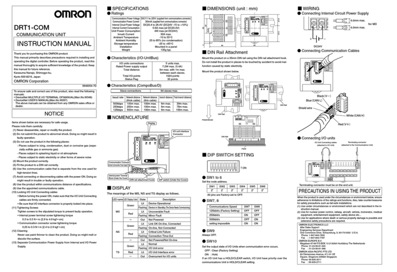
Omron DRT1-COM User manual

Omron
Omron Sysmac E3X-ECT User manual

Omron
Omron ZS-CRT User manual