Flexible Safety Unit
Type G9SX-EX401-□
Type G9SX-EX041-T-□
USER'S MANUAL
Precaution for Safe Use
Indicates a potentially hazardous
situation which, if not avoided, will
resultin minor or moderate injury, or
may result in serious injury or death.
Additionally there may be significant
property damage.
Meanings of Signal Words
The following signal words are used in this manual.
Alert Statements
Serious injury may possibly occur due to breakdown
of safety outputs.
Do not connect loads beyond the rated value to the
safety outputs.
Serious injury may possibly occur due to loss of
required safety functions.
Wire G9SX properly so that supply voltages or
voltages for loads do NOT touch the safety inputs
accidentally or unintentionally.
Serious injury may possibly occur due to damages of
safety inputs.
Apply protection circuitry against back electromotive
force in case connecting inductiveloads to safety
outputs.
Serious injury may possibly occur due to loss of
safety functions.
Use devices appropriate for the application andthe
condition where G9SX is used.
Indicates prohibited actions
Meaning of Alert Symbols
The following alert symbols are used in this manual.
Indicates mandatory actions
WARNING
WARNING
(1) Use G9SX within a enclosure with IP54 protection or higher of
IEC/EN60529.
(2) Incorrect wiring may lead to loss of safety function. Wireconductors
correctly and verify the operation of G9SX before commissioning the
system in which G9SX is incorporated.
(3) Do not apply DC voltages exceeding the rated voltages, norany AC
voltages to G9SX.
(4) Use DC supply satisfying requirements below to prevent electric shock.
- DC power supply with double or reinforced insulation, for example,
according to IED/EN60950 or EN50178 or a tranceformer
according to IEC/EN61558.
- DC supply used satisfies the requirement for class 2 circuits or
limited voltage/current circuit stated in UL 508.
(5) Auxiliary error output is NOT safety outputs.
Do not use auxiliary error output as any safety output.
Such incorrect use causes loss of safety function of G9SX andits
relevant system.
(6) After installation of G9SX, qualified personnel should confirm the
installation, and should conduct test operations and maintenance.
The qualified personnel should be qualified and authorized to secure
the safety on each phases of design, installation, running,
maintenance and disposal of system.
(7) A person in charge, who is familiar to the machine in which G9SX is to
be installed, should conduct and verify the installation.
(8) Turn OFF the signal to Safety input or Logical AND connection input
every 24hours and make sure G9SX operates without faults by
checking the state of the ERR indicator.
(9) Do not dismantle, repair, or modify G9SX. It may lead to loss of its
safety functions.
(10) Use only appropriate components or devices complying with relevant
safety standards corresponding to the required level of safety
categories.
Conformity to requirements of safety category is determined as an
entire system.
It is recommended to consult a certification body regarding
assessment of conformity to the required safety level.
(11) OMRON shall not be responsible for conformity with any safety
standards regarding to customer's entire system.
(12) Disconnect G9SX from power supply when wiring, to prevent electric
shock or unexpected operation.
(13) Be cautious not to have your fingers caught when attaching terminal
sockets to the plugs on G9SX.
(14) The lifetime of G9SX depends on the conditions of switching of its
outputs. Be sure to conduct its test operation under actual operating
conditions in advance and use it within appropriate switching cycles
(15) Do not use in combustible gases or explosive gases. Arcs or heat
generated by switching elements of G9SX can lead to fire or
explosion.
Precaution for Safe Use
(1) Handle with care
Do not drop G9SX to the ground or expose to excessive vibration or
mechanical shocks. G9SX may be damaged and may not function
properly.
(2) Conditions of storage
Do not store in such conditions stated below.
1) In direct sunlight
2) At ambient temperatures out of the range of -10 to 55℃
3) At relative humidity out of the range of 25 to 85% or under such
temperature change that causes condensation.
4) In corrosive or combustible gases
5) With vibration or mechanical shocks out of the rated values.
6) Under splashing of water, oil, chemicals
7) In the atmosphere containing dusts, saline or metal powder
G9SX may be damaged and may not function properly.
(3) Mounting
Mount G9SX to DIN rails with attachments (TYPE PFP-M, not
incorporated to this product), not to drop out of rails by vibration etc.
especially when the length of DIN railing is short compared to the
widths of G9SX.
Precautions for Correct Use
(4) Following spacing around G9SX should be available to apply rated
current to outputs of G9SX and for enough ventilation and wiring:
a) At least 25 mm beside side faces of G9SX.
b) At least 50 mm above top face of G9SX and below bottom face of
G9SX.
c) At least 25 mm between side face of Advanced unit (G9SX-
AD322-□-□) and side face of Expansion unit (G9SX-EX401-□or
G9SX-EX041-T-□).
(5) Wiring
1) For model G9SX-□
Use the following to wire to G9SX-□.
- Solid wire: 0.2 to 2.5mm
2
AWG24 to AWG12
- Stranded wire (Flexible wire): 0.2 to 2.5mm
2
AWG24 to AWG12
Strip the cover of wire no longer than 7mm.
2) For model G9SX-□-RT (with screw terminals)
Tighten each screw with a specified torque of 0.5 to 0.6N・m, or
the G9SX-□may malfunction or generate heat.
(6) When connecting Expansion Units to Advanced Unit
(TYPE G9SX- AD322-□-□):
1) Follow the procedure below:
a) Remove the termination connector from the receptacle on
Advanced Unit (TYPE G9SX-AD322-□-□),
b) Insert the head of the connecting cable of Expansion Unit to the
receptacle on the Advanced Unit
c) Set the termination connector to the receptacle on the
Expansion Unit at the end position. When Advanced Unit is used
as without expansion units, leave the terminination connector set
on the Advanced Unit.
2) Do not remove the termination connecter while the system is
operating.
3) Before applying supply voltage, confirm that the connecting sockets
and plugs are locked firmly.
4) All of the Expansion Units should be supplied with its specified
voltages within 10s after the connected Advanced Unit is supplied
with voltage.
Otherwise, Advanced Unit detects the power-supply error for the
Expansion Units.
(7) Start entire system after more than 5s have passed since applying
supply voltage to all G9SXs in the system.
(8) G9SX may malfunction due to electro-magnetic disturbances.
Be sure to connect the terminal A2 to ground.
(9) Devices connected to G9SX may operate unexpectedly.
When replacing G9SX, disconnect it from power supply.
(10) Adhesion of solvent such as alcohol, thinner, trichloroethane or
gasoline on the product should be avoided. Such solvents make the
marking on G9SX illegible and cause deterioration of parts.
(11) Do NOT mix AC load and DC load to be switched in one G9SX-EX-□.
When switching of both AC load and DC load is ncessary, connect
more than two G9SX-EX-□and use each unit for AC load and DC
load exclusively.
(12)This is a class A product. In residential areas it may cause radio
interference, in which case the user may be required to take adequate
measures to reduce interference.
25mm min. 25mm min.
ED
PWR
A2X2
44342414
A1
33 4313 23
No.
G9SX
-
EX
24VDC
ED
PWR
A2X2
44342414
A1
33 4313 23
No.
G9SX
-
EX
24VDC
G9SX
-
BC202
24VDC
No.
T1 T2
FB
ERREI
PWB
L2L1S24S14
A2X2T22T21
A1X1T12T11
Y1T32 T33T31
No.
OFF-DELAY
0.5
0.4
0.3
0.2 15107
5
4
3
2
1.5
1
0.6
0.7
0
S54S44S34S24S14 L1
A2T42T41T22T21
A1X2X1Y1T12T11
T33T31
T1
ERR
EI
AND
FB
ED
T2
PWR
T32
G9SX
-
AD322
-
T15
24VDC
50mm min.
50mm min.
Appearance and Explanation of Each Parts
1
TYPE G9SX-EX041-T-□TYPE G9SX-EX401-□
(Expansion Unit) (Expansion Unit: Off-delay Model)
TYPE G9SX-EX041-T-□TYPE G9SX-EX401-□
(Expansion Unit) (Expansion Unit: Off-delay Model)
EI
PWR
A2X2
44342414
A1
33 4313 23
No.
G9SX
-
EX401
24VDC
ED
PWR
A2X2
44342414
A1
33 4313 23
No.
G9SX
-
EX041-T
24VDC
Power Supply Input
terminal (+)
Power Supply Input
terminal (-)
Auxiliary Error
output terminal
Auxiliary Error
output terminal
Safety relay contact
output terminals Safety off-delay
relay contact
output terminals
Safety off-delay
relay contact
output terminals
Safety relay contact
output terminals
43332313
PWR
44
A2
14 24
A1
34
X2
EI
ERR
Terminal arrangement and LED indicators
Power Supply Input
terminal (+) Power Supply Input
terminal (-)
LED Indicators
Connect the power supply
plus to the A1 terminal.
Connect the power supply
minus to the A2 terminal.
The outputs synchronize
with safety outputs of
Advanced unit.
Outputs during error
indicator is lighting up.
Wiring of inputs and outputs
Signal
name
Safety
relay
output
Power
supply
input
Terminal
name
13-14,
23-24,
33-34,
43-44
A1,
A2
Auxiliary
error
output
X2
Wiring
Description of operation
The input terminals
for power supply.
Connect the power
source to A1 and A2
terminals. Keep these outputs Open
when NOT used.
Keep these outputs Open
when NOT used.
TYPE G9SX-EX401-□/ TYPE G9SX-EX041-T-□
Internal Connection
2
A2 X2
Power
supply
circuit
Auxiliary
outputs
control
Safety
outpus
control
A1
K1
13 23 33 43
14 24 34 44
K2
Exp.
sig.
IN
Exp.
sig.
OUT
*1 Internal power supply circut is not isolated.
*2 Relay outputs are isolated
*1 *2
Dimensions
3
*Note2 *Note2
100 max.
(6) (6)
115 max.
23 max.
*Note1 Above outline drawing is for -RC terminal type.
*Note2 For -RC terminal type only.
(22.5)*
* Typical dimension
Ratings and Specifications
4
Ratings
Endurance
Outputs
Rated supply voltage
Electrical
endurance 5,000,000 cycles Min.
(Switching frequency: 7,200 cycles/hour)
Isolation specification
Item
Note1: Not including Operating time or Response time of G9SX-AD322-□-□(Advanced Unit).
Note2: Both G9SX-EX401-□(Expansion Unit) and G9SX-EX401-T-□(Expansion Unit: Off-delay Model) can be connected in the same system.
Note3: Not including accuracy of release time of the relays.
Note4: Off-delay time setting is applied from Advanced Unit.
PNP transistor output,
Load current: 100mA Max.
Auxiliary output
Specifications and Performance
Item
Over voltage category (IEC/EN 60664-1) G9SX-EX401-□G9SX-EX041-T-□
II (safety relay outputs 13 to 43, 14 to 44 : III)
Operating time (OFF to ON state) (See Note1) 30ms Max.
10ms Max.
Maximum number of connectable units (See Note2) 5 units Max.
Accuracy of Off-delay time (See Note3) -Within plus or minus 5% of the set value (See Note4)
G9SX-EX401-□/G9SX-EX041-T-□
24VDC
-15% to +10% of rated supply voltage
2W Max.
250VAC 3A / 30VDC 3A
(resistive load)
3A
250VAC , 125VDC
Vibration resistance Frequency: 10 to 55 to 10 Hz, Amplitude: 0.375mm half amplitude (0.75mm double amplitude)
Mechanical shock resistance 300 m/s
2
(destruction), 100m/s
2
(malfunction)
Ambient temperature -10 to +55℃(No freezing or condensation)
Ambient humidity 25〜85%RH
Terminal tightening 0.5 Nm (Applicable only to TYPE G9SX-□-RT:screw terminal model)
Weight Approx. 145 g
100Mohm Min. (by 500VDC megger)
Insulation resistance
Dielectric strength 1200VAC 1min
2200VAC 1min
Between all terminals connected together and DIN rail
Between different poles of outputs
Between Safety relay outputs connected together
and other terminals connected together.
Between all terminals connected together and DIN rail
Between different poles of outputs
Between Safety relay outputs connected together
and other terminals connected together.
Response time (ON to OFF state) (See Note1)
O-delay time
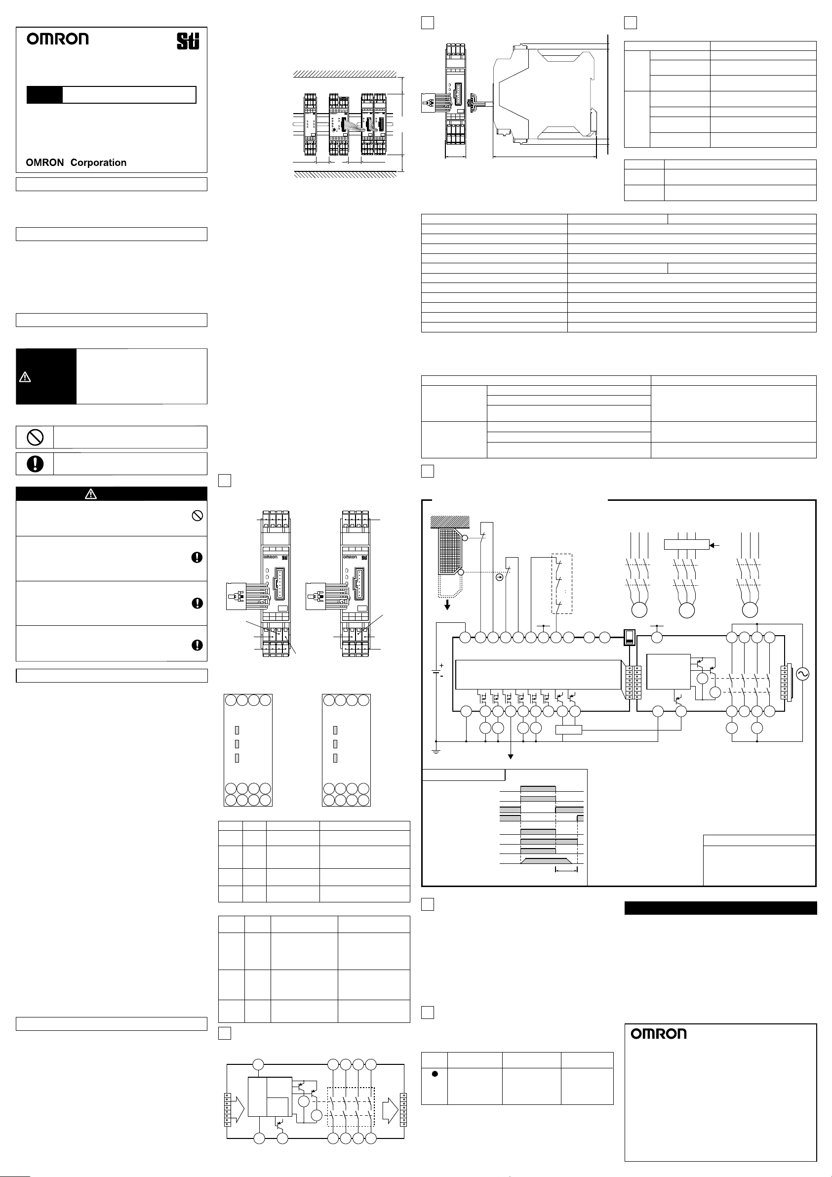
KM1,KM2 NC contact
KM3〜KM6 NC contact
KM1,KM2 NO contact
KM3〜KM6 NO contact
Operation command
Rotation of motor
S14
A2
S24 S34 S44 S54
L1 X1 X2
T11
A1
T12 T21 T22 T31 T32 T33
Y1
T41 T42
KM2
KM6
KM1
+24V +24V
Feedback Loop
+24V
KM1 KM5 KM6
KM2 KM3 KM4
Limit switch S2
Safety limit switch S1
Operation
command
M1
KM2
KM1
M3
KM6
KM5
M2
KM4
KM3
Motor controller
OFF
AND
PLC etc.
Timing chart
open
23
24
11
12
S2
S1
GND
S1
S2
KM1〜KM6
M1〜M3
:Safety limit switch
:Limit switch
:Contactor
:3-phase motor
Devices
G9SX-AD322-□G9SX-EX041-T
Control circuit Control
circuit
NC NC NC
A2 X2
A1
K1
13 23 33 43
14 24 34 44
K2
Note1: This example is corresponding to category 4(EN 954-1)
S34
Examples of application
5
Application and timing chart
Category of EN 954-1, ISO13849-1
6
In the condition shown in '5.Examples of Application' on this paper,
G9SX can be used for the corresponding categories up tocategory
4 per EN954-1 and performance level(PL) up to e per ISO13849-1.
This does NOT mean that G9SX can always be used for required
category under all the similar conditions and situations.
Conformity to the categories must be assessed as a whole system.
When using G9SX for safety categories, be sure to confirm the
conformity as a whole system.
For use of Safety category 4, fuses of 3.15A current rating should be
connected to safety relay outputs to prevent welding of the contacts.
Fault Detection
7
ERR
indicator
Light up
Conditions Expected causes
of the faults
Replace with a
new product.
When G9SX detects a fault, ERR indicator lights up to show the
information of the fault.
Check and take needed measures referring to the following table.
And then apply supply voltage to G9SX.
English
Suitability for Use
OMRON shall not be responsible for conformity with any
standards, codes, or regulations that apply to the combination of
the products in the customer's application or use of the product.
Take all necessary steps to determine the suitability of the
product for the systems, machines, and equipment with which it
will be used. Know and observe all prohibitions of use applicable
to this product.
NEVER USE THE PRODUCTS FOR AN APPLICATION INVOLVING
SERIOUS RISK TO LIFE OR PROPERTY WITHOUT ENSURING THAT
THE SYSTEM AS A WHOLE HAS BEEN DESIGNED TO ADDRESS THE
RISKS, AND THAT THE OMRON PRODUCT IS PROPERLY RATED AND
INSTALLED FOR THE INTENDED USE WITHIN THE OVERALL
EQUIPMENT OR SYSTEM.
EU Declaration of Conformity
Standards
OMRON declares that G9SX is in conformity with the
requirements of the following EU Directives:
- EMC Directive 2004/108/EC
- Machinery Directive 2006/42/EC
G9SX is designed and manufactured in accordance with the
following standards:
- EN954-1 Category 4,
- EN ISO13849-1:2008 Category 4 PL e,
- IEC/EN61508 SIL3,
- IEC/EN61000-6-2, - IEC/EN61000-6-4,
- UL508, - UL1998,
- CAN/CSA C22.2 No.142
Original instructions
OMRON EUROPE B.V. (Importer in EU)
Wegalaan 67-69, NL-2132 JD Hoofddorp THE NETHERLANDS
PHONE 31-2356-81-300 FAX 31-2356-81-388
OMRON SCIENTIFIC TECHNOLOGIES INC.
6550 Dumbarton Circle, Fremont CA 94555-3605 U.S.A
PHONE 1-510-608-3400 FAX 1-510-744-1442
OMRON ASIA PACIFIC PTE. LTD.
438A Alexandra Road # 05-05/08,
Alexandra Technopark Singapore 119967 SINGAPORE
PHONE 65-6-835-3011 FAX 65-6-835-2711
Note: Specications subject to change without notice.
OMRON Corporation (Manufacturer)
Shiokoji Horikawa, Shimogyo-ku, Kyoto, 600-8530 JAPAN
OMRON (CHINA) CO., LTD.
Room 2211, Bank of China Tower, 200 Yin Cheng Zhong Road,
PuDong New Area, Shanghai, 200120, China
PHONE 86-21-5037-2222 FAX 86-21-5037-2200
Thank you for purchasing G9SX Flexible Safety Unit.
Please read and understand this manual before using the products.
Keep this manual ready to use whenever needed.
Only qualified person trained in professional electrical technique
should handle G9SX.
Please consult your OMRON representative if you have any
questions or comments.
Make sure that information written in this document are delivered to
the final user of the product.
Marking FunctionNameColor
PWR Lights up while power is supplied.
Power Supply
Indicator
Green
ERR Lights up when an error occurs.
For details refer to
'7. Fault Detection'.
Error IndicatorRed
EI Lights up while Safety relay
outputs are in ON-state.
Safety Output
Indicator
Orange
ED Lights up while Off-delayed
relay outputs are in ON-state.
Off-delayed Safety
Output Indicator
Orange
(Expansion Unit / Expansion Unit o-delay model)
43332313
PWR
44
A2
14 24
A1
34
X2
ED
ERR
Item
Power
input Operating voltage
range
Rated carry current
Rated power
consumption
Maximum switching
voltage
Rated load
G9SX-EX401-□/G9SX-EX041-T-□
100,000 cycles Min.
(Rated load, Switching frequency: 1,800 cycles/hour)
Item
Mechanical
endurance
G9SX-EX401-□/G9SX-EX041-T-□
G9SX-AD322-□(24VDC) + G9SX-EX041-T (24VDC)
(2-channel safety limit switch inputs / Auto reset)
Faults involved with
Safety relay outputs
of Expansion Units
Expected causes
of the faults
1) Welding of relay
contacts
2) Failures of the
parts of the
internal circuits
2139837-8B


