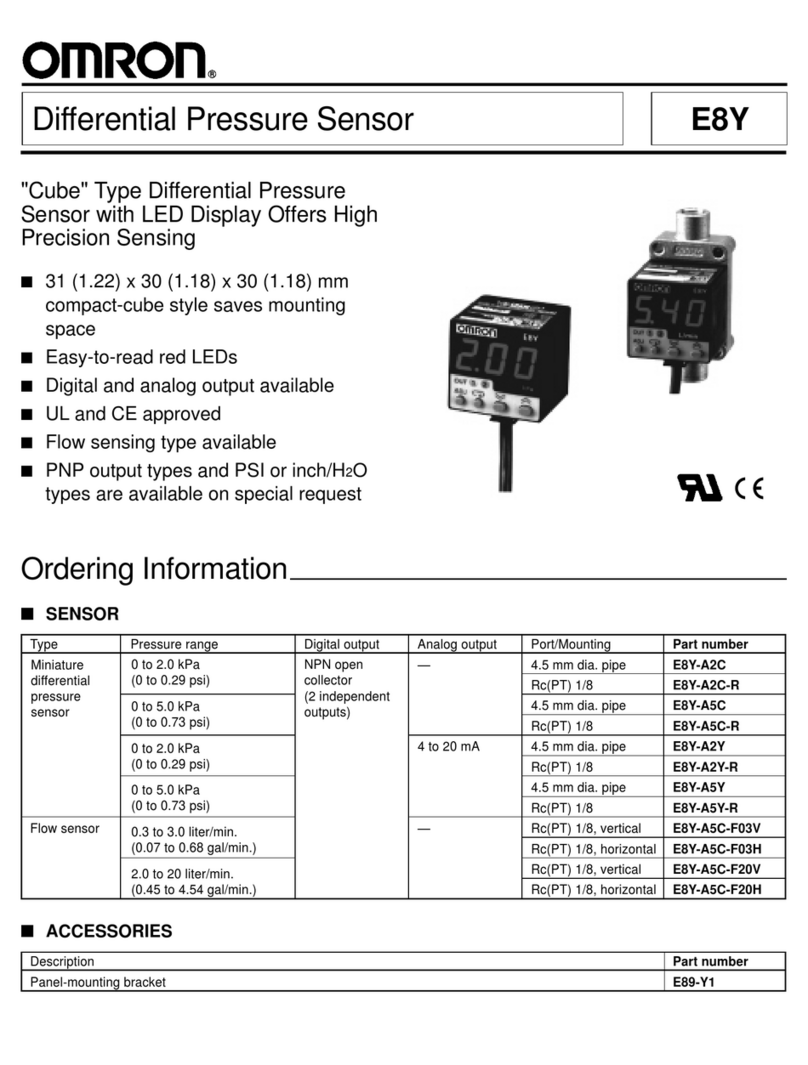
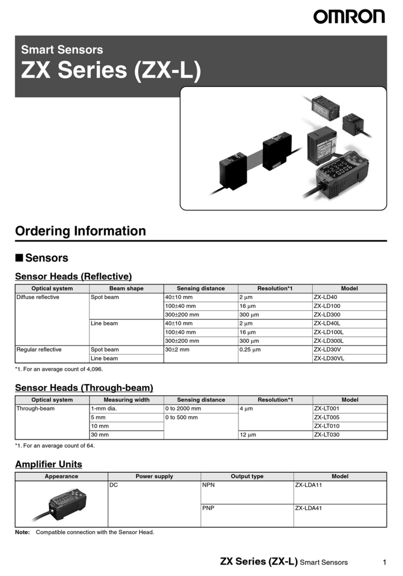
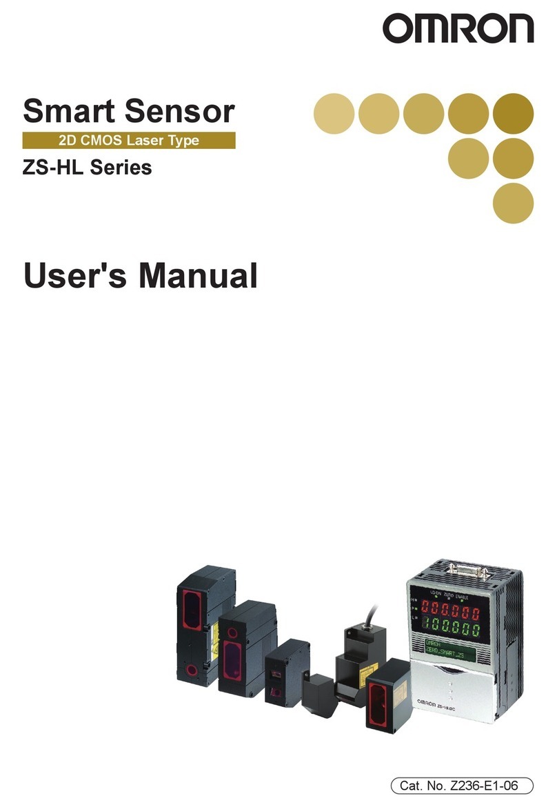
Omron MS2800 User manual
Other Omron Security Sensor manuals
Omron
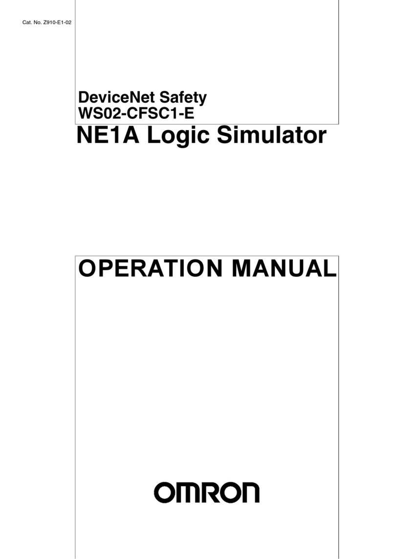
Omron WS02-CFSC1-E User manual
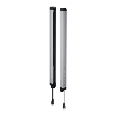
Omron
Omron F3SG-4RA****-25-01TS Series Operating and maintenance instructions
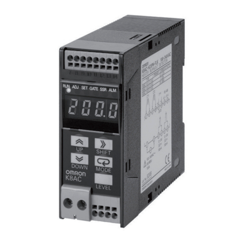
Omron
Omron K8AC-H Series User manual
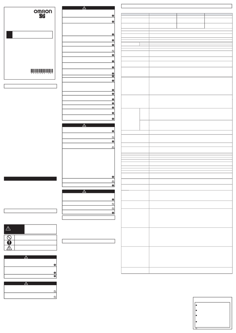
Omron
Omron Sti F3SJ-AM P Series User manual
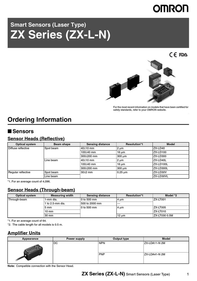
Omron
Omron ZX-L-N User manual
Omron
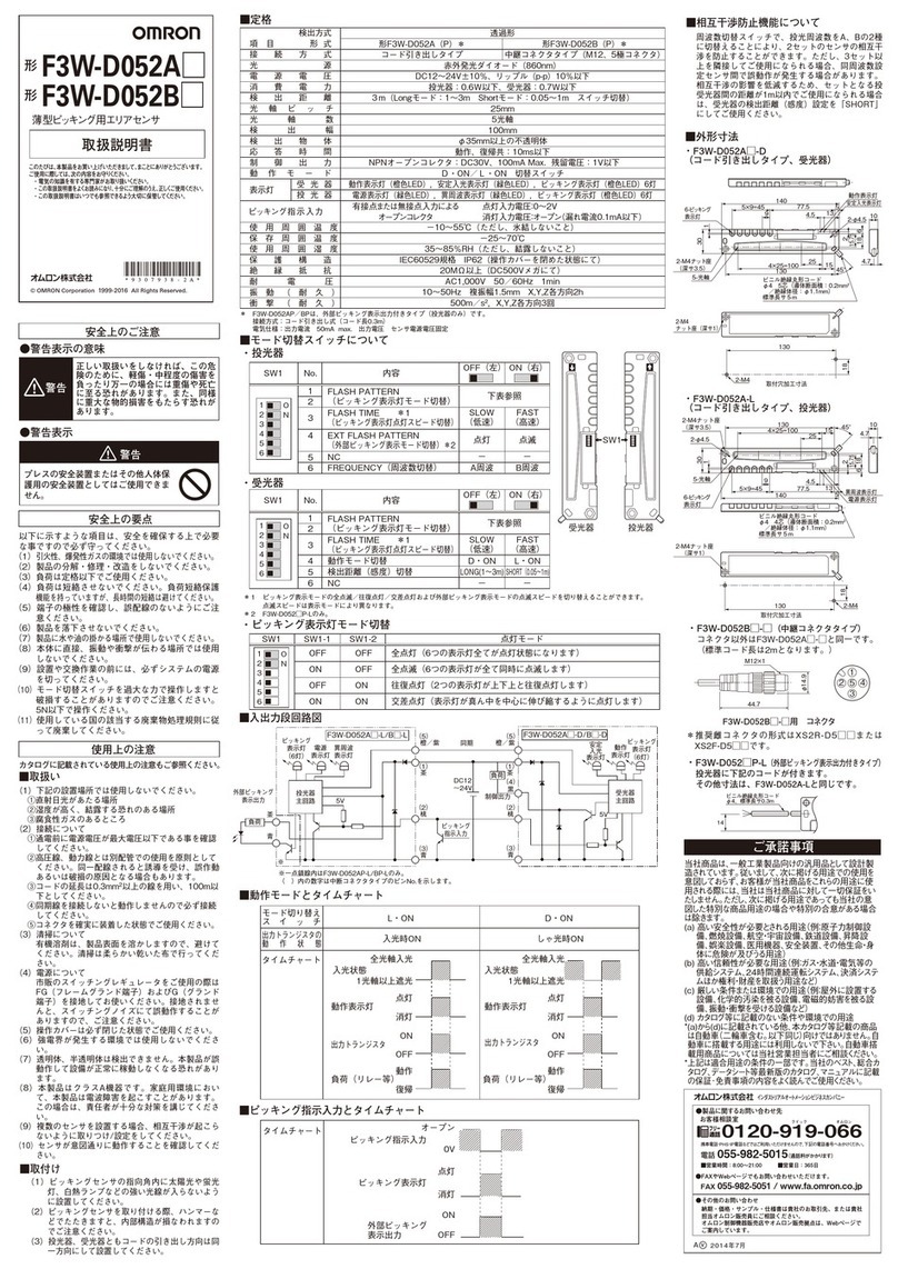
Omron F3W-D052A User manual
Omron
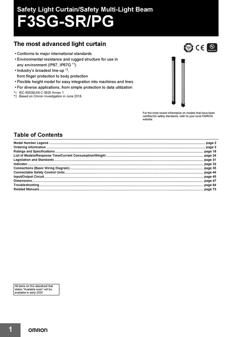
Omron F3SG-SR/PG User manual
Omron
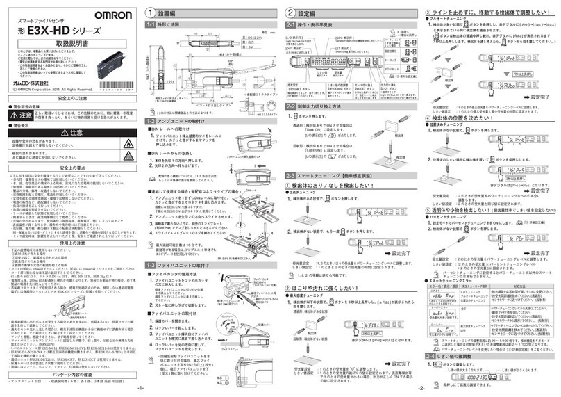
Omron E3X-HD11 User manual
Omron
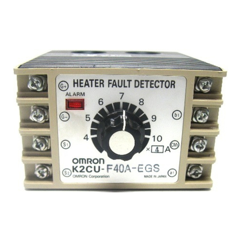
Omron K2CU - User manual
Omron
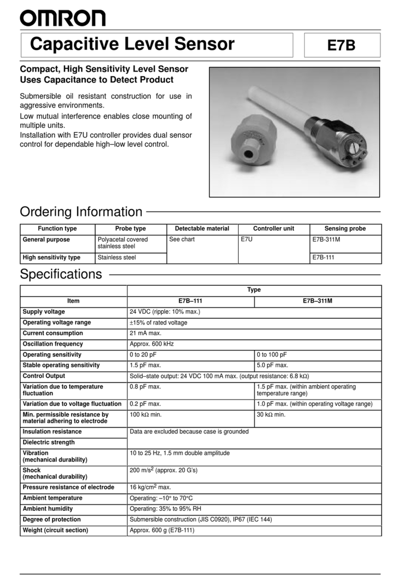
Omron E7B User manual
Omron
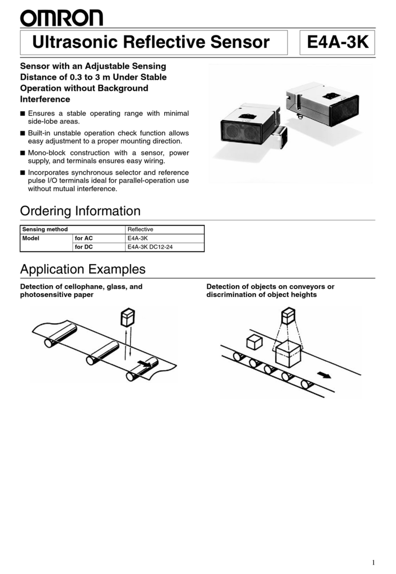
Omron E4A-3K User manual
Omron
Omron F3SP-U5P-TGR User manual
Omron
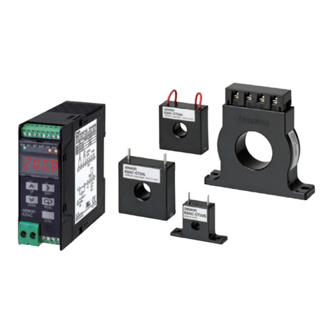
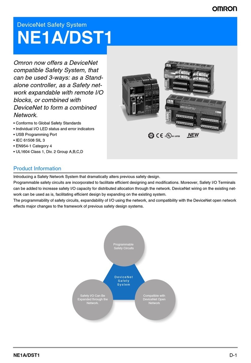
Omron K8AC-H Series User manual
Omron
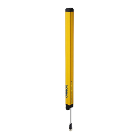
Omron DST1 Series User manual
Omron
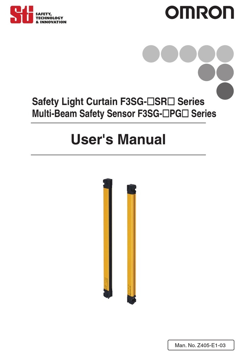
Omron F3SG-2RE0430P30 User manual
Omron
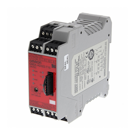
Omron F3SGPGA-A User manual
Omron
Omron G9SX Series User manual
Omron
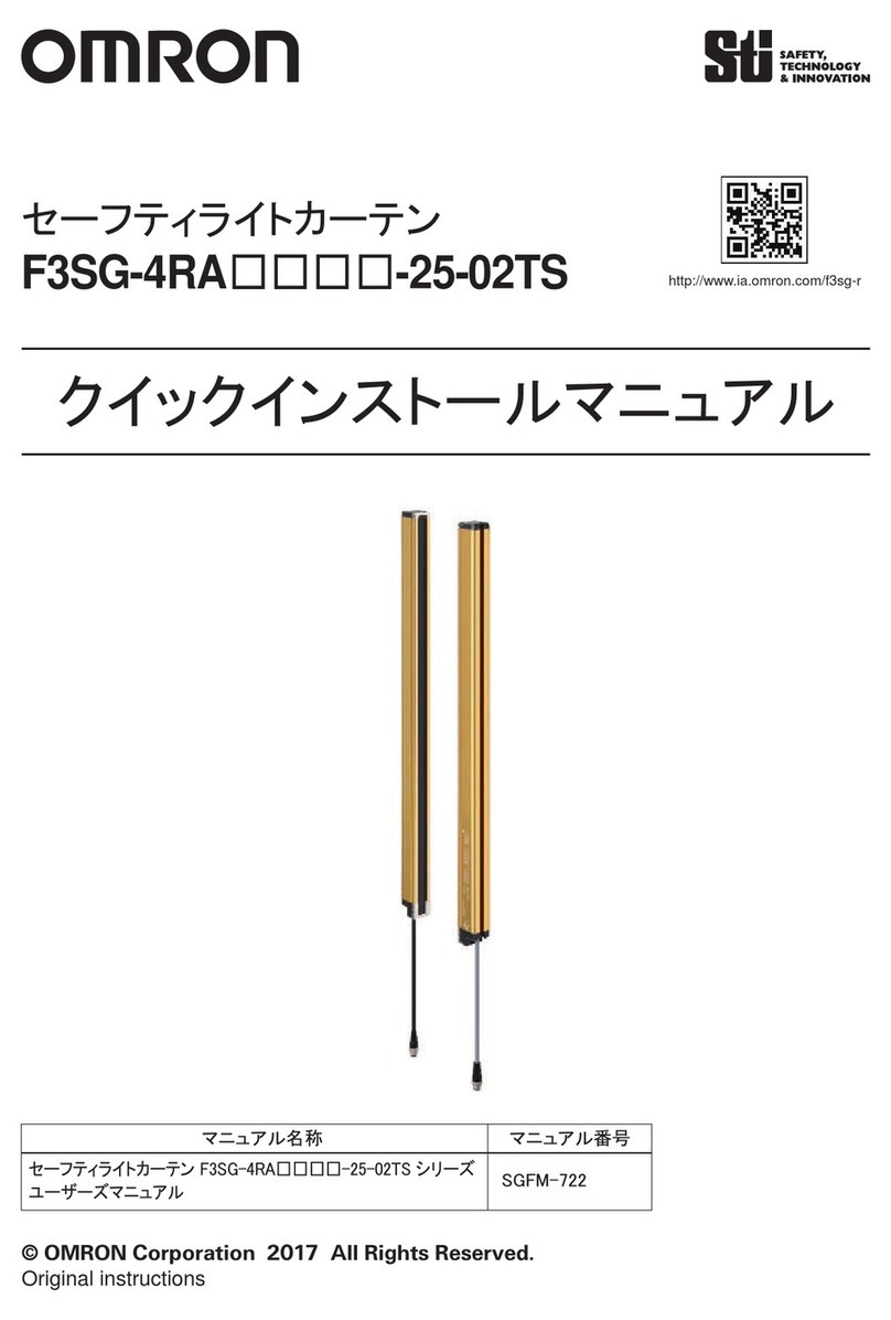
Omron F3SG-4RA****-25-02TS series Operating and maintenance instructions
Omron
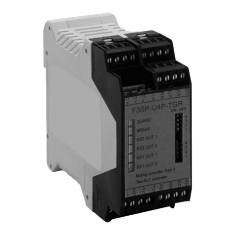
Omron F3SP-U4P-TGR User manual
Omron
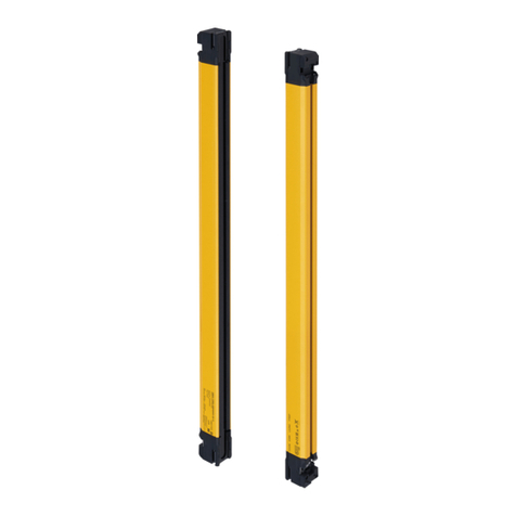
Omron F3SG-SRB Series User manual
Popular Security Sensor manuals by other brands

Honeywell Home
Honeywell Home PROSiXCOCN Installation and setup guide

Duevi
Duevi SIRPZ-RB-868 Operation

RKI
RKI 65-2483RK Operator's manual

Nortech
Nortech PD160 Enhanced Series user manual

Agilent Technologies
Agilent Technologies G8610 Series Quick reference card

Shinko
Shinko SE2EA-1-0-0 instruction manual

Det-Tronics
Det-Tronics X Series instructions

ACR Electronics
ACR Electronics COBHAM RCL-300A Product support manual

TOOLCRAFT
TOOLCRAFT 1712612 operating instructions

Elkron
Elkron IM600 Installation, programming and functions manual

Bosch
Bosch WEU PDO 6 Original instructions

THORLABS
THORLABS PDA10JT user guide
