manuals.online logo
Brands
  1. Home
  2. •
  3. Brands
  4. •
  5. Omron
  6. •
  7. Switch
  8. •
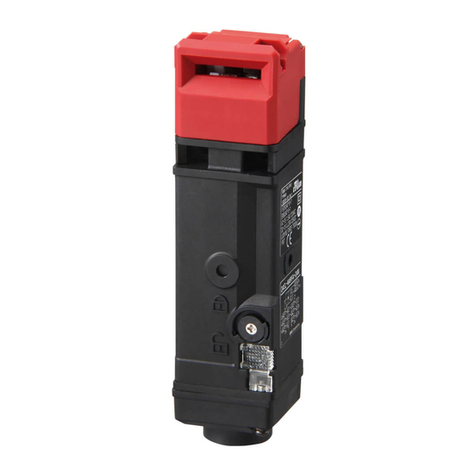
  9. Omron D4JL-SK40 User manual

Omron D4JL-SK40 User manual

This manual suits for next models

82

Other Omron Switch manuals

Omron CM-S221 User manual

Omron

Omron CM-S221 User manual

Omron D41D User manual

Omron

Omron D41D User manual

Omron H2F - User manual

Omron

Omron H2F - User manual

Omron C2UW-L Series User manual

Omron

Omron C2UW-L Series User manual

Omron ZC-55 - User manual

Omron

Omron ZC-55 - User manual

Omron E3L-2RC4 User manual

Omron

Omron E3L-2RC4 User manual

Omron D4BL - User manual

Omron

Omron D4BL - User manual

Omron D4NH - User manual

Omron

Omron D4NH - User manual

Omron C2UW-L DA Series User manual

Omron

Omron C2UW-L DA Series User manual

Omron D2MQ Series User manual

Omron

Omron D2MQ Series User manual

Omron 61F-GP-N User manual

Omron

Omron 61F-GP-N User manual

Omron D4NL - User manual

Omron

Omron D4NL - User manual

Omron H5S - User manual

Omron

Omron H5S - User manual

Omron D2JW-011 User manual

Omron

Omron D2JW-011 User manual

Omron A22NN User manual

Omron

Omron A22NN User manual

Omron D4GL-1AFA-A4 User manual

Omron

Omron D4GL-1AFA-A4 User manual

Omron B3F User manual

Omron

Omron B3F User manual

Omron WLM - User manual

Omron

Omron WLM - User manual

Omron D4N Series User manual

Omron

Omron D4N Series User manual

Omron D4NL-1AFA-B User manual

Omron

Omron D4NL-1AFA-B User manual

Omron A8GS-T Series User manual

Omron

Omron A8GS-T Series User manual

Omron D4SL-N Series User manual

Omron

Omron D4SL-N Series User manual

Omron D4B-N - User manual

Omron

Omron D4B-N - User manual

Omron A165E - User manual

Omron

Omron A165E - User manual

Popular Switch manuals by other brands

SMC Networks SMC6224M Technical specifications

SMC Networks

SMC Networks SMC6224M Technical specifications

Aeotec ZWA003-S operating manual

Aeotec

Aeotec ZWA003-S operating manual

TRENDnet TK-209i Quick installation guide

TRENDnet

TRENDnet TK-209i Quick installation guide

Planet FGSW-2022VHP user manual

Planet

Planet FGSW-2022VHP user manual

Avocent AutoView 2000  AV2000BC AV2000BC Installer/user guide

Avocent

Avocent AutoView 2000 AV2000BC AV2000BC Installer/user guide

Moxa Technologies PT-7728 Series user manual

Moxa Technologies

Moxa Technologies PT-7728 Series user manual

Intos Electronic inLine 35392I operating instructions

Intos Electronic

Intos Electronic inLine 35392I operating instructions

Cisco Catalyst 3560-X-24T Technical specifications

Cisco

Cisco Catalyst 3560-X-24T Technical specifications

Asante IntraCore IC3648 Specifications

Asante

Asante IntraCore IC3648 Specifications

Siemens SIRIUS 3SE7310-1AE Series Original operating instructions

Siemens

Siemens SIRIUS 3SE7310-1AE Series Original operating instructions

Edge-Core DCS520 quick start guide

Edge-Core

Edge-Core DCS520 quick start guide

RGBLE S00203 user manual

RGBLE

RGBLE S00203 user manual

Thrustmaster FLIGHT SIMULATOR X quick guide

Thrustmaster

Thrustmaster FLIGHT SIMULATOR X quick guide

Southwire SURGE GUARD 41390 RVC troubleshooting guide

Southwire

Southwire SURGE GUARD 41390 RVC troubleshooting guide

Buhler Nivotemp NT 61 Brief instructions

Buhler

Buhler Nivotemp NT 61 Brief instructions

Kramer VS-41HDCP user manual

Kramer

Kramer VS-41HDCP user manual

Techly IDATA AU-270 user manual

Techly

Techly IDATA AU-270 user manual

Belkin F1U109 user manual

Belkin

Belkin F1U109 user manual

manuals.online logo
manuals.online logoBrands
  • About & Mission
  • Contact us
  • Privacy Policy
  • Terms and Conditions

Copyright 2025 Manuals.Online. All Rights Reserved.

CSM_D4JL_D4JL-SK40_DS_E_7_2
1
Guard Lock Safety-door Switch/Slide key
D4JL/D4JL-SK40
Holding Force of 3,000 N
• Two safety circuits and two monitor contacts provide an
array of monitoring patterns.
• Standard gold-clad contacts enable use with ordinary loads
and microloads.
• Models with trapped keys prevent workers from being locked
in hazardous work areas.
• Models with rear release buttons allow people to unlock the
Switch and escape if they are locked into hazardous areas.
• IP67 degree of protection
Features
Plastic Guard Lock Safety-door Switches
Rank Among the Strongest in the World
A holding force of 3,000 N makes these Switches suitable for large,
heavy doors.
Two Safety Circuits and Two Monitor
Contacts
The D4JL has two safety circuits. It also has two contacts to
separately monitor the open/closed status of the door and the status
of the lock.
Wide variations to protect workers who
enter hazardous areas.
•Models with Trapped Keys (mechanical lock models only)
As long as a person has the trapped key when he enters a
hazardous area, he does not have to worry about somebody
locking the door and trapping him inside.
The door can be opened only by supplying power to the solenoid
and then turning the trapped key to unlock the D4JL.
There are thirty different types of trapped keys available for use in
applications with adjacent hazardous areas.
•Models with Rear Release Buttons
A rear release button allows the door to be unlocked from inside a
hazardous area in an emergency.
•Special Slide Key
A special Slide Key shortens the lead time for mounting design.
The padlock that can be attached to the disable-prevention cover
prevents other workers from restarting machines.
(See page 5 for details.)
Be sure to read the “Safety Precautions” on page 24.
Guard Lock Safety-door Switch
Slide keys
For the most recent information on models that have been certified for
safety standards, refer to your OMRON website.
41
51 52
63 64
42
Lock Monitor Switch Door Open/Closed
Detection Switch
Monitoring
the door lock
Monitoring the open/
closed status of the door
11 12 To safety circuit
To safety circuit
To control circuit
33 34
2221
Rear release button Rear release button
D4JL-@@@A-@8-01-SJD4JL-@@@A-06
D4JL/D4JL-SK40
2
Model Number Structure
Model Number Legend
Switches (Standard type)
1. Conduit Size
2: G1/2
4: M20
2. Built-in Switch
N: 2NC/1NO + 2NC/1NO (slow-action contacts)
P: 2NC/1NO + 3NC (slow-action contacts)
Q: 3NC + 2NC/1NO (slow-action contacts)
R: 3NC + 3NC (slow-action contacts)
3. Head Material
F: Plastic
4. Door Lock and Release
A: Mechanical lock/24 VDC solenoid release
G: 24 VDC Solenoid lock/Mechanical release
5. Indicator
C: 24 VDC (green LED indicator)
D: 24 VDC (orange LED indicator)
6. Release Key Type
5: Special release key *1
6: Special release key + rear release button *1
7: Trapped key
7. Trapped Key Type
01 to 30: 30 types *2
Note:
A 24 VDC solenoid lock cannot be combined with a trapped key.
A 24 VDC solenoid lock cannot be combined with a special
release key and rear release button.
*1. Release keys are provided.
*2. Thirty types of trapped keys can be manufactured. Specify the
trapped key type in numerical order starting from 01 when
ordering.
Switches (Connector type)
1. Conduit Size
2: G1/2
2. Built-in Switch
R: 3NC + 3NC (slow-action contacts)
3. Head Material
F: Plastic
4. Door Lock and Release
A: Mechanical lock/24 VDC solenoid release
5. Indicator
C: 24 VDC (green LED indicator)
D: 24 VDC (orange LED indicator)
6. Release Key Type
5: Standard release key
7. Connection Method
N: Connector type
8. Cover Mounting Screws
T: Standard screws
X: Special screws
Note: For more information about connector types, contact your
OMRON sales representative.
Switches (Trapped key + Rear release buttons type)
1. Conduit Size
2: G1/2
4: M20
2. Built-in Switch
N: 2NC/1NO + 2NC/1NO (slow-action contacts)
P: 2NC/1NO + 3NC (slow-action contacts)
Q: 3NC + 2NC/1NO (slow-action contacts)
R: 3NC + 3NC (slow-action contacts)
3. Head Material
F: Plastic
4. Door Lock and Release
A: Mechanical lock/24 VDC solenoid release
5. Indicator
C: 24 VDC (green LED indicator)
D: 24 VDC (orange LED indicator)
6. Release Key Type
8: Trapped key + Rear release buttons
7. Trapped Key Type
01: 1 type
Operation Keys
1. Operation Key Type
1: Horizontal mounting
2: Vertical mounting
3: Adjustable mounting (horizontal)
1 2 3 4 5 6 7
D4JL-@@@@-@@-@@
1 2 3 4 5 6 7 8
D4JL-2RFA-D5N-X
1 2 3 4 5 6 7
D4JL-@@@@-@@-@@-SJ
1
D4JL-K@
3
D4JL/D4JL-SK40
Ordering Information
Switches (Operation Keys are sold separately.)
Consult with your OMRON representative when ordering any models that are not listed in this table.
Standard Models
Models with Rear Release Buttons
*Models with Korean S-mark certification.
Release key type Indicator Lock and release types
Contact configuration
(door open/closed detection switch and
lock monitor switch contacts)
Conduit opening Model
Special release key
Green
Mechanical lock
Solenoid release
2NC/1NO+2NC/1NO G1/2 D4JL-2NFA-C5
M20 D4JL-4NFA-C5
2NC/1NO+3NC G1/2 D4JL-2PFA-C5
M20 D4JL-4PFA-C5
3NC+2NC/1NO G1/2 D4JL-2QFA-C5
M20 D4JL-4QFA-C5
3NC+3NC G1/2 D4JL-2RFA-C5
M20 D4JL-4RFA-C5
Solenoid lock
Mechanical release
2NC/1NO+2NC/1NO G1/2 D4JL-2NFG-C5
M20 D4JL-4NFG-C5
2NC/1NO+3NC G1/2 D4JL-2PFG-C5
M20 D4JL-4PFG-C5
3NC+2NC/1NO G1/2 D4JL-2QFG-C5
M20 D4JL-4QFG-C5
3NC+3NC G1/2 D4JL-2RFG-C5
M20 D4JL-4RFG-C5
Orange
Mechanical lock
Solenoid release
2NC/1NO+2NC/1NO G1/2 D4JL-2NFA-D5
M20 D4JL-4NFA-D5
2NC/1NO+3NC G1/2 D4JL-2PFA-D5
M20 D4JL-4PFA-D5
3NC+2NC/1NO G1/2 D4JL-2QFA-D5
M20 D4JL-4QFA-D5
3NC+3NC G1/2 D4JL-2RFA-D5
M20 D4JL-4RFA-D5
Solenoid lock
Mechanical release
2NC/1NO+2NC/1NO G1/2 D4JL-2NFG-D5
M20 D4JL-4NFG-D5
2NC/1NO+3NC G1/2 D4JL-2PFG-D5
M20 D4JL-4PFG-D5
3NC+2NC/1NO G1/2 D4JL-2QFG-D5
M20 D4JL-4QFG-D5
3NC+3NC G1/2 D4JL-2RFG-D5
M20 D4JL-4RFG-D5
Release key type Indicator Lock and release types
Contact configuration
(door open/closed detection switch and
lock monitor switch contacts)
Conduit opening Model
Special release key
Green
Mechanical lock
Solenoid release
2NC/1NO+2NC/1NO G1/2 D4JL-2NFA-C6
M20 D4JL-4NFA-C6
2NC/1NO+3NC G1/2 D4JL-2PFA-C6
M20 D4JL-4PFA-C6
3NC+2NC/1NO G1/2 D4JL-2QFA-C6
M20 D4JL-4QFA-C6
3NC+3NC G1/2 D4JL-2RFA-C6
M20 D4JL-4RFA-C6
Orange
2NC/1NO+2NC/1NO G1/2 D4JL-2NFA-D6 *
M20 D4JL-4NFA-D6 *
2NC/1NO+3NC G1/2 D4JL-2PFA-D6 *
M20 D4JL-4PFA-D6 *
3NC+2NC/1NO G1/2 D4JL-2QFA-D6 *
M20 D4JL-4QFA-D6 *
3NC+3NC G1/2 D4JL-2RFA-D6 *
M20 D4JL-4RFA-D6 *
: Models with certified direct opening contacts.
D4JL/D4JL-SK40
4
Models with Trapped Keys
*1. Thirty types of trapped keys can be manufactured. Specify the trapped key type in numerical order starting from 01 when ordering.
*2. Models with Korean S-mark certification.
Trapped Key + Rear Release Button type
*Models with Korean S-mark certification.
Operation Keys
Release key type Indicator Lock and release types
Contact configuration
(door open/closed detection switch and
lock monitor switch contacts)
Conduit opening Model
Trapped key *1
Green
Mechanical lock
Solenoid release
2NC/1NO+2NC/1NO G1/2 D4JL-2NFA-C7-01
M20 D4JL-4NFA-C7-01
2NC/1NO+3NC G1/2 D4JL-2PFA-C7-01
M20 D4JL-4PFA-C7-01
3NC+2NC/1NO G1/2 D4JL-2QFA-C7-01
M20 D4JL-4QFA-C7-01
3NC+3NC G1/2 D4JL-2RFA-C7-01
M20 D4JL-4RFA-C7-01
Orange
2NC/1NO+2NC/1NO G1/2 D4JL-2NFA-D7-01 *2
M20 D4JL-4NFA-D7-01 *2
2NC/1NO+3NC G1/2 D4JL-2PFA-D7-01 *2
M20 D4JL-4PFA-D7-01 *2
3NC+2NC/1NO G1/2 D4JL-2QFA-D7-01 *2
M20 D4JL-4QFA-D7-01 *2
3NC+3NC G1/2 D4JL-2RFA-D7-01 *2
M20 D4JL-4RFA-D7-01 *2
Release key type Indicator Lock and release types
Contact configuration
(door open/closed detection switch and
lock monitor switch contacts)
Conduit opening Model
Trapped key
Green
Mechanical lock
Solenoid release
2NC/1NO+2NC/1NO G1/2
D4JL-2NFA-C8-01-SJ
*
M20
D4JL-4NFA-C8-01-SJ
*
2NC/1NO+3NC G1/2
D4JL-2PFA-C8-01-SJ
*
M20
D4JL-4PFA-C8-01-SJ
*
3NC+2NC/1NO G1/2
D4JL-2QFA-C8-01-SJ
*
M20
D4JL-4QFA-C8-01-SJ
*
3NC+3NC G1/2
D4JL-2RFA-C8-01-SJ
*
M20
D4JL-4RFA-C8-01-SJ
*
Orange
2NC/1NO+2NC/1NO G1/2
D4JL-2NFA-D8-01-SJ
*
M20
D4JL-4NFA-D8-01-SJ
*
2NC/1NO+3NC G1/2
D4JL-2PFA-D8-01-SJ
*
M20
D4JL-4PFA-D8-01-SJ
*
3NC+2NC/1NO G1/2
D4JL-2QFA-D8-01-SJ
*
M20
D4JL-4QFA-D8-01-SJ
*
3NC+3NC G1/2
D4JL-2RFA-D8-01-SJ
*
M20
D4JL-4RFA-D8-01-SJ
*
Release key position Front Front and rear release button Front Front and rear release button
Release key type Special release
key Special release key Trapped key Trapped key
Switch appearance
: Models with certified direct opening contacts.
Front Rear
Front Rear
Type Model
Horizontal mounting D4JL-K1
Vertical mounting D4JL-K2
Type Model
Adjustable mounting
(horizontal) D4JL-K3
5
D4JL/D4JL-SK40
Slide Keys
Note: 1. The Door Switch is not included. Select the Door Switch depending on the necessary number of contacts and the conduit size.
2. Perform risk assessment for the equipment in question, configure relay units and other safety circuits, and use properly.
3. Ask your OMRON representative for information on the D4JL-SK30.
D4JL-SK40
Configuration
Appearance Specifications Contents Model Applicable Door
Switch
Weight: 3,400 g
Mechanical durability:
20,000 operations min.
Slide Key: 1
D4JL mounting tool: 1
Inner lever: 1
Inner lever mounting screws: 2
Door Switch mounting one-way screws: 3
Switch protective cover: 1
Switch protective cover screws: 4
Disable-prevention cover
(already mounted on Slide Key): 1
D4JL-SK40 D4JL-@@F@-@6
rear release button type
ANSI/RIA R15.06-1999 11.2.2 Interlocking portion
b) The interlocking portion of the interlocked barrier shall be installed, applied, and maintained so that:
8)
be capable of being easily unlocked from the inside of the safeguarded space with or without power available, when the possibility of full body access exists;
D4JL model
with rear release button
D4JL-SK40
For safety measures on large doors
that are potentially dangerous
because their movement cannot be
immediately stopped.
Door Opening
to the Left
Application is
also possible
on doors
that open
to the left.
The handle-shaped fixture makes it easy
to use the Door Switch.
Close door.
Open door. Open door.
Door inner side
Press the rear release
button to unlock the
Guard Lock Safety-
door Switch.
The door can be
opened from inside the
hazardous area by
using the inner lever.
A padlock can be
attached to the
disable-prevention
cover to prevent an
operator from
disabling the open
condition.
D4JL/D4JL-SK40
6
Specifications
Standards and EC Directives
Conforms to the following EC Directives:
•Machinery Directive
•Low Voltage Directive
•EN 1088
•EN 60204-1
•GS-ET-19
•CCC
Certified Standards
*1. CSA C22.2 No. 14 was certified by UL.
*2. Only certain models have been certified.
*3. D4JL-@@FA-@8-01-SJ will be certificated soon.
Certified Standard Ratings
TÜV (EN 60947-5-1)
Note: Use a 10 A fuse type gI or gG that conforms to IEC60269 as a
short-circuit protection device. This fuse is not built into the
Switch.
UL/CSA (UL 508, CSA C22.2 No. 14)
A300 (between terminals 12 and 41)
A300 (between all other terminals)
Q300
Solenoid Coil Characteristics
Indicator Characteristics
Certification
body Standard File No.
TÜV SÜD *
3
EN 60947-5-1
(certified direct opening)
Consult your
OMRON
representative for
details.
UL *1 *
3
UL 508, CSA C22.2 No.14 E76675
CQC (CCC)
*
3
GB14048.5 2005010305167533
KOSHA
*
2
*
3
EN60947-5-1
Consult your
OMRON
representative for
details.
Item Utilization category AC-15 DC-13
Rated operating current (Ie) 3 A 0.27 A
Rated operating voltage (Ue) 240 V 250 V
Rated
voltage Carry
current
Current (A) Volt-amperes (VA)
Make Break Make Break
120 VAC 10 A 60 6 7,200 720
240 VAC 30 3
Rated
voltage Carry
current
Current (A) Volt-amperes (VA)
Make Break Make Break
240 VAC 3 A 30 3 7,200 720
Rated
voltage Carry
current
Current (A) Volt-amperes (VA)
Make Break Make Break
125 VDC 2.5 A 0.55 0.55 69 69
250 VDC 0.27 0.27
Item Type 24 VDC
Rated operating voltage
(100% ED) 24 VDC
Current consumption Approx. 200 mA
Insulation Class Class B (130°C max.)
Item Type LED
Rated voltage 24 VDC 24 VDC
Current consumption Approx. 1 mA Approx. 8mA
Color (LED) Orange Green
+10%
−15%
7
D4JL/D4JL-SK40
Characteristics
Note: The above values are initial values.
*1. The degree of protection is tested using the method specified by the standard (EN60947-5-1). Confirm that sealing properties are sufficient for
the operating conditions and environment beforehand. Although the switch box is protected from dust or water penetration, do not use the D4JL
in places where foreign material may enter through the key hole on the head, otherwise Switch damage or malfunctioning may occur.
*2. The durability is for an ambient temperature of 5 to 35°C and an ambient humidity of 40% to 70%. For further conditions, consult your OMRON
sales representative.
*3. Do not pass a 3 A, 250 VAC load through more than two circuits.
*4. These figures are minimum requirements for safe operation.
*5. This figure is based on the GS-ET-19 evaluation method.
*6. This value will vary with the switching frequency, environment, and reliability level. Confirm that correct operation is possible with the actual
load beforehand.
*7. Use a 10 A fuse type gI or gG that conforms to IEC 60269 as a short-circuit protection device.
Degree of protection *1IP67 (EN60947-5-1)
Durability *2
Mechanical 1,000,000 operations min.
Trapped key 10,000 operations min.
Rear release
button D4JL-@@FA-@7-@:3,000 operations min.
D4JL-@@FA-@8-01-SJ: 500 operations min.
Electrical 500,000 operations min. (3 A resistive load at 250 VAC) *3
Operating speed 0.05 to 0.5 m/s
Operating frequency 30 operations/minute max.
Direct opening force *460 N min. (EN60947-5-1)
Direct opening travel *415 mm min. (EN60947-5-1)
Holding force *53,000 N min.
Contact resistance 25 mΩmax. (per contact)
Minimum applicable load *61 mA resistive load at 5 VDC (N-level reference value)
Rated insulation voltage (Ui)300 V (EN60947-5-1)
Rated frequency 50/60 Hz
Protection against electric shock Class II (double insulation)
Pollution degree (operating environment) 3 (EN60947-5-1)
Impulse
withstand
voltage
(EN60947-5-
1)
Between terminals of same
polarity 2.5 kV
Between terminals of
different polarity 4 kV
Between other
terminals and
non-current carrying
metallic parts
6 kV
Insulation resistance 100 MΩmin. (at 500 VDC)
Contact gap 2 ×2 mm min.
Vibration
resistance Malfunction 10 to 55 Hz, 0.75 mm single amplitude
Shock
resistance
Destruction 1,000 m/s2min.
Malfunction 80 m/s2min.
Conditional short-circuit current 100 A (EN60947-5-1) *7
Conventional free air thermal current (Ith)10 A (between terminals 12 and 41), 3 A (between all other terminals) (EN60947-5-1)
Ambient operating temperature −10 to +55°C (with no icing)
Ambient operating humidity 95% max.
Weight Approx. 650 g (D4JL-4NFA-C7-01)
D4JL/D4JL-SK40
8
Connections
Internal Circuit Diagram
Indicator
Solenoid
Circuit Connection Example
(Examples for the D4JL-@NF@-@)
•Terminals 11-42 and terminals 21-52 are connected internally and
so connect terminals 12-41 and 22-51 for safety-circuit input
(GS-ET-19).
•Direct opening contacts used as safety-circuit input are indicated
with the mark.
Terminals 11-12 and terminals 21-22 are direct opening contacts.
•Do not connect the indicator directly to direct opening contacts. If
indicator is connected in parallel with direct opening contacts, a
short-circuit current may flow in the event that the indicator is
damaged, causing equipment to malfunction.
•Do not switch standard loads for more than 2 circuits. Otherwise,
the level of insulation may decrease.
•The solenoid terminals have polarity (E1: + and E2: −). Confirm the
polarity before wiring.
ZDLED
RD
24 VDC
O1 (+)
O2 (−)
24 VDC
E1 (+)
E2 (−)
41 42
51 52
63 64
11 12
21 22
33 34
To safety circuit
To safety circuit
To control circuit
To control circuit
O1
(+)
O2
(−)
LED
E1
(+)
E2
(−)
Door Open/
closed
Detection
Switch
Lock Monitor Switch
9
D4JL/D4JL-SK40
Operation Method
Operation Principles
Mechanical Lock Models Solenoid Lock Models
Operation Key removed.
Operation Key inserted: Door locked.
Solenoid ON: Door unlocked.
B
B
OFF
Cross-sectional view B-B
B
B
OFF
Cross-sectional view B-B
B
B
ON
Operation Key removed.
Operation Key inserted: Door unlocked.
Solenoid ON: Door locked.
Cross-sectional view B-B
OFF
B
B
Cross-sectional view B-B
OFF
B
B
Cross-sectional view B-B
ON
B
B
D4JL/D4JL-SK40
10
Trapped Key Models
(1) Operation Key removed, solenoid OFF, and trapped key
removed.
(2) Operation Key inserted, solenoid OFF, and trapped key
removed. Status: Door unlocked.
(3) Operation Key inserted, solenoid OFF, and trapped key inserted.
Status: Door locked and trapped key cannot be removed.
Cross-sectional view B-B
OFF
B
B
Cross-sectional view B-B
OFF
B
B
Cross-sectional view B-B
OFF
B
B
(4) Operation Key inserted, solenoid ON, and trapped key inserted.
Status: Door locked and trapped key can be removed.
(5) Operation Key inserted, solenoid ON, and trapped key
removed. Status: Door unlocked.
(6) Operation Key removed, solenoid ON, and trapped key
removed.
Cross-sectional view B-B
ON
B
B
Cross-sectional view B-B
ON
B
B
Cross-sectional view B-B
ON
B
B