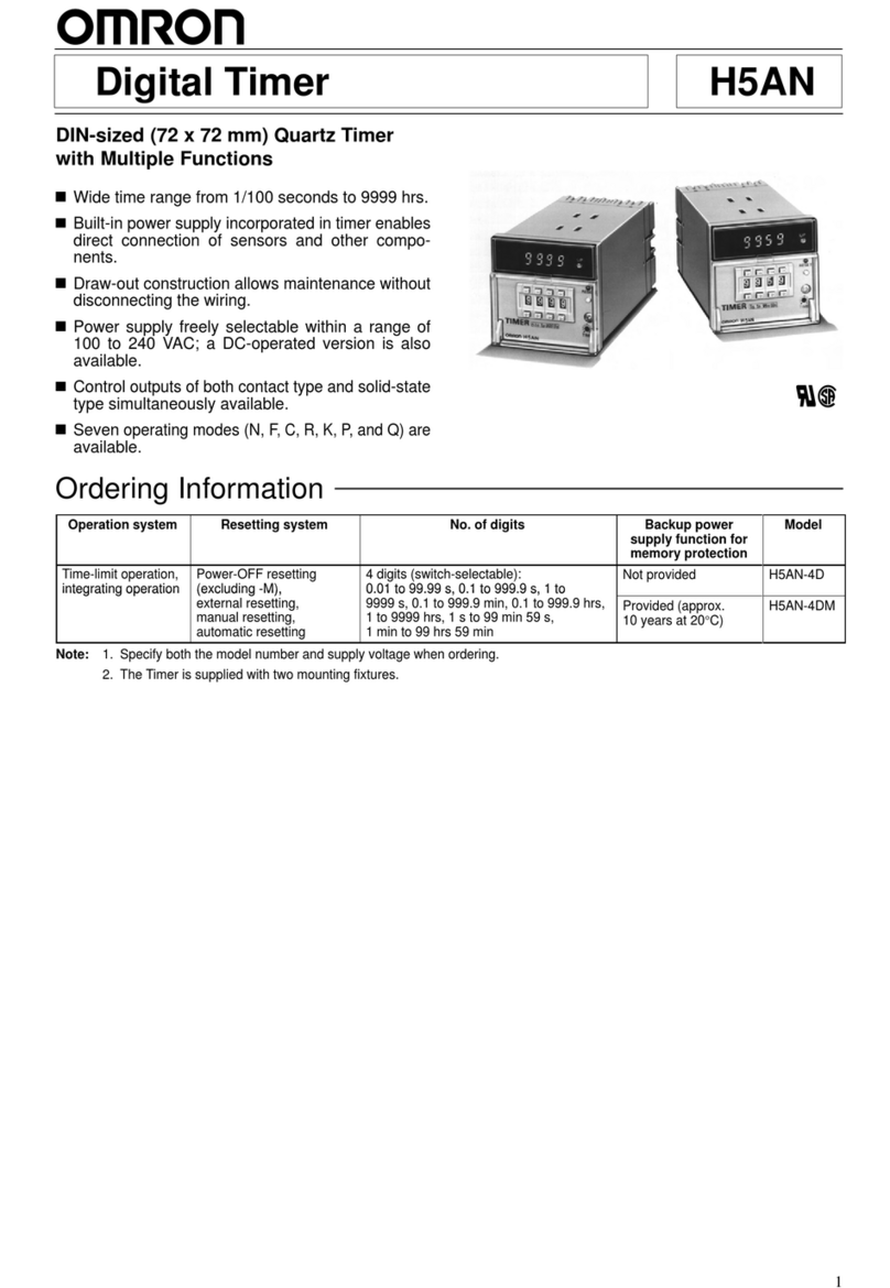
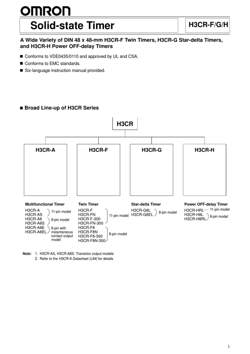
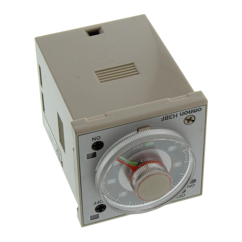
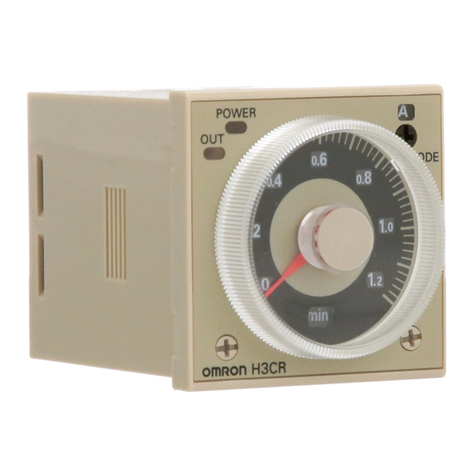
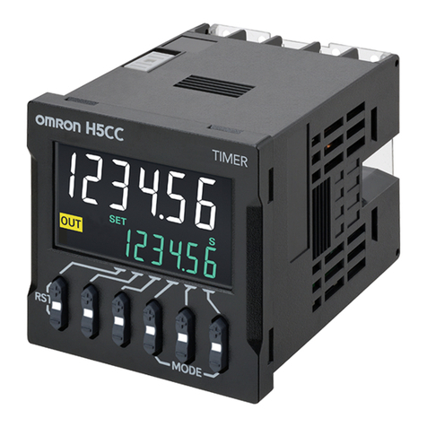
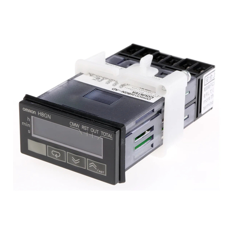
Omron H5CL User manual

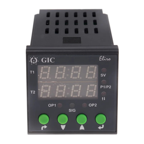
Digital Timer H5CL
1/16 DIN LED Timer with NEMA 4
Protection for a Wide Variety of
Applications
HWithstands washdown and dusty
environments
HLarge, easy-to-read LED displays
HSimple setting with increment and
decrement keys
HNEMA 4 rating only when used in
conjunction with Y92S-29 rubber gasket,
supplied with each unit
HPerforms signal ON-delay and cumulative
timing
RC
Ordering Information
Part number Contact output H5CL-AD H5CL-A
Transistor output
(photocoupler)
H5CL-ADS H5CL-AS
Timing functions Signal ON-delay and cumulative
Terminal form Terminal strip 11-pin round
Supply voltage 12 to 24 VDC 100 to 240 VAC, 50/60 Hz
Model Number Legend
H5CL-A
2 3 1. Fixed
2. D: DC supply voltage
3. S: Transistor output
1
JACCESSORIES (ORDER SEPARATELY)
Item Description Part number
Protective covers Soft cover Y92A-48F1
Hard cover Y92A-48
Finger-safe (shock-prevention) terminal cover (DC models only) Y92A-48T
Track mounting/
f
r
o
n
t
c
o
n
n
e
c
t
i
n
g
11-pin P2CF-11
f
ront connecting
socket 11-pin, finger-safe type; conforms to VDE 0106/P100 P2CF-11-E
Back connecting
s
o
c
k
e
t
f
o
r
p
a
n
e
l
11-pin P3GA-11
socket for panel
mounting (See note.) 11-pin, finger-safe type; conforms to VDE 0106/P100 P3GA-11 (with Y92A-48G)
m
o
u
n
t
i
n
g
(
S
e
e
n
o
t
e
.
)
Finger-safe terminal cover for P3GA-11 socket Y92A-48G
Mounting track 50 cm (1.64 ft.) x 7.3 mm (0.29 in.) PFP-50N
g
1 m (3.28 ft.) x 7.3 mm (0.29 in.) PFP-100N
1 m (3.28 ft.) x 16 mm (0.63 in.) PFP100N2
End plate PFP-M
Spacer PFP-S
Replacement parts Rubber gasket (supplied with each unit) Y92F-29
p
p
Panel mounting adapter (supplied with each unit) Y92F-30
Note: Y92A-48G is a finger-safe terminal cover for the P3GA-11 socket.

H5CLH5CL
2
Specifications
Item H5CL-Aj(AC models) H5CL-ADj(DC models)
Mounting DIN track, surface, and panel mounting (common) Panel mounting
External connections Socket Screw terminals
Enclosure ratings Panel surface: IEC IP66 and NEMA Type 4 (indoors) when Y92S-29 rubber gasket is used.
Digits 4 digits (zero suppress method)
Max. time settings 9.999 s (0.001-s unit), 99.99 s (0.01-s unit), 999.9 s (0.1-s unit), 9999 s (1-s unit),
99 min 59 s (1-s unit), 999.9 min (0.1-min unit), 99 h 59 min (1-min unit), 999.9 h (0.1-h unit)
Display modes Up (increment) and Down (decrement) selectable
Input signals Start, gate, reset, and key protection
Input method No-voltage input: via NPN transistor or switching of contact
Operating modes A (signal ON-delay), F (cumulative operation) selectable
Reset Power reset (A (signal ON-delay) mode only), external, manual resets
Sensor waiting time 216 ms typ., 250 ms max. (Control output is turned OFF and no input is accepted during sensor waiting
time.)
External power supply 50 mA at 12 VDC (±10%) ---
Display 7-segment LEDs (12 mm high, red LEDs for the present value, and 8 mm high, green LEDs for the set value)
Memory backup EEP-ROM (overwritten 200,000 times min.), can store data for 20 years min.
Mounting DIN track mounting, surface mounting, and panel
mounting
Panel mounting
Approvals UL 508, CSA C22.2 No.14; conforms to EN61010-1
JRATINGS
Item H5CL-Aj(AC models) H5CL-ADj(DC models)
Supply voltage 100 to 240 VAC, 50/60 Hz 12 to 24 VDC (permissible ripple: 20%
(p-p) max.)
Operating voltage range 85 to 264 VAC, 50/60 Hz 10.8 to 26.4 VDC
Power consumption Approx. 10 VA Approx. 3 W
Start, reset, gate inputs Min. pulse width: 1 ms/20 ms (selectable, same for all three inputs)
Key protection input Response time: 1 s max.
Power reset Min. power opening time: 0.5 s, excluding F (cumulative operation) mode
Control output Contact output SPDT, 3 A at 250 VAC, resistive load (cosφ=1); min. applicable load: 10 mA at 5/24 VDC
(P level, for reference value);
Transistor
output
NPN open collector, 100 mA max. at 30 VDC max., residual voltage 1.5 VDC max.

H5CL H5CL
3
JCHARACTERISTICS
Item H5CL-Aj(AC models) H5CL-ADj(DC models)
Repeat accuracy Power start: ±0.01% ±0.05 s max. (See Note 1.)
Signal start: ±0.005% ±0.03 s max. (See Note 1.)
Signal start, at transistor output model: ±0.005% ±3 ms max. (See Note 1 and 2.)
If the set value is within the sensor waiting time (250 ms max.) in the case of power start, the
control output of the H5CL will not be turned ON until the sensor waiting time passes.
Insulation resistance 100 MΩmin. (at 500 VDC) (between current-carrying terminal and exposed
non-current-carrying metal parts, and between non-continuous contacts)
Dielectric strength 2,000 VAC, 50/60 Hz for 1 min (between
current-carrying terminal and exposed
non-current-carrying metal parts)
1,000 VAC, 50/60 Hz for 1 min (between
non-continuous contacts)
1,000 VAC, 50/60 Hz for 1 min (between
current-carrying terminal and exposed
non-current-carrying metal parts, and
between non-continuous contacts)
Impulse withstand voltage 3.0 kV (between power terminals)
4.5 kV (between current-carrying terminal and
exposed non-current-carrying metal parts)
1.0 kV (between power terminals)
1.5 kV (between current-carrying terminal and
exposed non-current-carrying metal parts)
Noise immunity ±1.5 kV (between power terminals)
±600 V (between input terminals),
square-wave noise by noise simulator (pulse
width: 100 ns/1 µs, 1-ns rise)
±480 kV (between power terminals)
±600 V (between input terminals),
square-wave noise by noise simulator (pulse
width: 100 ns/1 µs, 1-ns rise)
Static immunity Destruction: 15 kV
Malfunction: 8 kV
Vibration resistance Destruction: 10 to 55 Hz, 0.75-mm single amplitude each in three directions
Malfunction: 10 to 55 Hz, 0.5-mm single amplitude each in three directions
Shock resistance Destruction: 294 m/s2(30G) each in three directions
Malfunction: 98 m/s2(10G) each in three directions
Ambient temperature Operating: --10 to 55°C (14 to 131°F) with no icing; if timers are mounted side-by-side: --10 to
50°C (14 to 122°F) with no icing
Storage: --25 to 65°C (--13 to 149°F) with no icing
Ambient humidity Operating: 35% to 85%
Service life Mechanical: 10,000,000 operations min.
Electrical: 100,000 operations min. (3 A at 250 VAC, resistive load)
EMC (EMI): EN50081-2
Emission Enclosure: EN55011 Group 1 class A
Emission AC Mains: EN55011 Group 1 class A
(EMS): EN50082-2
Immunity ESD: EN61000-4-2: 4 kV contact discharge (level 2)
8 kV air discharge (level 3)
Immunity RF-interference: ENV50140: 10 V/m (80 MHz to 1 GHz) (level 3)
Immunity Conducted Disturbance: ENV50141: 10 V (0.15 to 80 MHz) (level 3)
Immunity Burst: EN61000-4-4: 2 kV power-line (level 3)
2 kV I/O signal-line (level 4)
Materials Case: plastic (Munsell 5Y7/1), light gray
Weight Approx. 130 g Approx. 110 g
Note: 1. The values are based on the set value.
2. The value is applied for a minimum pulse width of 1 ms.
H5CLH5CL
4
Nomenclature
Indicator
1. Present Value
Red LEDs with a character height of 12 mm
Note: The decimal point will flash on the present value dur-
ing the timing operation in the following ranges:
0.1 to 999.9 min, 0 h 01 min to 99 h 59 min, and
0.1 to 999.9 h.
2. Preset Value
Green LEDs with a character height of 8 mm
3. Reset Indicator (orange)
4. Key Protection Indicator (orange)
5. Time Unit Display (orange)
6. Control Output Indicator (orange)
Operation Key
7. Reset (RST) Key
The RST Key initializes the present value and control output.
8. Increment Keys (1 to 4)
Up Keys 1 to 4 increment the preset value.
9. Decrement Keys (1 to 4)
Down Keys 1 to 4 decrement the preset value.
1
2
5
8
4
6
3
7
9
Stick the enclosed label here.
Operation
JDIP SWITCH SETTING
Pin no. Item OFF ON
1, 2, 3 Time ranges See table below.
4Display modes Up (Increment) Down (Decrement)
5Min. pulse width of inputs 20 ms 1ms
6Operating modes A (signal ON-delay) F (cumulative operation)
•Switches 1 to 6 are all set to OFF before shipping.
•The same switch settings apply to AC and DC models.
•Set the DIP switch before installation and operation of the unit.
•DIP switch setting changes made while the power is ON cannot take effect.
Time Ranges
1 2 3 Time range
ON ON ON 0.001 to 9.999 s
OFF OFF OFF 0.01 to 99.99 s
ON OFF OFF 0.1 to 999.9 s
OFF ON OFF 1 to 9999 s
ON ON OFF 0min01sto99min59s
OFF OFF ON 0.1 to 999.9 min
ON OFF ON 0h01minto99h59min
OFF ON ON 0.1 to 999.9 h
Timer Control with Power Start
When using the H5CL with power start, short-circuit the start input and input 0-V terminals.

H5CL H5CL
5
JOPERATING MODES
A Mode
Signal ON-delay
F Mode
Cumulative Operation
Power
Start
Gate
Reset
Control output
Set value
0
0
Set value
Display
mode
Power
Start
Gate
Reset
Control output
Set value
0
0
Set value
Display
mode
UP
DOWN
UP
DOWN
Dimensions
JH5CL-AV
VV
V
DIN Track/Surface/Panel Mounting (AC Versions)
JH5CL-ADV
VV
V
Panel Mounting (DC Versions)
6
6
44.8 x 44.8
(1.76 x 1.76)
48
(1.89)
48
(1.89)
48
(1.89)
48
(1.89)
14.4
72.5 (2.85)
64 (2.52)
70 (2.75)
44.8 x 44.8
(1.76 x 1.76)
Unit: mm (inch)

H5CLH5CL
6
Y92F-30 panel
mounting adapter
(provided)
Y92F-30 panel
mounting adapter
(provided)
48 (1.89) 62.5 (2.46)
98.7 (3.89)
48 (1.89)
JH5CL-AV
VV
V
With Panel Mounting Adapter
JH5CL-ADV
VV
V
With Panel Mounting Adapter
Panel Cutouts
Panel cutouts are as
shown below. (according
to DIN43700).
+1
-- 0
A = (48n--2.5)
Note: 1. The mounting panel thickness should be 1 to 4 mm.
2. It is possible to mount timers side by side, but only in one direction.
3. When the Timers are mounted closely side by side, the Timers will not be water-resistant.
7.5
48
7.5
Y92S-29 rubber
gasket (provided)
Panel
P3GA-11 back
connecting socket
(sold separately)
Y92S-29 rubber
gasket (provided)
Panel 60 min.
60 min.
A
n side-by-side mounting
45 +0.6
-- 0
45 +0.6
-- 0
44.8 x 44.8
(1.76 x 1.76)
58
(2.28)
58
(2.28)
51
(2.01)
51
(2.01)
H5CL-Aj
jj
jTimer with Front-Connecting P2CF-11 (-E) Socket
DIN Track Mounting
Note: See P2CF--11 Socket in Accessories (order separately).
120
(4.72)
H5CL-Aj
Timer
P2CF-11 (-E) Socket

H5CL H5CL
7
JACCESSORIES (ORDER SEPARATELY)
70
(2.76)
max.
P2CF-11 Track Mounting/Front-Connecting Socket
Terminal Arrangement/
Internal Connections
(Top View)
Surface Mounting Holes
Two, 4.5 dia. mounting holes
40±0.2
Two, 4.5
dia. holes
Eleven,
M3.5 x 7.5 sems
50 (1.97)
max.
31.2
(1.23)
max.
35.4
(1.39)
4
P2CF-11-E (Finger-Safe Terminal Type)
Conforming to VDE0106/P100
Two, 4.5 dia.
holes
Eleven,
M3.5 x 7.5 sems
7.8
(0.31)
70
(2.76)
max.
4
40±0.2
50
(1.97)
max.
35.4
(1.39)
31.2
(1.23)
max.
30
5
(0.20) 4.5
(0.18)
3
1.2
7.8
(0.31)
3
(0.12) 45
(0.18)
25.6
(1.01)
27
(1.06)
dia.
P3GA-11
Back-Connecting Socket Terminal Arrangement/
Internal Connections
(Bottom View)
45
(1.77)
4.5
16.3
6.2
45
(1.77)

H5CLH5CL
8
Finger-Safe Terminal Covers
Conforming to VDE0106/P100
Y92A-48G
Attachment for P3GA-11 Socket
Y92A-48T
Attachment for H5CL DC Models
Hard Cover
Y92A-48
Soft Cover
Y92A-48F1
Twelve, 6.4 dia. holes
34
(1.34) 47.7 x
47.7
48 x 48
(1.89 x 1.89)
47.4
(1.87)
16.5 24.6 27.6
(1.09)
JMOUNTING TRACK
PFP-100N/PFP-50N PFP-100N2
4.5
15 25 25 25 25 *
10 10
7.3+0.15
35+0.3 27+0.15
1
4.5
15 25 25 25 25 15
10 10
L
35+0.3 27 24
16
29.2
11.5
1,000 (500)
(see note)
Note: The values shown in parentheses are for the PFP-50N.
15 (5)
(see note)

H5CL H5CL
9
Installation
JTERMINAL ARRANGEMENT
AC Models
DC Models
Note: 1 and 6 are connected to each other internally.
8109
7
54
3
2 54
3
Gate Key protection
0V
Reset Start
12 to 24 VDC
Contact outputTransistor output
67
8
9
10
5
4
3
2
Reset
Start
Gate
Key protection
External power supply
12 VDC (50 mA max.)
11
1
8
9
11
Transistor outputContact output
100 to 240 VAC
Input common (0 V)
6
1
-- +
Load
(Sensor)
(--) (+)
Note: Power supply circuit is insulated from the internal circuit (or I/
O

H5CLH5CL
10
JINPUT CIRCUITS
Start, Reset, and Gate Input
H5CL-Aj(AC Models)
Key Protection Input
IN
Vin -- 3 . 5 V
(16V max.)
1kΩ
Internal circuit
Vin: Supply voltage
H5CL-ADj(DC Models)
IN
+12 V
1kΩ
Internal circuit IN Internal circuit
+5 V
4.7 kΩ
Note: No key input is effective while
key protection input is ON.
JINPUT CONNECTIONS
Open Collector Output Voltage Output
12 VDC
17653
--
7986
PLC or
sensor
0 V Output 12 VDC
PLC or
sensor
0 V Output
AC models
DC models
17653
--
7986
AC models
DC models
Gate input
Start input
Reset input
1
2 VDC output
Gate input
Start input
Reset input
12 VDC output
0V
0V
Contact input
7653
7986
AC models
DC models
Gate input
Start input
Reset input
Start, Reset, and Gate Input Specification
ON impedance: 500 Ωmax. (the leakage current is 5 to 20 mA when the impedance is 0 Ω.)
ON residual voltage: 2 V max.
OFF impedance: 100 kΩmin.
Maximum applicable voltage: 30 VDC max.
Two-Wire Sensor
7653
7986
Sensor
0V
AC models
DC models
Gate input
Start input
Reset input
0V
Applicable Two-Wire Sensor
Leakage current: 1.5 mA max.
Switching capacity: 5 mA min.
Residual voltage: 3 V max.
Operating voltage: 10 VDC
Note: When connecting a two-wire sensor to a DC models,
supply 24 VDC (21.6 to 26.4 VDC) to the timer.
Key Protection Input
43
106
AC models
DC models
Open collector
or
contact
0V
Key protection
input
Key Protection Input
ON impedance: 1 kΩmax.
(the leakage current is approx. 1 mA when the
impedance is 0 Ω.)
ON residual voltage: 0.5 V max.
OFF impedance: 100 kΩmin.
Maximum applicable voltage: 30 VDC max.
Note: The used contact should switch 1 mA at 5 V.

H5CL H5CL
11
Precautions
JPOWER SUPPLIES
Power
supply
Input Impossible
Unstable
Possible ImpossibleUnstable
160 ms 0to90ms
DC: 5 ms
AC: 10 ms
0to500ms
ON
OFF
When turning the power ON and OFF, input signal reception
is possible, unstable, or impossible (as shown here).
Apply the power supply voltage through a relay or switch so that
that the voltage reaches a fixed value immediately.
Turn the power ON and OFF with relay with a rated capacity of
10 A minimum to prevent contact deterioration due to inrush
current caused by turning the power ON and OFF.
JTIMER CONTROL WITH POWER START
The timer will function 160 to 250 ms after the power is turned
ON (refer to the above diagram). The control output will be
delayed for any set value less than 250 ms.
When the H5CL is used with power start in F mode (i.e.,
cumulative operation with output on hold), there will be a timer
error (approximately 100 ms each time the H5CL is turned on)
due to the characteristics of the internal circuitry. Use the H5CL
with signal start if timer accuracy is required.
JTRANSISTOR OUTPUT
The transistor output of the H5CL is insulated from the internal
circuitry by a photocoupler, so the transistor output can be used
as both NPN and PNP output.
Load
Timer
Power for load
Inductive load
Timer
Power for load
The diode connected to the collector of the output transistor
is used to absorb inverted voltage that is generated when an
inductive load is connected to the H5CL.
JSELF-DIAGNOSTIC FUNCTION
The following displays will appear if an error occurs.
Display Error Output
status
Correction Set value
after
correction
e1 CPU OFF Press
RST Key
or turn
power off
and then
ON
No
change
e2 Memory
(See Note.)
0
Note: This includes times when the life of the EEPROM has
expired.
JOPERATING ENVIRONMENT
When using the Timer in an area with excess electrical noise,
separate the Timer, wiring, and the equipment which generates
the input signals as far as possible from the noise sources. We
recommend shielding the input signal wiring to prevent electrical
interference. Organic solvents (such as paint thinner), as well as
very acidic or basic solutions can damage the outer casing of the
Timer.
JCHANGING THE PRESET VALUE
When changing the preset value during a timing operation, output
will turn ON if the preset value is changed as follows (since the
constant read-in system is in use):
Display mode UP: Present value ≥preset value
Display mode DOWN: Elapse time ≥preset value
(Present value = 0)
Note: When in down mode, the changed amount of preset value
is added to or subtracted from the present value.
Reset with a Preset Value of 0
The output will go ON when the start signal is input. The output
will be OFF while the reset key is pressed or the reset input
is ON.
JMEMORY BACKUP
All data is stored in the EEPROM when there is power failure.
The EEPROM can be overwritten more than 200,000 times.
Operating
mode
Overwriting timing
A mode When the H5CL is turned off after changing
the set value.
F mode When the H5CL is turned off after changing
the set value, turning the start input, or the
reset input ON.
JPANEL MOUNTING
The H5CL’s panel surface is water-resistant, conforming to
NEMA 4 (indoors) and IP66. In order to prevent the internal
circuit from water penetration through the space between the
timer and operating panel, attach a rubber packing (provided with
the H5CL) between the timer and operating panel and secure the
rubber gasket with the Y92F-30 panel-mounting adapter.
The space between the screw head and the
adapter should be 0.5 to 1 mm.
0.5to1mm
JAVOID DAMAGE WHEN TESTING
When performing a dielectric strength test (or similar test) on the
H5CL mounted to a control panel, disconnect the H5CL from the
connecting circuit, or short-circuit all the terminals of the H5CL to
avoid damaging the H5CL.
JINTERNAL CONNECTIONS FOR DC
MODEL
Terminal 1 (power supply terminal) and terminal 6 (input
common: 0 V for input) of DC model H5CL are internally
connected to each other.
JDIP SWITCH SELECTION
DIP switch setting while the H5CL is turned on will not be valid
until the H5CL is turned off and on.

H5CLH5CL
12
Cat.No. GCTMCN13/02 Specifications subjecttochange without notice. Printed in U.S.A.
OMRON ELECTRONICS LLC
OneEastCommerceDrive
Schaumburg, IL 60173
NOTE: DIMENSIONS SHOWN ARE IN MILLIMETERS. To convert millimeters to inches divide by 25.4.
1-800-55-OMRON
OMRON CANADA, INC.
885 Milner Avenue
Scarborough, Ontario M1B 5V8
416-286-6465
R
OMRON ON--LINE
Global -- http://www.omron.com
USA -- http://www.omron.com/oei
Canada -- http://www.omron.com/oci
Other manuals for H5CL
1
This manual suits for next models
4
Table of contents
Other Omron Timer manuals