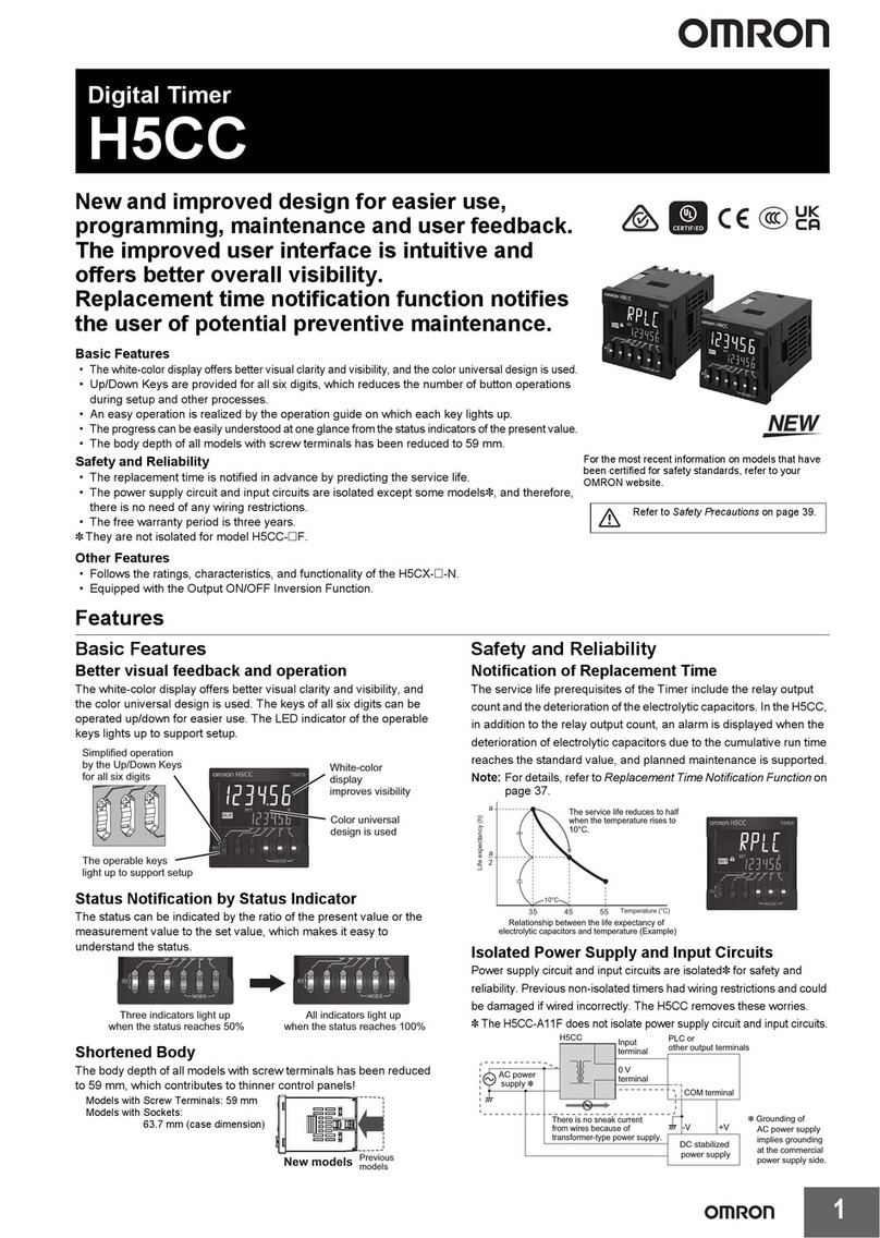
Omron H5F - User manual

INSTRUCTION MANUAL
MODEL
H5F
DIGITALDAILYTIMESWITCH
■Safety
Precautions
‥‥‥ P1
■Table of Contents
‥‥‥ P5
■Operation
‥‥‥ P7
■Installation
‥‥‥P29
© All Rights Reserved.
Thank you for purchasing this OMRON product. This INSTRUCTION
MANUAL describes the information such as function, performance, and
how to use the product required for using the product.
• Please operate the product by the qualified specialist having the
electrical know how.
• Read this instruction manual with enough, and use the product with
enough understanding.
• Keep this instruction manual close at hand and use it for reference
during operation.
1617398-8D
OMRON Corporation
English
H5F
TIME SWITCH
5
00
3
00
PW
ON
PM
PM
15A
10A
RES.
43
2
1
250VAC
24VDC
100to240VAC
50/60Hz
2.4VAmax.
H5F
TIME SWITCH
5
00
3
00
PW
ON
PM
PM
H5F
TIME SWITCH
5
00
3
00
PW
ON
PM
PM
RES.
4
3
2
12.4VAmax.

Safety Precautions
-1-
●
Graphic symbol
●
●
●Prohibitionagainstdisassembly
Notificationofdisassemblyofproducts,when
doingsocancausepossibleelectricshocks.
Generalwarning
Notificationofgeneral,unspecifiedactions
thatusersmustperform.
Warningagainstrupture
Notificationofpossibleruptureundercertain
conditions.
●
●Warningagainstelectricshocks
Notificationofpossibleelectricshocksunder
certainconditions.
Generalwarning
Notificationofgeneral,unspecifiedprohibition
items.
●
Key to Warning Symbols
CAUTION
Indicates information that,if not followed,could
result in relatively serious or minor injury,
property damage,or faulty operation.

Never disassemble, deform, subject to heat over
100˚C or dispose in fire. The product has a buit-in
lithium battery. Fire, Explosion and Burn Hazard.
The life expectancy of the output relay varies considerably
according to its usage. Use the output relay within its rated
load and electrical life expectancy. If using the Time Switch
beyond its ratings is unavoidable, use it together with an
electromagnetic switch or contactor in the way described
on page 32. If the output relay is used beyond its life
expectancy, its ontacts may become fused or there may
be a risk of fire.
Before changing times or other settings while power
is being supplied, either turn OFF the power on the
load side or set the Out ON/OFF switch to OFF and
confirm the safety of the system.
Tighten the terminal screws securely. The
recommended tightening torque is 8.67 in.lb.
(0.98 N·m)[10.4 in.lb. max (1.17 N·m max)].
Loose screws may result in fire or malfunction.
Never disassemble, repair or modify the product.
This may cause electric shock, fire or malfunction.
Do not use the product where flammable or
combustion gases are present. There may be a risk
of explosion.
Do not touch any of the terminals while power is
being supplied. Doing so may result in electric shock.
Be sure to mount the terminal cover after wiring.
-2-
●
Precautionary Information
CAUTION

-3-
Please comply strictly with the following instructions which are intended
to ensure safe operation of the controller.
(1) Application of voltages other than the rated voltage may seriously
damage the internal elements.
(2) Separate the Time Switch from any potential sources of noise, such
as high-voltage lines. When using inductive loads
(e.g., electromagnetic relays), connect noise-absorbing elements
(resistor and capacitor) to both ends of the coil.
(3) Do not install the Time Switch close to sources of excessive static
electricity (e.g.,forming compounds, powders, or fluid materials being
transported by pipe).
(4) Locations subject to temperatures or humidity outside the range
specified in the specifications.
(5) Mounting the Time Switches side-by-side may reduce the life
expectancies of internal components.
(6) Do not use the Time Switch in environments subject to shocks or
vibration beyond the ranges specified in this document.
(7) Do not use the Time Switch in dusty environments, in locations where
corrosive gases are present, or in locations subject to direct sunlight.
(8) Store at the specified temperature. If the Time Switch has been stored
at a temperature of less than –10℃, allow the Time Switch to stand at
room temperature for at least 3 hours before use.
(9) This product is not waterproof or oil-proof. Do not use it in locations
where water or oil may enter the product interior.
(10) To prevent damage to the exterior of the Time Switch, it must not be
exposed to organic solvents (e.g. Paint thinner or benzine), strong
alkalies, or strong acids.
(11) When using heaters, be sure to use a thermal switch for the load circuit.
(12) Take adequate protective measures for the power supply of the Time
Switch (such as providing a breaker and fuse).
Precautions for Safe Use

-4-
(1) Be sure to wire the terminals correctly.
(2) Perform wiring using appropriate wires of the type specified in this
document. Using a different type of wire may result in burn injury or
fire due to abnormal heat generation.
(3) Do not use the Time Switch in the following locations:
• ELocations where condensation may occur due to high humidity levels
• ELocations subject to extreme temperature variations
(4) Do not leave the Time Switch for long periods (i.e., one month or
longer) at a high temperature with output current in the ON state.
Doing so may result in the premature deterioration of internal
components (e.g., electrolytic capacitors).
(5) Always maintain the power supply voltage within specifications.
(6) Apply the full power supply voltage through the breaker, switch, and
relay contacts simultaneously. Gradually increasing the voltage may
result in malfunction.
(7) When the power is turned ON, an inrush current will flow for a short
time (approx. 2 A for 0.3 ms at 264 VAC). Depending on the power
supply capacity, operation may not start. Be sure to use a power supply
with a sufficient capacity and a breaker.
(8) None of the Time Switch components are user-replaceable, including
the battery.
Precautions for Correct Use
Suitability for Use
OMRON shall not be responsible for conformity with any standards, codes, or
regulations that apply to the combination of the products in the customer's
application or use of the product.
Take all necessary steps to determine the suitability of the product for the
systems, machines, and equipment with which it will be used.
Know and observe all prohibitions of use applicable to this product.
NEVER USE THE PRODUCTS FOR AN APPLICATION INVOLVING SERIOUS
RISK TO LIFE OR PROPERTY WITHOUT ENSURING THAT THE SYSTEM
AS A WHOLE HAS BEEN DESIGNED TO ADDRESS THE RISKS, AND THAT
THE OMRON PRODUCT IS PROPERLY RATED AND INSTALLED FOR THE
INTENDED USE WITHINTHE OVERALL EQUIPMENT OR SYSTEM.
See also Product catalog forWarranty and Limitation of Liability.
Operation
Safety precoutions ・・・・・・・・・・・・・・・・・・・・・・・・・ 1
Precautionary information ・・・・・・・・・・・・・・・・・・・ 2
Precautions for safe use・・・・・・・・・・・・・・・・・・・・ 3
Suitability for use ・・・・・・・・・・・・・・・・・・・・・・・・・・・4
Table of contents ・・・・・・・・・・・・・・・・・・・・・・・・・ 5.6
1. Nomenclature・・・・・・・・・・・・・・・・・・・・・・・・・・
2. Operating functions・・・・・・・・・・・・・・・・・・・・・
3. Selecting the mode ・・・・・・・・・・・・・・・・・・・・・
4. Setting the time・・・・・・・・・・・・・・・・・・・・・・・・
5. Setting timer operation ・・・・・・・・・・・・・・・
6. Setting pulse-output operation ・・・・・・・・
7.
Setting partial operation on specified day
・・
8. Changing (Confirming) settings ・・・・・・・
9. Clearing the settings・・・・・・・・・・・・・・・・・
10. Setting (Temporary) Holidays ・・・・・・・・・・・
11. Summer time(DST) ・・・・・・・・・・・・・・・・・・・・
12. Switching between 12-hour(am/pm) and
24-hour Display ・・・・・・・・・・・・・・・・・・・・・・・
7
8
9
10
11.12
13.14
15.16
17.18
19.20
21
22
22
-5-
Table of Contents

Installation
-6-
13.
Override and automatic return operation
・・
14. Program check function・・・・・・・・・・・・・・・・・・
15. Operation while the power supply is OFF ・・
16. Setting precautions・・・・・・・・・・・・・・・・・・・・・
17. Setting examples ・・・・・・・・・・・・・・・・・・・・・・
18. Troubleshooting ・・・・・・・・・・・・・・・・・・・・・・・
23.24
25
26
26
27
28
1. Dimensions and mounting dimensions・・
2. Connections・・・・・・・・・・・・・・・・・・・・・・・・・・・
3. Wiring ・・・・・・・・・・・・・・・・・・・・・・・・・・・・・
4. Output (built-in relay) life expectancy・・・・・・
5. Ratings and performance characteristics ・・
6. EN/IEC standards ・・・・・・・・・・・・・・・・・・・・・・
7.Recordofsettings ・・・・・・・・・・・・・・・・・・・・・・
23.24
31
31.32
33
33
34
34

<Front Panel>
<Display>
Operation
-7-
38
d88 s
m
PM
AM
88
P
S
P
AM
+1h
PM
88
●
●
SU MO TU WE TH FR SA
h KEY
•
Used to set the hours.
•
Used to switch between 12-hour
(am/pm) and 24-hour display.
MODE KEY
• Used to switch between run mode, time
adjustment mode, and the operation
d/TEST KEY
•
Used to select the day.

•
Used to enter/leave
program check.
TMR/ PKEY
• Used to select timer operation or pulse-
output operation.
CLR/+1h KEY
• Used to clear the settings.
• Used to set/clear summer time.
SELECT/HOLIDAY
KEY
• Used to set/clear specified days.
• Used to enter/leave holiday setting
mode.
m/ PWD KEY
• Used to set the minutes.
• Used to set the pulse time width.
WRITE KEY
• Used to make the settings.
• Used to confirm the settings in
program check.
OUT「ON」「OFF」
SWITCH
ON: Output ON regardless of the settings.
AUTO: Automatic operation determined
by the settings.
OFF: Output OFF regardless of the
settings.
※:
Overrideandautomaticreturn
operation can be executed by
using this key in combination
with the Write Key.
1.Nomenclature
ON
PW
SU MO TU WE TH FR SA
OUT
OUT
ON
AUTO
OFF
POWER
TMR/P
CLR
+1h HOLYDAY TEST
SELECT d WRITE
m/PWDMODE h
Pulth Width Unit Indicator
Partial operation on
specified day Indicator
Current Day Indicator
Summer Time Indicator
• Lit when the Time Switch is set to
summer time.
Operation Setting
Mode Indicator
Next Operation Indicator
• Run mode: Displays the time of the next control-output operation.
• Operation setting mode: Displays the program number of the setting.
• Holiday setting: Displays a symbol indicating that holiday setting is in progress.
• Program check: Displays a symbol indicating that the Time Switch is in program check.
Pulse-output operation Indicator
• Lit during pulse-output operation.
• Not lit during timer operation.
Power Indicator
• Lit when power is supplied
to the Time Switch.
Time adjustment mode
indicator
Output indicator
• Turns ON when control output
turns ON.
Display of current time /
operation time,time width
Operation Day Indicator
• Lit: Operation Day
• Not Lit: Non-Operation Day
• Flashing: specified Operation Day

-8-
P.23
Using the Out ON/OFF switch and the Write Key,
regardless of the settings, control output is held in the
ON state until the next OFF time.
• Operation after the output turns OFF (or ON) will be
determined by the settings.
•
This function can be used with pulse-output operation.
Override and automatic
return operation
P.15
The Time Switch operates according to only some of the
settings on a user-specified day.
Example (Sunday selected as specified day):
Monday to Saturday: 8:00 to 12:00 (No. 1)
13:00 to 17:00 (No. 2)
Sunday: 8:00 to 12:00 (No. 1)
•
The Time Switch cannot be set to operate only on a specified day.
•
This function can be used with pulse-output operation.
Partial operation on specified day
P.13
P.21
It is possible to set a day in the current week on which
the Time Switch will not operate.When that day has
passed, operation will continue according to the regular
settings, and the Time Switch will operate as normal on
that day from the following week.
・This function can be used with pulse-output operation.
Holiday
−
Control output is continuously held in the ON
state, regardless of the settings, using the Out
ON/OFF switch.
Forced ON/OFF
Operation
Output turns ON for a fixed period (pulse) at the set
time.
• Pulse Width :1 to 59s,1 to 60 min
• One pulse-output operation set counts as one step.
• Up to 24 steps can be set.
Pulse-Output Operation
P.11
Output control is determined by the ON/OFF time
settings.
• Minimum setting interval: 1 min
• One ON/OFF set counts as two steps.
• Up to 24 steps can be set.
Timer Operation
(ON / OFF)
Remarks
Explanation
Operating function
2. Operating Functions
ON time
ON time
Settings
Settings
Settings
Operation
day
Current
week
Following
week
Operation
day Holiday
Specified
day
Program 1
(Specified) Program 2
Output
Operation Start
OFF time
Pulse Width

All of the modes can be selected using , , and Keys.
Move to the desired mode using the method shown below.
Operation Date
Setting Mode
Operation Time
Setting Mode
Time Adjustment
Mode
Run Mode
MODE
MODE
MODE
MODE
(2 s min.)
• Set the present day and time.
(Refer to page 10.)
• Control output operates
according to the settings.
• Set, confirm, change, or clear
the operation time setting. Also,
set the pulse width for pulse
operation. (Refer to page 11.)
• Set, confirm, change, or clear the
operation day and specified day
settings. (Refer to page 11.)
MODE HOLIDAY
-9-
Program check
function
『test』
(2 s min.)
(1 s min.)
TEST
Note 1
TEST
TEST
• The days and times when
output will actually turn ON/OFF
are displayed chronologically.
(Refer to page 25.)
Note 1: After the last item is displayed, the mode automatically returns to run mode.
Note 2: At the time of purchase, the mode is the run mode.
• Set a special day when the
Time Switch will not operate
temporarily. (Refer to page 21.)
Holiday Setting
Mode
『hday』
Note 2
3. Selecting the Mode
HOLIDAY HOLIDAY

-10 -
≪Note ≫
・The set time is enabled when the key is pressed.
・The time can be displayed in either 12-hour (am/pm) or 24-hour display.
【Example】Changing the current time setting from Wednesday
10:30 am to Monday 4:00 am.
①
Press the for 1 s min. to enter time
adjustment mode. The symbol flashes.
② Move the ▼symbol to Monday using
the Key. Change the time to 4:00 am
using the and Keys.
m/ PWD
④ Press the Key 3 times to return to
the run mode.
h
③Press the Key. The colon will
flash and the clock will start (from 0 s).
WRITE
The color indicates flashing
≪factorysetting≫
At the time of delivery,the mode is run mode and
there is no current time setting.before making any
other settings,press the Key for 1 s min, to
enter time adjustment mode and set the current time
using the above procedure.
<Display of factory setting >
4. Setting the Time
WRITE
d
MODE
MODE
MODE
10 30
AM
SU MO TU WE TH FR SA
ON
PW
400
400
AM
ON
PW
400
AM
ON
PW
AM
AM
308
-- --
----
●
●
PW
●
●

【Example】Setting the Time Switch to operate from Monday to
Friday between 8:30 am and 5:15 pm
①
Enter operation time setting mode using the
Key. The symbol flashes.
②
Set the ON time to 8:30 am using the and
Keys.
③
Press the Key.
(If only the hour or the minute (but not both)
is set, the operation setting time display will
flash to indicate an error.)
④Set the OFF time to 5:15 pm using the
and Keys.
SU MO TU WE TH FR SA
8:30 am 5:15 pm
-11 -
The color indicates flashing
Non-operation
Day
Non-operation
Day Operation
Day Operation
Day Operation
Day Operation
Day Operation
Day
5. Setting Timer Operation
MODE
h
h
m / PWD
m/ PWD
WRITE
-- --
1P
PW
830
1P
AM
PW
-- --
1P
PW
515
1P
PM
PW
SU MO TU WE TH FR SA

⑥
Press the Key to enter operation date
setting mode.
⑦
Move the ▼symbol to Saturday (or Sunday)
using the Key. Clear the operation day
indicator ( ) by pressing the Key.
≪Note≫
•
Up to 12 sets of ON-OFF settings are possible. Be sure to set both ON
and OFF times. If only the ON time is set, the setting will be iinvalid.
• At the time of delivery,all days are set as operation days.
• Continuous operation for more than 24 hours is possible by
combining 2 or more sets of settings. (Refer to pages 26 and 27.)
• pulse-output operation and timer operation cannot be used at the
same time. (Refer to page 13.)
⑧
Press the Key.
The Time Switch will enter run Mode and
operation based on the settings will start.
⑤
Press the Key.
(Repeat steps 2 to 5 to make other settings
if necessary.)
-12 -
The color indicates flashing
Lit (Operation Day)
Not LIt (Non-operation Day)
WRITE
WRITE
WRITE WRITE
MODE
MODE
d
-- --
2P
PW
P
PW
P
PW
10 30
155
PM
AM
●
●
ON
PW
SU MO TU WE TH FR SA

④ Press the Key.
Using pulse-output operation, the Time Switch can be set to operate
at the same time every day for a fixed period.
【Example】Setting the Time Switch to turn ON for 30 s from 8:25 am,
Monday to Friday.
②
Press the Key to set the Time Switch
for pulse-output operation. The symbol
flashes. (The Time Switch is set for timer
operation at the time of delivery.)
③
Set the pulse width to 30 s using the
Key. (The pulse width can be set in the range
1 to 59 s or 1 to 60 min.)
8:25 am
30s
-13 -
P
①
Enter operation time setting mode using the
Key. The symbol flashes.
The color indicates flashing
6.Settingpulse-outputoperation
MODE
WRITE
SU MO TU WE TH FR SA
Non-operation
Day
Non-operation
Day Operation
Day Operation
Day Operation
Day Operation
Day Operation
Day
TMR / P
m/ PWD
-- --
1P
PW
--
P
P
PW
30 s
P
P
PW
-- --
1P
P
PW
SU MO TU WE TH FR SA

⑤
Set the ON time (the time when pulse-output
operation starts) to 8:25 am using the and
Keys.
⑦
Press the key to enter the operation
date setting mode.
≪Note≫
・Up to 24 sets of settings are possible.
・Switching between timer operation and pulse-output operation will clear the
operation start time, operation day, and pulse width settings.
・pulse-output operation and timer operation cannot be used at the same time.
⑨Press the Key. The Time Switch will
enter run mode and operation based on the
settings will start.
⑥Press the Key.
(Repeat steps ⑤and ⑥
to make other settings if necessary.)
-14 -
The color indicates flashing
⑧
Move the▼symbol to Saturday (or Sunday)
using the Key. Clear the operation day
indicator ( ) by pressing the Key.
Lit (Operation Day)
Not LIt (Non-operation Day)
WRITE
WRITE
WRITE WRITE
MODE
MODE
h
d
m/ PWD
825
1P
P
AM
PW
-- --
2
P
P
PW
P
P
PW
P
P
PW
730
258
AM
P
AM
●
●
PW
SU MO TU WE TH FR SA

④
Set the OFF time for the specified day to
0:30 pm using the and Keys.
The Time Switch can be set to operate according to only some of the
settings on a user-specified day.
【
Example
】
Monday to Friday: ON at 8:30 am; OFF at 0:30 pm
ON at 1:15 pm; OFF at 5:15 pm
Saturday: ON at 8:30 am; OFF at 0:30 pm
②
Press the Key. The symbol will
be displayed. Set the ON time for the
specified day to 8:30 am using the and
Keys.
SELECT
③Press the Key.
S
●8:30 am to 0:30 pm (Specified Day Operation)
▲1:15 pm to 5:15 pm
● ▲ ● ▲ ● ▲ ● ▲ ● ▲ ●
-15 -
①
Enter operation time setting mode using the
Key.
The color indicates flashing
7.
Setting partial operation on specified day
MODE
h
h
WRITE
SU MO TU WE TH FR SA
Specifird
Day
Non-operation
Day Operation
Day Operation
Day Operation
Day Operation
Day Operation
Day
m / PWD
m / PWD
-- --
1P
PW
830
1P
S
AM
PW
-- --
1P
S
PW
030
1P
S
PM
PW
SU MO TU WE TH FR SA

⑦
⑧
Move the ▼symbol to Saturday using the
Key.Set the operation day indicator to specified
day by pressing the Key. And move the
▼symbol to Sunday using the Key.Clear the
operation day indicator by pressing the Key.
≪Note≫
・specified operation can be set for two or more programs. The specified day
must be specified, however, for each program using the Key.
・Two or more days can be specified as specified days.
・specified days can also be specified for pulse-output operation.
⑨
Press the Key.
The Time Switch will enter run mode and
operation based on the settings will start.
The operation day indicator ( ) of the
specified day will flash.
⑥
⑤
Press the Key.
Set the time to 1:15 pm using the and
Keys.
-16 -
The color indicates flashing
Lit(Operation day)
Not lit(Non-operation day)
Flashing(Specified day)
Press the Key.
Set the time to 5:15 pm using the and
Keys.
Press the Key.
Press the Key to enter operation date
setting mode.
MODE
MODE
SELECT
h
m / PWD
WRITE
h
m / PWD
WRITE
WRITE
WRITE
WRITE
WRITE
WRITE WRITE
d
d
115
2P
PM
PW
515
2
P
PM
PW
P
PW
P
PW
10 30
300
PM
AM
●
●
ON
PW
SU MO TU WE TH FR SA

Changing (confirming) timer operation settings
【Example1】Changing the ON time for program No.1 from
8:30 am to 7:45 am
② Change the ON time to 7:45 am using
the and Keys.
⑤
Press the Key.
The Time Switch will enter run mode and
operation will start.
③
Press the Key. The OFF time for program
No.1 will be displayed. (The changes will not be
enabled unless the Key is pressed. Make
changes, if necessary, using the same
procedure as for ON time.)
④
Press the Key to enter operation date
setting mode. The operation dates will be
displayed. (Make changes, if necessary,
using the and Keys.)
-17 -
①
Enter operation time setting mode using the
Key. The ON time for program No.1 will
be displayed.
≪Note≫
• Operation based on the changed settings will start as soon as the Time Switch returns to run mode.
The color indicates flashing
8. Changing (Confirming) Settings
MODE
WRITE
WRITE
WRITE
h
d
m / PWD
MODE
MODE
830
1P
AM
ON
PW
745
1P
AM
ON
PW
630
1P
PM
ON
PW
P
ON
PW
10 30
306
PM
AM
●
●
ON
PW
SU MO TU WE TH FR SA

Changing (confirming) pulse-output operation settings
【Example2】Changing the pulse width from 30 s to 20 s
② Change the pulse width to 20 s using
Key.
⑤
Press the Key.The Time Switch will
enter run mode and operation will start.
③
Press the Key. The ON time for
program No.1 will be displayed.
(The changes will not be enabled unless
Key is pressed. Make changes, if
necessary, using the and key.)
-18 -
④
Press the key to enter operation date
setting mode.The operation dates will be
displayed. (Make changes, if necessary,
using the and key.)
≪Note≫
• Operation based on the changed settings will start as soon as the
Time Switch returns to run mode.
The color indicates flashing
①Enter operation time setting mode using
key. The pulse width is displayed.
MODE
MODE
MODE
m / PWD
m / PWD
WRITE
WRITE
h
WRITE
d
30
s
P
P
PW
20
s
P
P
PW
740
1
P
P
AM
PW
P
P
PW
730
407
AM
P
AM
●
●
PW
SU MO TU WE TH FR SA

-19 -
Clearing the settings for individual programs
【Example 1】Clearing the settings for program No.2
②
Press the Key 2 times to display the
settings for program No.2.
≪Note≫
• Settings for pulse-output operation can be cleared for individual
programs in the same way.
③
Press the Key. (Both the ON and OFF
settings are cleared with just one operation.
Output is temporarily maintained by the
condition before setting is cleared.)
CLR
④
Press the Key twice.The Time Switch
will enter run mode and operation based on
the new settings will start.
The color indicates flashing
①
Enter operation time setting mode using
Key.The ON time for program No.1
will be displayed.
9. Clearing the Settings
MODE
MODE
WRITE
830
1P
S
AM
ON
PW
115
2P
PM
ON
PW
-- --
2P
10 30
300
PM
AM
●
●
ON
PW
ON
PW
SU MO TU WE TH FR SA
Other manuals for H5F -
2
Table of contents
Other Omron Timer manuals

Omron
Omron H7AN User manual

Omron
Omron H3DS Series User manual

Omron
Omron H3CR User manual

Omron
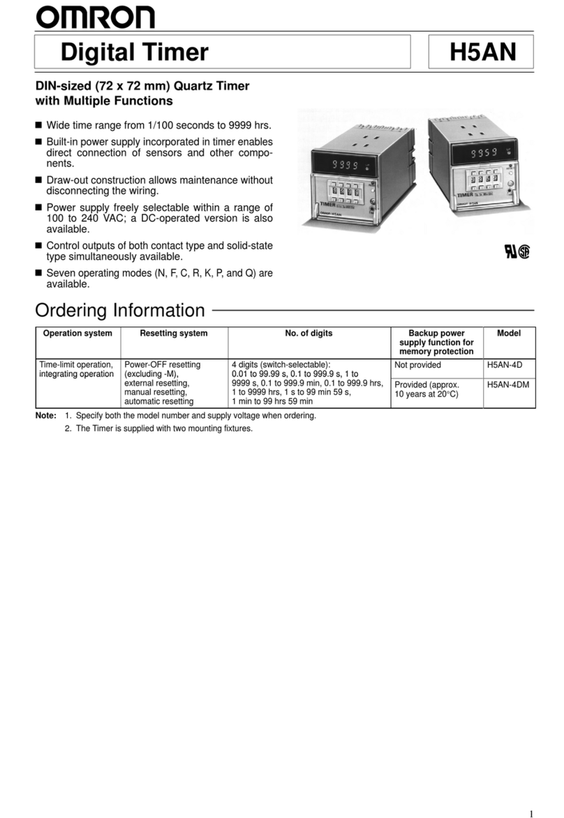
Omron H5AN Series User manual

Omron
Omron H5CR series User manual

Omron
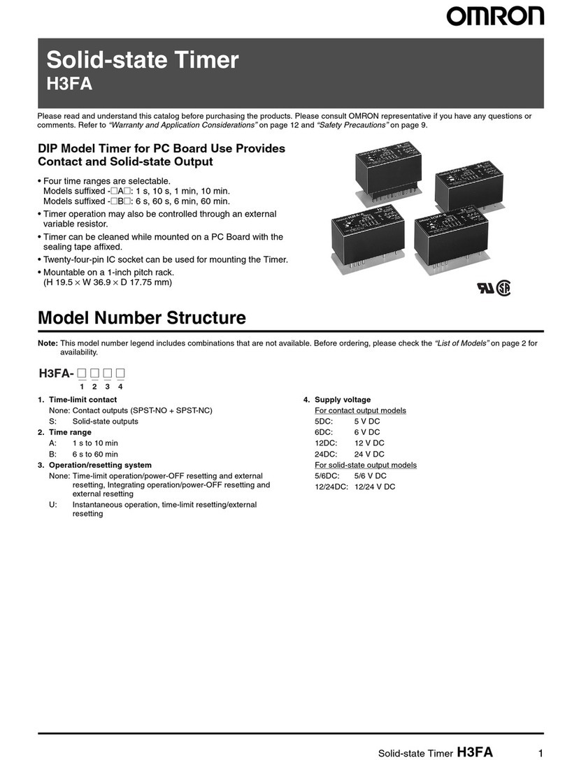
Omron H3FA - User manual

Omron
Omron H2A - User manual

Omron
Omron H3DE-F User manual

Omron
Omron H3CR -A User manual

Omron
Omron H3CR-A8 User manual