manuals.online logo
Brands
  1. Home
  2. •
  3. Brands
  4. •
  5. Optex
  6. •
  7. Security Sensor
  8. •
  9. Optex OVS-50TNR User manual

Optex OVS-50TNR User manual

OVS-50TNR Quick Setup Guide
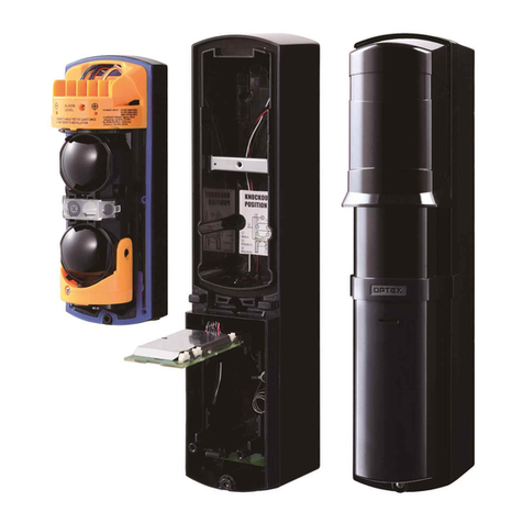
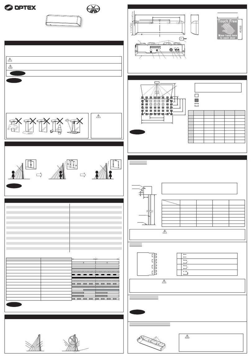
2. Remove the main optical unit from the transmitter and receiver.
OPTEX Inc.
(East Coast Office)
8510 McAlpine Park Dr.
Suite 108
Charlotte, NC 28211
18730 S. Wilmington Ave, Unit 100
Rancho Dominguez, CA 90220
Ph 800 877-6656
Fax 310 898-1098
www.optex-vs.com
1. Remove front covers, then cable connectors of transmitter and receiver.
2
Interface
board
1
Remove the bottom cover:
Loosen the cover
lock screw
Pull Pull and
slide up
Loosen the main unit
cover lock screw
Remove the main unit cover: Unplug the wired
connectors:
Take the main optical unit out
of the back housing
123
Mounting and Wiring (you must remove sensor from backplate for mounting)
continued on the back
3. Mount and wire the units
Mounting holes
(receiver and transmitter):
Knockout position
Mounting
hole
(knockout)
Mounting
hole
Using a screwdriver or similar tool, break the
knockout position in the back housing. Again using a screw-
driver or similar tool,
break the knockout
position in the back
housing.
(receiver only):
12
Use bottom knockouts for
external wiring
(knockout)
Knockout
Transmitter and receiver:
Remove the main optical unit from the back housing
Loosen the optical unit mounting screw.
Note: Optical unit shown at 90°
4. Align transmitter, then receiver:
Using the template, mount the back
housing to the wall or post.
Open the plate and then
route the Gate Operator
wires from the rear of the
back housing through the
knockout holes. Adjust
the wires so that they ex-
tend about 4 inches from
the holes. Use supplied
putty to ll holes with the
wires.
Look into the sniper viewnder and perform
alignment of the horizontal and vertical angles
using the alignment dial.
Checking the indicator LED and ne alignment.1 2
4
< How to look into the viewfinder >
Note>>
Left eye
Right eye
From right side
From left side
<
Vertical alignment
>
Turn the vertical alignment dial
with a screwdriver to make
alignment
Turn the horizontal alignment
dial by fingers to make
alignment
<
Horizontal alignment
>
< Receiver >
Fine adjustment with monitor jack
Checking of the indicator
< Receiver >
Note>>
• When making the adjustments by the monitor jack, be careful not to cover the optical unit with
your hand, the voltmeter pin cord, etc.
• After the rough alignment using the sniper view
finder, check the light receiving status by the
Alignment / Level Indicator.
• After checking the receiver by using the LED indicator, perform fine alignment for both transmitter,
then receiver, using the voltmeter until it reaches an output level above “Good”.
Alignment /
Level Indicator LED
Set the voltmeter range to 5 to 10VDC and connect
the voltmeter probes and to and of the
monitor jack respectively.
Alignment / Level
indicator LED
Beam
interrupted
Beam received
Adjustment level
Monitor jack output
Realign Fair Good
Excellent
0 V0.1
VDC
2.4
VDC
2.8
VDC
ON
Fast blink
Slow blink
OFF
※Goodmorethan2.4VDC.
Sniper
Viewfinder
NOTE: How to use and view the sniper viewfinder when facing the unit
Adjust alignment dials unitl
unit on opposite side is
centered in sniper
viewfinder.
Alignment
Gate Operater
Connect the wires to the interface board
terminals, and close the plate. Reassemble
the optics and covers.
5
3
5/32” self tapping
(with rubber washer)
Pitch : 3.3 inch (83.5mm)
For connection to gang
electric box
Distance from the ground
13”±2” (330±50mm)
Gate
In order to minimize some
reflection from the gate,adjust
horizontal angle away from
the gate.
In the transmitter only, insert the batteries
Open the battery plate in the direction of the
arrow. Insert the two batteries into their
compartments.
Ensure the positive terminals are facing toward
the front.
Close the battery plate.
1
2
3
1
3
2
3.6 VDC D size
Lithium batteries
3. Mount and wire the units (continued from front)
Disposal method for batteries
Dispose of used batteries in accordance with local
government regulations/low and EU Battery
Directive (2006/66/EU).
Other Optex Security Sensor manuals

Optex sensor User manual

Optex

Optex sensor User manual

Optex X-ZONE User manual

Optex

Optex X-ZONE User manual

Optex CX-702 MKII User manual

Optex

Optex CX-702 MKII User manual

Optex VX-402 User manual

Optex

Optex VX-402 User manual

Optex FlipX Series User manual

Optex

Optex FlipX Series User manual

Optex RXC-RDT-X5 User manual

Optex

Optex RXC-RDT-X5 User manual

Optex HX-40RAM User manual

Optex

Optex HX-40RAM User manual

Optex AX-350DH MK III User manual

Optex

Optex AX-350DH MK III User manual

Optex inSight INS-HX-80N User manual

Optex

Optex inSight INS-HX-80N User manual

Optex MX-40QZ Quick start guide

Optex

Optex MX-40QZ Quick start guide

Optex VX-402R User manual

Optex

Optex VX-402R User manual

Optex VX Infinity Series User manual

Optex

Optex VX Infinity Series User manual

Optex HX-40 User manual

Optex

Optex HX-40 User manual

Optex MX-40QZ User manual

Optex

Optex MX-40QZ User manual

Optex HX-80NRAM User manual

Optex

Optex HX-80NRAM User manual

Optex AP-360BR User manual

Optex

Optex AP-360BR User manual

Optex BX SHIELD Series User manual

Optex

Optex BX SHIELD Series User manual

Optex Smart Line Series User manual

Optex

Optex Smart Line Series User manual

Optex HX-40/40AM Quick start guide

Optex

Optex HX-40/40AM Quick start guide

Optex SL-100 TNR User manual

Optex

Optex SL-100 TNR User manual

Optex VX SHIELD Series User manual

Optex

Optex VX SHIELD Series User manual

Optex FTN-RRHW User manual

Optex

Optex FTN-RRHW User manual

Optex QX Infinity Series User manual

Optex

Optex QX Infinity Series User manual

Optex RLS-50100V User manual

Optex

Optex RLS-50100V User manual

Popular Security Sensor manuals by other brands

Elkron IR600FC/N Installation, programming and functions manual

Elkron

Elkron IR600FC/N Installation, programming and functions manual

THORLABS PDAPC1 user guide

THORLABS

THORLABS PDAPC1 user guide

SICK deTem4 Core Ex operating instructions

SICK

SICK deTem4 Core Ex operating instructions

Ecolink WST-601 Installation manual & users guide

Ecolink

Ecolink WST-601 Installation manual & users guide

Smartscape DALI user manual

Smartscape

Smartscape DALI user manual

Satel DMP-100 installation manual

Satel

Satel DMP-100 installation manual

Teledata SF2000E quick start guide

Teledata

Teledata SF2000E quick start guide

Protekt TH-050 instruction manual

Protekt

Protekt TH-050 instruction manual

EMX IRB-325 operating instructions

EMX

EMX IRB-325 operating instructions

ABB 2CSYD0201B installation manual

ABB

ABB 2CSYD0201B installation manual

Busch-Jaeger WaveLINE 6721 Installation and operating instructions

Busch-Jaeger

Busch-Jaeger WaveLINE 6721 Installation and operating instructions

SEBSON IR OUT B user manual

SEBSON

SEBSON IR OUT B user manual

Rielta FOTON-10MD installation guide

Rielta

Rielta FOTON-10MD installation guide

MSA AUER VAUTEX SL-S manual

MSA AUER

MSA AUER VAUTEX SL-S manual

MIIDEX LIGHTING Vision-El ELV403414 Notice Instructions

MIIDEX LIGHTING

MIIDEX LIGHTING Vision-El ELV403414 Notice Instructions

ComMaster CM 9150 user manual

ComMaster

ComMaster CM 9150 user manual

United Technologies Edwards SIGA-OSHD Installation sheet

United Technologies

United Technologies Edwards SIGA-OSHD Installation sheet

PCB Piezotronics 117B184 Installation and operating manual

PCB Piezotronics

PCB Piezotronics 117B184 Installation and operating manual

manuals.online logo
manuals.online logoBrands
  • About & Mission
  • Contact us
  • Privacy Policy
  • Terms and Conditions

Copyright 2025 Manuals.Online. All Rights Reserved.