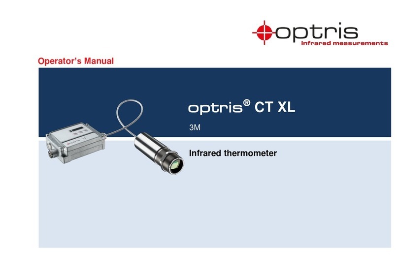
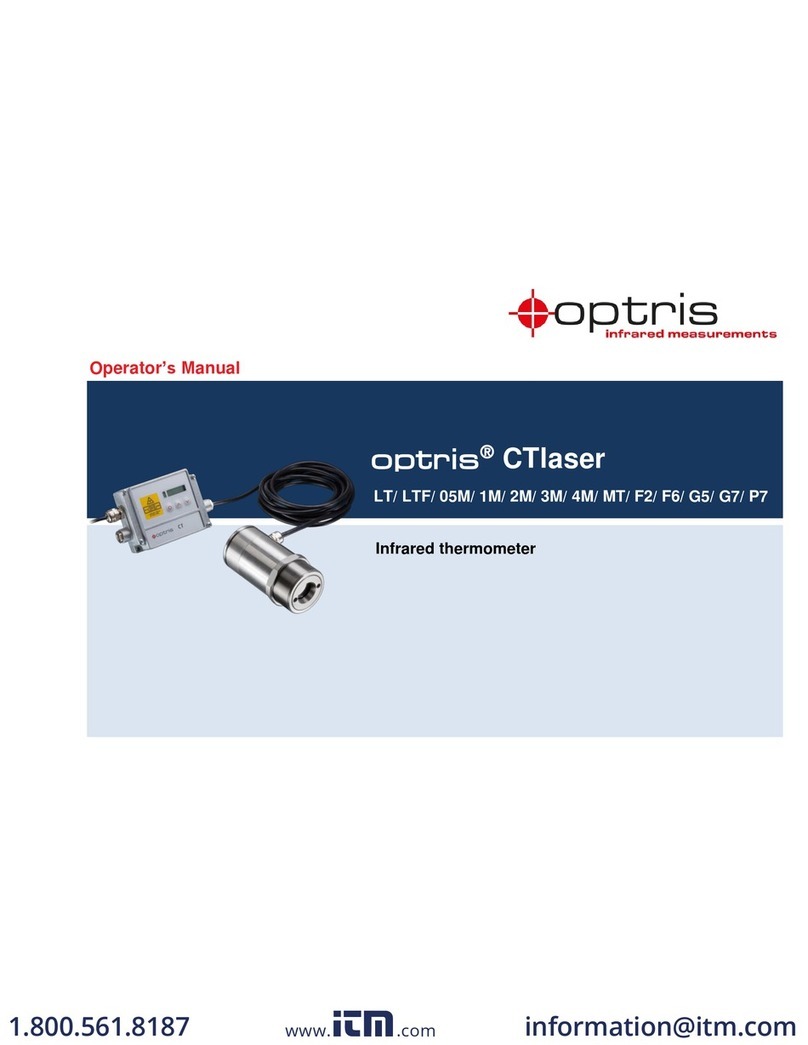
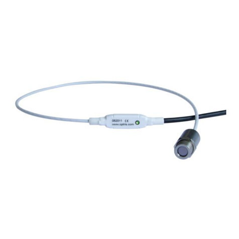
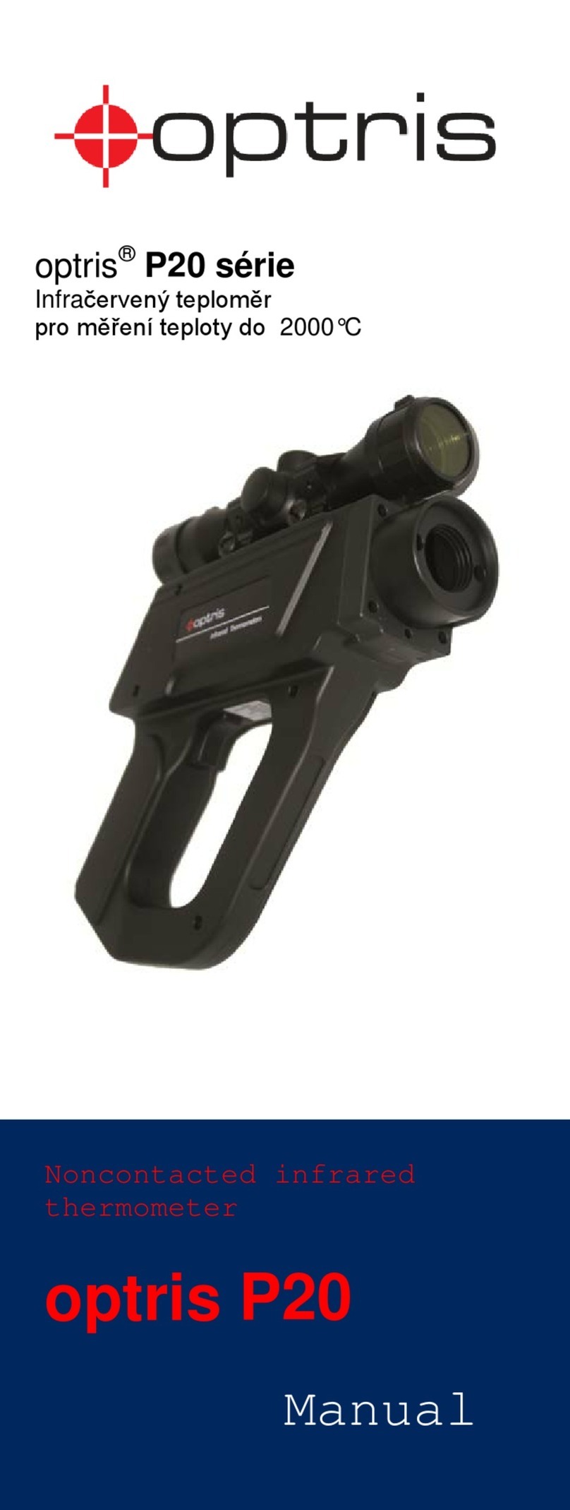
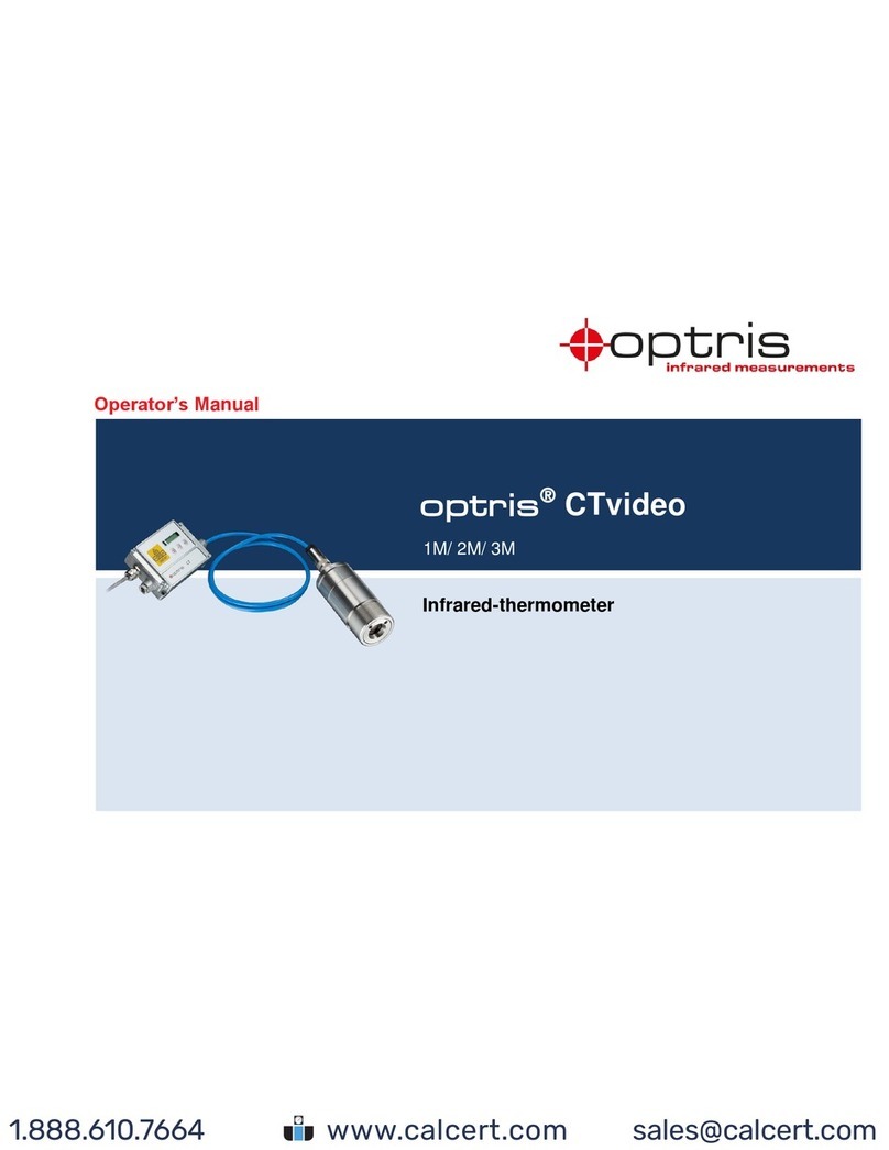
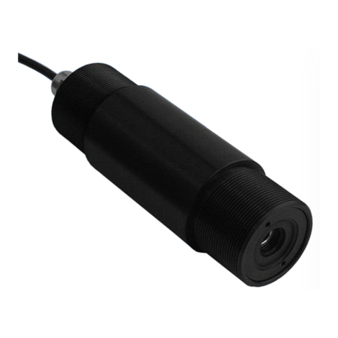
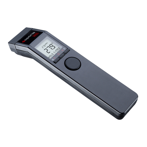
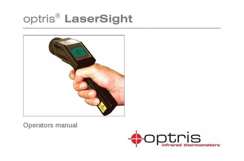
optris CompactPlus Connect User manual

Operator’s manual
optris®CompactPlus Connect
Software for Infrared-Thermometers

-2Table of contents -
Table of contents
Table of contents.................................................................. 2
Welcome!..............................................................................4
Legal disclaimer...................................................................5
1. Basics............................................................................. 6
1.1. Software installation..................................................6
1.2. Connection Sensor - Computer.................................8
1.3. RS485/ RS422..........................................................9
1.4. Easy Start-Up.........................................................10
1.5. Basic Settings.........................................................11
1.5.1. Language.......................................................11
1.5.2. Options..........................................................12
1.5.3. Diagram settings............................................13
1.6. Digital Display.........................................................14
1.7. Views......................................................................16
1.8. External Displays....................................................18
1.9. Start measurement.................................................20
1.10. Scaling of the Temperature Axis.............................22
1.11. Stop Measurement and Save Data.........................23
1.12. Measurement Configuration....................................24
1.13. Opening of Files .....................................................25
2. CTratio.......................................................................... 27
2.1. Sensor Setup CTratio.............................................27
2.2. Sensor Setup CTratio –Signal Processing.............28
2.2.1. Ratio Mode - Standard Ratio..........................29
2.2.2. Ratio Mode - Smart Ratio...............................30
2.2.3. Post Processing.............................................40
2.3. Sensor Setup CTratio –Output...............................43
2.3.1. Output 1 and 2...............................................43
2.3.2. Failsafe..........................................................46
2.4. Sensor Setup CTratio –I/O pins.............................46
2.5. Sensor Setup CTratio –Display..............................50
2.5.1. Visual Alarms.................................................50
2.5.2. Temperature unit............................................51
2.6. Sensor Setup CTratio –Advanced Settings.............52
2.6.1. RS485 Multidrop Address...............................53
2.6.2. Optical Set......................................................53
2.6.3. Calibration......................................................54
3. CT ..................................................................................57
3.1. Sensor Setup CT –Signal Processing.....................57
3.1.1. Emissivity and Transmissivity.........................58
3.1.2. Ambient Temperature Compensation .............59
3.1.3. Post Processing .............................................60
3.2. Sensor Setup CT –Output......................................65
3.2.1. Output 1 and 2................................................66
3.2.2. Failsafe...........................................................68
3.2.3. Digital Output AL2 ..........................................69
3.2.4. Relays............................................................70
3.3. I/O Pins...................................................................71
3.4. Display....................................................................74
3.4.1. Visual Alarms .................................................74
3.4.2. Temperature unit............................................75
3.5. Sensor Setup CT –Advanced Settings ...................76
3.5.1. Sensor Setup CT –Calibration.......................77
3.5.2. Manual Calibration..........................................78
3.5.3. 1 Point Calibration..........................................79
3.5.4. 2 Point Calibration..........................................80
3.5.5. USB Communication......................................81
3.5.6. RS485-Multidrop address...............................81
3.5.7. Locking the programming keys.......................82
4. CSvision........................................................................83
4.1. Setup CSvision........................................................83
4.2. Sensor Setup CSvision –Signal processing............84
4.2.1. Ratio Mode - Standard Ratio ..........................85
4.2.2. Ratio Mode - Smart Ratio...............................86
4.2.3. Post Processing .............................................95
4.3. Sensor Setup CSvision –Output.............................99
4.3.1. Output 1 and 2................................................99
Table of contents 3-
4.3.2. Failsafe........................................................ 102
4.4. Sensor Setup CSvision –I/O-Pin.......................... 102
4.5. Sensor Setup CSvision –Display..........................106
4.5.1. Visual Alarms...............................................106
4.5.2. Temperature unit..........................................107
4.6. Sensor Setup CSvision –Advanced Settings........ 108
4.6.1. RS485 Base Address...................................109
4.6.2. Field Calibration........................................... 110
4.6.3. Videosignal..................................................113
4.6.4. Automatic Snapshots................................... 114
5. Special Feature........................................................... 115
5.1. Saving the Sensor Configuration ..........................115
5.2. Smart Averaging...................................................116
5.3. Binary Chat Program............................................117
5.3.1. Additional Features.......................................119
6. Menu Overview...........................................................120
6.1. Menu: File.............................................................120
6.2. Menu: Measurement .............................................121
6.3. Menu: Device........................................................122
6.4. Menu: Diagram......................................................123
6.5. Menu: View...........................................................124
6.6. Menu: Preferences................................................126
6.7. Menu: Help............................................................126
6.8. Context Menu (right mouse button) .......................127
6.9. Context Menu [Sub menu: View]...........................128
6.10. Context-Menu [Sub menu: External Display] .........129

-4Welcome! -
Welcome!
Thank you for choosing an infrared thermometer and corresponding CompactPlus Connect software!
The sensor calculates the surface temperature based on the emitted infrared energy of objects [► Basics of
Infrared Thermometry].
Main features of CompactPlus Connect
software:
▪Temperature data analysis and
documentation
▪Automatic process control
▪Customer specific software
adjustments
▪Complete parameterization of the
device
▪Temperature display and recording
▪Videosignal (only for CSvision)

Legal disclaimer 5-
Legal disclaimer
All products are warranted against defective materials and workmanship
for a period of two (2) years from the delivery date of the original purchase,
provided such products have been under normal storage, use and service,
and in accordance with the instruction. This warranty expires in case of
inappropriate use of all delivered components.
All products not manufactured by us included in systems delivered by us
to the original purchaser carry the warranty, if any, of the particular supplier
only and we have no responsibility whatsoever for such products.
The manufacturer is not liable for any use of the software CompactPlus
Connect including data recording. The manufacturer does not carry liability
for error-free operation of the software in any hardware and operating
system.
The warranty is not expressed for possible quality changes, errors when presenting the software, occurring
defects during operation or insufficiencies in certain applications. The user is liable for any defects or data
processing insufficiencies when in using the software.
The manufacturer has no other liability inside the scope of supply other than mentioned above. The
manufacturer shall not be liable for any business loss or claim for compensation, loss of the computer software,
possible loss of data, additional costs for replacement software, claims of third parties or other occurring costs
or failures and deficits.
The software is protected by copyright and is not allowed to be changed or sold to third parties.
Note
Read the manual carefully before you start the device. The manufacturer reserves the right to change
the herein described specifications in case of technical advance of the product.
Optris GmbH
Ferdinand-Buisson-Str. 14
13127 Berlin
Germany
Phone: +49-30-500 197-0
Fax: +49-30-500 197-10
Internet: www.optris.global

-6Basics -
1. Basics
1.1. Software installation
Download the software from the Optris website.
Please start Setup.exe and follow the instructions
of the wizard until the installation is finished.
The installation wizard will place a launch icon on the desktop and in the start menu:
[Start]\Programs\CompactPlus Connect.
When using the Ethernet interface, the driver must be installed separately. This can be found in the download
package in the Driver folder (Name: Ethernet).
Note
The software can be downloaded via the Optris website under the following link:
https://www.optris.global/downloads-software
Minimum system requirements:
▪Windows 10, 11
▪USB interface
▪Hard disc with at least 30 MByte free space
▪At least 128 MByte RAM

Basics 7-
IRmobile App
The pyrometers have a direct connection to an Android smartphone or
tablet. All you have to do is download the IRmobile app for free in the Google
Play Store. This can also be done via the QR code.
Note
The IRmobile app works on most Android devices running 5.0 or higher with a micro USB or
USB-C port supporting USB-OTG (On The Go).

-8Basics -
1.2. Connection Sensor - Computer
If you connect your sensor to your PC and start the software, the following message will appear (if option Auto
Start is activated). ► Menu Preferences/ Options
Then please press the Scan button. All sensors found will be shown in a selection screen:
After the selection of a sensor you will get to the previous screen again. Here you will find now information
about the used virtual COM port (VCP), the serial number and the baud rate.
To finish please press OK. The window will be closed.
Example 1: A sensor was found. Press Select
to close the window.
Refresh starts a new search.
Example 2: Two sensors were found. Please
activate with the cursor the desired unit and after
that press the Select button to close the
window.
Refresh starts a new search.

Basics 9-
If Auto start device is activated ► Menu Preferences/ Options the measurement starts and the
temperature values will be shown in the diagram.
After the sensor selection the status line (below the time axis) shows the following information:
COMxx: Opened active COM port
CTRatio: Measuring successful communication with the connected sensor
1.3. RS485/ RS422
If a RS485 interface is used please activate the RS422 mode. Therefore you have to call this function with the
programming keys on the sensor at first (menu item: multidrop address). You will need also the RS485 module
and the RS485-USB adapter [ACCTRS485USBK].

-10 Basics -
1.4. Easy Start-Up
If you restart the software and the last used sensor is
connected to the computer and the Auto Start option is
activated ► Preferences/ Options the connection will be
made automatically (without sensor selection window).
If this option is deactivated, you must select the
corresponding device in [Menu: Device\ Scan Devices]
and press the Select button.
The button Disconnect in [Menu: Device] breaks the
connection to the sensor and closes the COM port.

Basics 11-
1.5. Basic Settings
1.5.1. Language
You can choose the desired language in the menu
[Menu: Preferences\ Language].

-12 Basics -
1.5.2. Options
The menu item [Menu: Preferences\ Options]
allows the following settings:
Auto Start
If activated, after each program start the measurement will be started
automatically (if connected sensors have been found before).
Auto Apply
If activated the changing of the settings will be directly effected
Fahrenheit
If activated, the temperature is displayed in Fahrenheit.
The further options are described under ► Stop Measurement and Save Data.

Basics 13-
1.5.3. Diagram settings
The menu item Settings [Menu: Diagram\
Settings] enables the selection of the following
diagram options:
Digital Display
Selection which signals
should be displayed as
digital display
Diagram
Selection which signals
should be displayed as
graph
Pen Width
Pen width of the
temperature graphs [1...5]
Color
Color of the temperature
graph and digital displays
Y-axis
Display of the graph on the
primary or secondary Y-
axis
Fast burst
Deactivation of all raws

-14 Basics -
1.6. Digital Display
If the sensor is connected to your computer and you start the software,
the process temperature TProc will be shown as digital display.
You can add additional displays [Menu: Diagram\ Settings]. Dependent
on the sensor type the available signals may vary.
TProc includes the current post processing functions (average, peak hold,
etc.).
The once selected displays will also appear after a restart of the
software. The size can be changed if you put the cursor on the line
beneath the display and pull it down. The buttons of the tool bar will also
be moved (depending on the display size).
The colors of the different displays are equal to the colors selected under
[Menu: Diagram\ Settings] for the corresponding temperature graphs.
►Basic Settings

Basics 15-
Overview of Digital Display
Notation
Description
TProc
Process temperature
With signal processing, including averaging
TRatio
Ratio temperature
Without signal processing, including averaging
T1
1-channel temperature
Without signal processing, including averaging
T2
2-channel temperature
Without signal processing, including averaging
TActRatio
Actual temperature of ratio
Without signal processing, without averaging
TTAct1
Actual temperature of channel 1
Without signal processing, without averaging
TTAct2
Actual temperature of channel 2
Without signal processing, without averaging
Attenuation
Signal attenuation
Signal attenuation
TDet / TInt
Head temperature
Temperature value of detector
TBox
Box temperature
Temperature of electronic box
TAvg
Average temperatur
Without signal processing, including averaging
Note
The available temperatures depend on the connected device type

Basics 17-
You can show the digital displays also separate by hiding of
selected information (e.g. title bar, menu bar, etc.) in any size
► Digital Displays and, if desired, also always on top of your
PC screen [Menu: View\ Always on top].

-18 Basics -
1.8. External Displays
By double click on one of the digital displays [Menu: View\ External Display]
you can start an external display for the respective signal. This display will
appear initially in the same color than the respective display in the software. By
drag and drop these external displays can be placed at any desired location on
the PC screen (the position of the according software display will not change).
For an easy positioning a mark will appear on the left of the display if crossed
with the cursor:
Note
To distinguish between several displays the name of the software/ instance (for multiple software
calls) as well as the signal name will be shown shortly.
There are different options available for the design of the external
displays which can be called with the right mouse button:
Border
Presenting the display with a border –in this
mode the size of the display can be changed.

Basics 19-
Transparent
Transparent presenting –useful for a
positioning of the display in front of pictures
or wallpapers.
Change color
For changing the display color.
Use contrast color
Dependent on the used background the
presenting of the display figures with
contrast color (black edging) can be useful.
Remove Display
Closes the associated external display.

-20 Basics -
1.9. Start measurement
To start a measurement, please press the Start button in the tool bar [Menu: Measurement\ Start].
Control elements of the time axis:
1
Scroll bar
2
Zoom in (increase)
3
Zoom out (decrease)
4
Whole range
5
H: Hold/ C: Continue
1
2
3
4
5
Table of contents
Other optris Thermometer manuals

optris
optris P20 LT User manual

optris
optris CTratio User manual

optris
optris CT User manual

optris
optris CT XL 3M User manual

optris
optris CT video series User manual

optris
optris MS User manual

optris
optris CTlaser LT User manual

optris
optris CTratio 1M Series User manual

optris
optris CSlaser LT User manual

optris
optris CS User manual

optris
optris LaserSight User manual

optris
optris P20 Series User manual

optris
optris CTlaser LT User manual

optris
optris LT User manual

optris
optris CX User manual

optris
optris MS Plus User manual

optris
optris CT User manual

optris
optris CSlaser LT User manual

optris
optris CTvideo 1M User manual

optris
optris CTratio User manual