Orbit 20 User manual

OWNER’S MANUAL
WARNING
Exercise can present a health risk.
Consult a physician before beginning
any exercise program with this
equipment. If you feel faint or dizzy,
immediately discontinue use of this
equipment. Serious bodily injury can
occur if this equipment is not assembled
and used correctly. Serious bodily injury
can also occur if all instructions are not
followed. Keep others and pets away
from equipment when in use. Always
make sure all bolts and nuts are
tightened prior to each use. Follow all
safety instructions in this manual.
CAUTION:
Weight on this product should not exceed 300 LBS / 136 KGS
Product May Vary Slightly
FromPictured.
v. VI
MADE IN TAIWAN
T6510

1
SAFETY INSTRUCTIONS
WARNING: To reduce the risk of serious injury, read the following Safety Instructions before using
the 3 in 1 Rower / Recumbent Bike & Pilates.
1. Read all warnings posted on the 3 in 1 Rower / Recumbent Bike & Pilates.
2. Read this Owner’s Manual and follow it carefully before using the 3 in 1 Rower / Recumbent Bike & Pilates.
3. Make sure that it is properly assembled and tightened before use.
4. Keep children away from the 3 in 1 Rower / Recumbent Bike & Pilates. Do not allow children to use or play
on the 3 in 1 Rower / Recumbent Bike & Pilates. Keep children and pets away form the 3 in 1 Rower /
Recumbent Bike & Pilates when it is in use.
5. Set up and operate the 3 in 1 Rower / Recumbent Bike & Pilates on a solid level surface. Do not position the
3 in 1 Rower / Recumbent Bike & Pilates on loose rugs or uneven surfaces.
6. Inspect the 3 in 1 Rower / Recumbent Bike & Pilates for worn or loose components prior to use.
7. Tighten / replace any loose or worn components prior to using the 3 in 1 Rower / Recumbent Bike & Pilates.
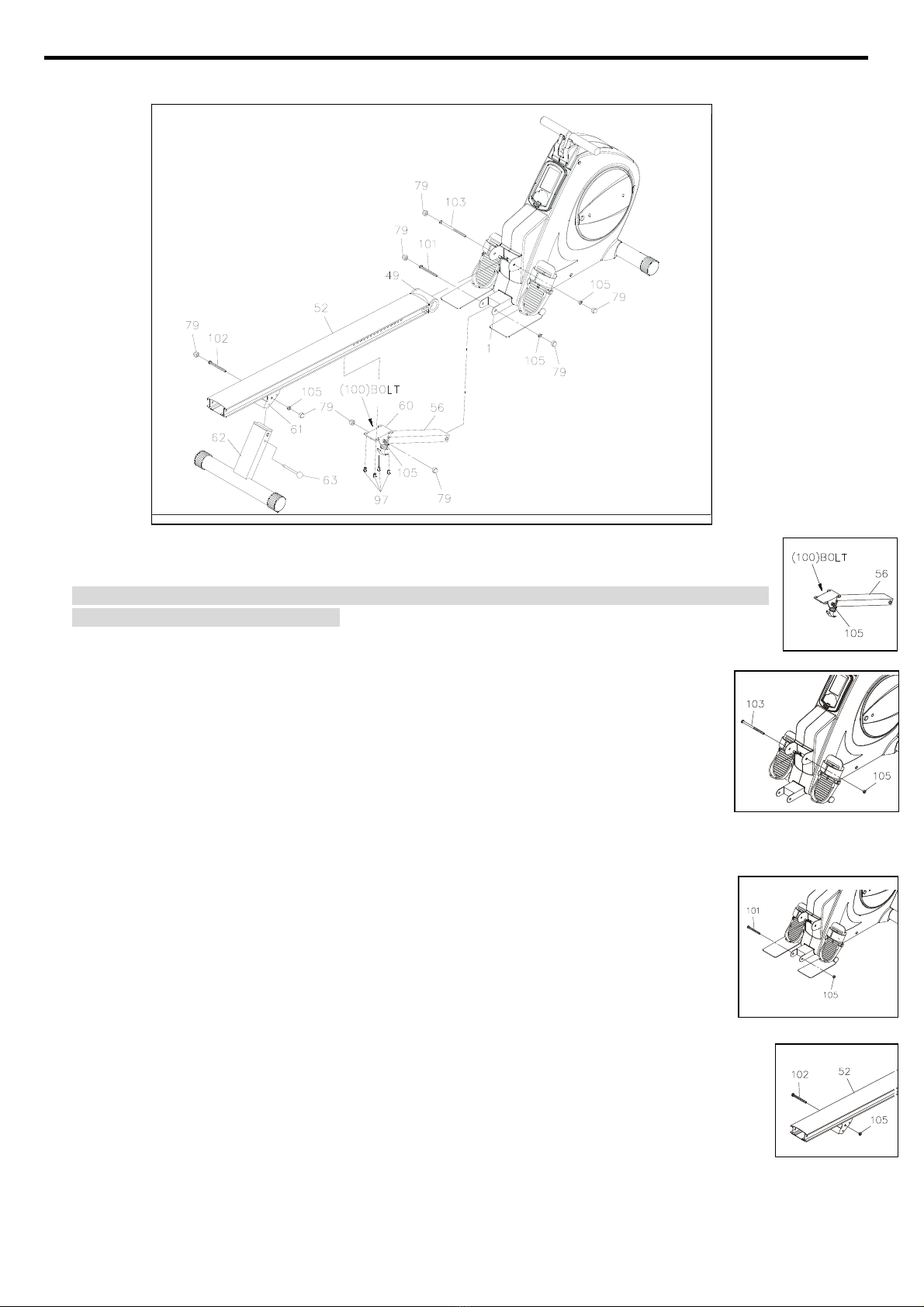
8. Make sure the Rear Support(62) is locked properly with the Pull Pin (63) before using 3 in 1 Rower /
Recumbent Bike & Pilates.
9. Make sure the Rail(52) is locked properly by the Release Knob(59) located on the Support Tube(56) when
in storage.
10. Keep fingers clear of all pinch points when folding and unfolding the 3 in 1 Rower / Recumbent Bike &
Pilate.
11. Lock seat in position with at least one adjustment hole visible in front of the seat before lifting rail to
storage position. This will prevent the seat from damaging the covers.
12. Consult a physician prior to commencing an exercise program. If, at any time during exercise, you feel faint,
dizzy, or experience pain, stop and consult your physician.
13. Follow your physician’s recommendations in developing your own personal fitness program.
14. Always choose the workout which best fits your physical strength and flexibility level. Know your limits and
train within them. Always use common sense when exercise.
15. Do not wear loose or dangling clothing while using the 3 in 1 Rower / Recumbent Bike & Pilates.
16. Never exercise in bare feet or socks; always wear correct footwear, such as running, walking, or
cross-training shoes. Be sure that they fit well, provide foot support and feature non-skid rubber soles.
17. Be careful to maintain your balance while using, mounting, dismounting, or assembling the 3 in 1 Rower /
Recumbent Bike & Pilates, loss of balance may result in a fall and serious bodily injury.
18. The 3 in 1 Rower / Recumbent Bike & Pilates should not be used by persons weighing over 300 lbs / 136
kgs.
19. The 3 in 1 Rower / Recumbent Bike & Pilates should be used by only one person at a time.
20. The 3 in 1 Rower / Recumbent Bike & Pilates is for consumer use only. It is not for use in public or
semipublic facilities.
WARNING: Before starting any exercise or conditioning program you should consult with your personal
physician to see if you require a complete physical exam. This is especially important if you are over the age of
35, have never exercised before, are pregnant, or suffer from any illness. READ AND FOLLOW THE SAFETY
PRECAUTIONS. FAILURE TO FOLLOW THESE INSTRUCTIONS CAN RESULT IN SERIOUS BODILY
INJURY.

2
HAREWARE INDETIFICATION CHART
This chart is provided to help identify the hardware used in the assembly process. Place the washers, the end of the bolts,
or screws on the circles to check for the correct diameter. Use the small scale to check the length of the bolts and screws.
NOTICE: The length of all bolts and screws except those with flat heads is measured from
below the head to the end of the bolt or screw. Flat head bolts and screws
are measured from the top of the head to the end of the bolt or screw.
After unpacking the unit, open the hardware bag and make sure that you have all the following items. Some hardware
may be already attached to the part.
Part No. and Description Qty
63 Pull Pin 1
78 Round Plug 25mm 2
79 Nut Cap (M10) 8
81 Bolt, Socket Head (M8x1.25x70mm) 2
89 spring washer 2
94 Bolt, Button Head (M8x 1.25x 15mm) 2
95 Bolt, Round Head (M6x 1 x 15mm) 4

3
96 Bolt, Round Head (M6x1x30mm) 4
97 Bolt, Hex Head (M8x1.25x16mm) 4
109 Large Washer (M8xφ23) 2
Allen Wrench (M6) 2
Hex Wrench 2
Combination Wrench 1

4
ASSEMBLY INSTRUCTIONS
Place all parts form the box in a cleared area and position them on the floor in front of you. Remove all packing
materials from your area and place them back into the box. Do not dispose of the packing materials until
assembly is completed.
STEP 1: There is a “R” decal on one end of the FRONT STABILIZER(2). Attach the FRONT STABILIZER(2)
onto the MAIN FRAME(1) with the “R” decal end at right side and secure with 2pcs Bolt, Socket
Head(M8x70mm)(81) and 2pcs SPRING WASHER M8(89).
STEP 2:
a. NOTE: 1pcs BOLT, BUTTON HEAD(M8x15mm)(94) will already be pre-attached on the
middle of the STOPPER TUBE(48).
b. Remove 1pcs BOLT, BUTTON HEAD(M8x15mm)(94) from the middle of the STOPPER
TUBE(48).
c. Insert the STOPPER TUBE(48) through the MAIN FRAME(1) and secure with 1pcs BOLT, BUTTON
HEAD(M8x15mm)(94).
STEP3: Place the RIGHT PILATES PEDAL(116R) onto the STOPPER TUBE(48). Press 1pcs Round Plug
25mm(78) into the end of STOPPER TUBE(48); repeat the same step in the left side. NOTE: The
PEDAL STRAPS(47) are pre-assembled to the FOOT PEDALS(46). The pedal and strap assembly for
the left side has a “L” decal. The pedal and strap assembly for the right side has a “R” decal.
STEP 4: Insert the PEDAL SHAFT(44) through the MAIN FRAME(1). Place the RIGHT FOOT PEDAL
ASSEMBLY(46R) onto the right end of the PEDAL SHAFT(44) and place the LEFT FOOT PEDAL
ASSEMBLY(46L) onto the left end. Secure the FOOT PEDALS with 2pcs BUTTON HEAD BOLTS
(M8x15mm)(94) and 2pcs LARGE WASHERS(M8)(109) at both ends of the PEDAL SHAFT(44).
NOTE: You need to use two Allen Wrenches to tighten the BUTTON HEAD BOLTS(M8x15mm)(94)
at both ends of the PEDAL SHAFT(44) at the same time.

5
ASSEMBLY INSTRUCTIONS
STEP 5:
a. Attach the SUPPORT BRACKET(60) onto the RAIL(52) with 4pcs HEX BOLTS (M8x16mm)(97).
b. Press the NUT CAPS(79) onto the NYLOCK NUT(M10)(105) and the HEX BOLT(M10x75mm) (100).
NOTE: 1pcs NYLOCK NUT(M10)(105) and 1pcs HEX BOLT(M10x75mm) (100) already fully secured
on both side of the Support Tube (56).
STEP 6:
a. NOTE: 1pcs HEX BOLT (M10x125mm)(103) and 1pcs NYLOCK NUT(M10)(105) will already
be pre-attached on both side of the Main Frame.
b. Remove 1pcs HEX BOLT (M10x125mm)(103) and 1pcs NYLOCK NUT(M10)(105) from both
side of the Main Frame.
c. Attach the RAIL(52) onto the MAIN FRAME(1) by sliding the RAIL PIVOT(49) into the bracket
on the MAIN FRAME(1) and securing with 1pcs HEX BOLT (M10x125mm)(103) and 1pcs
NYLOCK NUT(M10)(105). Press the NUT CAPS(79) onto the HEX BOLT (M10x125mm)(103)
and NYLOCK NUT(M10)(105).
STEP 7:
a. NOTE: 1pcs HEX BOLT (M10x85mm)(101) and 1pcs NYLOCK NUT(M10)(105) will already be
pre-attached on both side of the Main Frame.
b. Remove 1pcs HEX BOLT (M10x85mm)(101) and 1pcs NYLOCK NUT(M10)(105) from both
side of the Main Frame.
c. Connect the lower end of the SUPPORT TUBE(56) to the MAIN FRAME(1) with 1pcs HEX
BOLT (M10x85mm)(101) and 1pcs NYLOCK NUT(M10)(105). Press the NUT CAPS(79) onto
the HEX BOLT(M10x85mm)(101) and the NYLOCK NUT(M10)(105).
STEP 8:
a. NOTE: 1pcs BOLT, HEX HEAD(M10x95mm)(102) and 1pcs NYLOCK NUT(M10)(105) will already
be pre-attached on the back of the Rail (52).
b. Remove 1pcs BOLT, HEX HEAD(M10x95mm)(102) and 1pcs NYLOCK NUT(M10)(105) from the
back of the Rail (52).
c. Attach the REAR SUPPORT(62) into the REAR SUPPORT BRACKET(61) located on the RAIL(52)
with 1pcs BOLT, HEX HEAD(M10x95mm)(102) and1pcs NYLOCK NUT(M10)(105). Lock the REAR
SUPPORT(62) in position with the PULL PIN(63). Press the NUT CAPS(79) onto the BOLT, HEX HEAD
(M10x95mm)(102) and the NULOCK NUT(M10)(105).

6
ASSEMBLY INSTRUCTIONS
NOTE: Be careful not to damage the PULSE SENSOR WIRES(73,74) while doing assembly STEP 9
to STEP 10.
STEP 9:
a. NOTE: 4pcs BUTTON HEAD BOLTS(M8x12mm)(114) will already be
pre-attached on the SEAT HANDRAIL(70).
b. Remove 4pcs BUTTON HEAD BOLTS(M8x12mm)(114) from the SEAT
HANDRAIL(70).
c. Attach the SEAT HANDRAIL(70) onto the SEAT CARRIAGE(64) with 4pcs BUTTON HEAD
BOLTS(M8x12mm)(114).
STEP 10: Attach the SEAT(68) onto the SEAT CARRIAGE(64) with 4pcs BOLT, ROUND HEAD
(M6x1x15mm)(95). Attach the BACK CUSHION(69) onto the SEAT CARRIAGE(64) with
4pcs HEX HEAD BOLTS (M6x1x30mm)(96).
STEP 11:
a. Turn the knob of the SPRING PIN(67) counter-clockwise and lock the knob in the release position,
refer to the inset drawing.
b. Slide the SEAT CARRIAGE ASSEMBLY(64) onto the RAIL(52). Press the RAIL CAP(55) into the
back end of the RAIL(52).
c. NOTE: 1pcs STOPPER BOLT(54) and 1pcs STOPPER(53) will already be
pre-attached at the end of the RAIL (52).
d. Remove 1pcs STOPPER BOLT(54) and 1pcs STOPPER(53) from the end of
the RAIL (52).
e. Insert the STOPPER BOLT(54) through the RAIL(52) and RAIL CAP(55) to bolt
them together with the STOPPER(53). Please verify that the other STOPPER
BOLT(54) at the front end of RAIL(52) was assembled at the factory.

7
ASSEMBLY INSTRUCTIONS NOTE:
a. The RIGHT PEDAL(41)
has Rdecal stamped
on the end of the right
pedal shaft. The
RIGHT PEDAL(41) has
right hand threads and
is tightened by turning
clockwise.
b. The LEFT PEDAL(39)
has Ldecal stamped
on the end of the left
pedal shaft. The LEFT
PEDAL(39) has left
hand threads and is
tightened by turning
counter-clockwise.
STEP 12:
a. Thread the RIGHT PEDAL(41) onto the RIGHT CRANK(37) located at inside of the CRANK COVER(35) as
the photo shown. Tighten the pedal securely.
b. Select the RIGHT PEDAL STRAP(42) which has R decal marked on the bottom side of the strap. Snap the
three hole end onto the inside edge of the RIGHT PEDAL(41). Snap the other end onto the outside edge of
the RIGHT PEDAL(41) with the R decal mark on the bottom of the RIGHT PEDAL STRAP(42). Select
adjustment holes which allow your foot to be easily removed from the pedals. Do the same way on the left
side.
STEP 13: Refer to the upper inset drawing. Plug the PULSE SENSOR WIRE(73) into the preset socket of the
PULSE COIL WIRE(74) located on the SEAT CARRIAGE(64). Plug the PULSE COIL WIRE(74) into
the preset socket of PULSE CONNECTION WIRE(75) located on the bracket on the MAIN
FRAME(1).
STEP 14: Refer to the lower inset drawing. Connect the ADAPTER(119) to the connector located on the base
of the Main Frame(1). Plug the ADAPTER(119) into an electrical outlet.
STEP 15:
a. A bottle of silicone is packed together with user’s manual.
b. Gently apply the silicone to the rollers sliding path
(inner upper side and inner bottom side) on the aluminum rail.
Note: Apply liberally but be cautious not to spill the lubricant as
applied surfaces will become very slippery. To clean spills use
warm soapy water, repeat if necessary.
c. Then slowly slide the Seat forward and backward for a few seconds
allowing the lubricant spread evenly on the rollers sliding path on
aluminum rail.
Lubricate the silicone to
the rollers sliding path on
the aluminum rail.

OPERATIONAL INSTRUCTIONS
RECUMBENT BIKE MODE AND ROWER MODE
Your 3 in 1 Rower, Recumbent Bike & Pilates can be used in the Recumbent Bike mode or the Rower
mode.
When the SPRING PIN(67) locks the SEATASSEMBLY to the RAIL(52), the 3 in 1 Rower,
Recumbent Bike & Pilates is in the Recumbent Bike mode.
When the SPRING PIN(67) is in the Release position, the SEATASSEMBLY is not locked to the
RAIL(52) and the item is in the Rower mode.
RECUMBENT BIKE MODE:
a. Make sure the seat is in the release
position.
b. Place you feet on the Left and Right
PEDALS (39, 41) and adjust the
proper seat position.
c. Pull the knob on the SPRING PIN(67),
turn it clockwise and release the knob
to allow it to lock the seat in position.
ROWER MODE:
a. To release the Seat, pull the knob on
the SPRING PIN(67) and turn it
counter-clockwise to lock it in the
release position. Refer to the inset drawing.
b. The above process will allow the SEAT ASSEMBLY(64) to slide freely on the RAIL(52).
c. To workout, sit on the seat, place your feet on the fixed FOOT PEDALS(46) and pull on the
HANDLEBAR(25).
NOTE: If the FRONT STABILIZER(2) raises off the floor during use, adjust the STAND(43) to a higher
position.
CAUTION: Always verify that the SPRING PIN (67) is in the correct position before you begin your
workout.

9
BODY MOVEMENT EXERCISE
RECUMBENT EXERCISE BUTTOCKS EXERCISE
BICEP CURL EXERCISE
BACK & ABDOMINAL EXERCISE
ROWER EXERCISE
TRICEPPULL EXERCISE
LEG EXTENSION EXERCISE LEG STRETCH EXERCISE
Be sure to step on the iron PILATES PEDAL

10
STORAGE
1. To store the 3 in 1 Rower, Recumbent Bike & Pilates simply keep it in a clean dry place.
2. To avoid damage to the electronics meter, remove the batteries before storing the 3 in 1 Rower,
Recumbent Bike & Pilate for one year or more.
3. Move the 3 in 1 Rower, Recumbent Bike & Pilate with the moving wheels on the Front Stand.
Grasp the Rail Cap to move the 3 in 1 Rower, Recumbent Bike & Pilate. Do not use the Seat to
move the 3 in 1 Rower, Recumbent Bike & Pilate. The Seat will move and the Seat Carriage may
pinch your hand or fingers.
4. Follow the following process to fold the 3 in 1 Rower, Recumbent Bike & Pilate as illustrated for
easy storage.
a. Adjust and lock the seat in position with at least one adjustment hole visible in front of the seat.
NOTE: This will prevent the seat from damaging the covers.
b. Remove the PULL PIN(63) and swing the REAR SUPPORT(62) toward the front.
NOTE: This will allow you to pull out the RELEASE KNOB(59) easily.
c. Pull out the RELEASE KNOB(59) and fold up the RAIL(52). Make sure the RAIL(52) is locked
securely in folded position by using RELEASE KNOB(59).
d. Lock the REAR SUPPORT(62) in folded position with the PULL PIN(63).
UNFOLD THE 3 IN 1 ROWER, RECUMBENT BIKE & PILATES
a. Pull out the RELEASE KNOB(59) and unfold the RAIL(52). Make sure the RAIL(52) is locked
securely in the unfolded position by using RELEASE KNOB(59).
b. Remove the PULL PIN(63) and swing the REAR SUPPORT(62) backward, then lock the
REAR SUPPORT(62) in position with the PULL PIN(63).
A
C
D

11
“CONSOLE INSTRUCTIONS”
Program List
MANUAL PROGRAM
P1 ROLLINGPROGRAM
P2 VALLEYPROGRAM
P3 FAT BURN PROGRAM
P4 RAMP PROGRAM
P5 RANOM PROGRAM
POWER ON
a. Make sure the item’s adaptor is correctly plugged
into the socket
b. Rowing or pressing any keys to active the console.
The console display will then light up with a short
beep sound, indicating the console will be ready for
use
POWER OFF
The console would automatically shut off after 4
minutes of inactivity

12
“CONSOLE INSTRUCTIONS – CONSOLE BUTTONS ”
a. Press START\STOP to begin your exercise
b. Press
START\STOP again to stop and pause all functions during your exercise
program. All the date on the display will then freeze.
c. Press START\STOP again to resume the program and all the date displayed will
continue until the program has finished.
d. HOLD TO RESET function: Continue pressing START\STOP, all the date will return to
0 and the console will return to POWER ON status
a. Press MODE to confirm the function mode (TIME, DISTANCE, CALORIES, TARTE
HEART REAT)
b. During workout, press MODE to review each program function (TIME, DISTANCE,
CALORIES, TARTE HEART REAT)
Press UP to increase the values of the program function (TIME, DISTANCE, CALORIES,
TARTE HEART REAT)
Press DOWN to increase the values of the program function (TIME, DISTANCE,
CALORIES, TARTE HEART REAT)
a. PULSE RECOVERY button measures how quickly you
return to a resting hear rate after exercising. You could
use this button to measure improvement as you get into
shape
b. The console will monitor your pulse for 60 seconds and
calculate a HEART RATE RECOVERY value from F1.0
to F6.0. F1.0 is best; F6.0 is worst (For Reference Only)
c. The readout should only be used as a comparison
between workouts. It’s recommended to use right after
any aerobic exercise. Stop exercising before starting
the function.
d. Your pulse will be displayed approximately few seconds
after the heart symbol “ ” is displayed
e. To leave the pulse recovery program, press START\STOP for a few seconds. After a
short beep sound, the console would turn into the initial POWER ON status
NOTE:
The EAR CLIP PULSE WIRE or CHEST BELT is an optional
feature. Make sure whether the item is equipped with ear clip
pulse wire socket located on the METER(32) or the console has
a built-in receiver feature. Wear ear clip or chest belt before
testing the result of your HEART RATE RECOVERY. If you
don’t wear ear clip or chest belt, the console’s main screen
would show “F6.0” after the console counts down to zero, which
means the EAR CLIP PULSE WIRE or CHEST BELT won’t be
able to pick up the signals. Press any keys to stop the long
beep sound, then press PULSE RECOVERY button again and
make sure to wear ear clip or chest belt this time

13
“CONSOLE INSTRUCTIONS”– CONSOLE FUNCTIONS”
a. During workout, press MODE button until “SCAN” shows on the screen.
b. The console would scan automatically from TIME, SPM, COUNT, CAL in order at 5 second
intervals
a. Count Up: If a target time was not selected, TIME will count up from 0:00 to maximum 99:59
minutes
b. Count Down: If you have set the target TIME (1:00 TO 99:00; 1 MINUTE INCREMENT), the
console will count down from that selected target time down to 0:00
Display range: 0 ~999 km/hr
a. Count Up: If a target distance was not selected, this would measure the total distance from 0:00
to 999 km/hr
b. Count Down: If you have set the target distance, the console will count down from that selected
target distance down to 0
a. Count Up: If target calories were not selected, this measures total calories your body burned
during exercise
b. Count Down: If you have set the preference value of CALORIES (10 TO 9990 KCAL; 10 KCAL
INCREMENT), the console will count down from that selected target calories down to 0
The EAR CLIP PULSE WIRE or CHEST BELT is an optional feature. Make sure whether the item is
equipped with ear clip pulse wire socket located on the METER(32) or the console has a built-in
receiver feature. Wear ear clip or chest belt before starting exercise. If you don’t wear ear clip or
chest belt, the value of Pulse would show “P”, which means the EAR CLIP PULSE WIRE or CHEST
BELT won’t be able to pick up the signals. To review the current value of your pulse, always make
sure to wear ear clip or chest belt
When “ ” shows on the console’s main screen, indicating the console is in START status
When “ ” shows on the console’s main screen, indicating the console is in PAUSE status

14
POWER ON status
“CONSOLE INSTRUCTIONS”– MANUAL PROGRAM & P1 ~ P5”
“1” Prior information: Press any button on the console or begin rowing to turn on the console
a. Make sure that the power cord is properly plugged into the socket
b. The console would automatically shut off after 4 minutes of inactivity
c. Press any button on the console or begin rowing to turn on the console.After a few seconds, the console will then light
up with a short beet sound, indicating the console will be ready for use
“2” Prior information: ” START\STOP” button, an easy way to reset and enter into POWER ON
status
Continue pressing START\STOP a few seconds, all the date will
reset to the initial value and the console will return to POWER ON
status
“3” Normal way to operate MANUAL AND PROGRAM (P1~P5)
“A.“ENTER MANUAL AND PROGRAM (P1~P5)”
a.START\STOP button:
To enter the preference program (MANUAL, or P1….P5), pressing
START\STOP button to pause the current program
b.UP or DOWN button:
With the display flashing “MANUAL, or PROGRAM (P1~P5)”, press UP or DOWN button to select
MANUAL or PROGRAM (P1~P5)
c. MODE button:
Press MODE button to confirm and enter MANUAL or PROGRAM (P1~P5)
MANUAL PROGRAM
P1 ROLLINGPROGRAM
P2 VALLEYPROGRAM
P3 FAT BURN PROGRAM
P4 RAMP PROGRAM
P5 RANOM PROGRAM

15
“CONSOLE INSTRUCTIONS”– MANUAL PROGRAM & P1 ~ P5”
“B. SET THE DESIRED TIME
UP or DOWN button: a. After pressing the MODE button to enter into MANUAL or PROGRAM (P1~P5), the
TIME function mode will appear with the display flashing “0:00”
b. Use
UP or DOWN buttons to set the desired TIME (1:00 TO 99:00; 1 MINUTE
INCREMENT) NOTE: If there is no need to set the desired TIME, press MODE button to
enter the COUNT function mode
c. Press MODE button to confirm TIME value and enter the COUNT function mode to set the
value of the COUNT
NOTE for TIME:
Count Up: If a target time was not selected, TIME will count up from 0:00 to maximum 99:59 minutes
Count Down: If you have set the target TIME (1:00 TO 99:00; 1 MINUTE INCREMENT), the console will count down
from that selected target time down to 0:00
“C. SET THE DESIRED DISTANCE VALUE
UP or DOWN button:
a. Use
UP or DOWN buttons to set the desired DISTANCE (10 TO 999 KM/HR; 1 KM/HR
INCREMENT) NOTE: If there is no need to set the desired DISTANCE, press MODE button
to enter the CALORIES function mode
b. Press
MODE button to confirm DISTANCE value and enter the CALORIES function mode
to set the value of the CALORIES
NOTE for DISTANCE:
Count Up: If a target distance was not selected, this would measure the total distance from 0:00 to 999 km/hr
Count Down: If you have set the target distance, the console will count down from that selected target distance down
to 0
“D. SET THE DESIRED CALORIES”
UP or DOWN button:
a. Use
UP or DOWN buttons to set the desired CALORIES (10 TO 9990 KCAL; 10 KCAL
INCREMENT) NOTE: If there is no need to set the desired CALORIES, press MODE button
to enter the TARGET HEART RATE function mode
b. Press
MODE button to confirm CALORIES value and enter the TARGET HEART RATE
function mode to set the value of the TARGET HEART RATE/PULSE LIMIT
NOTE for CALORIES:
Count Up: If target calories was not selected, this would measure total calories burned during exercise
Count Down: If you have set the preference value of CALORIES (10 TO 9990 KCAL; 10 KCAL INCREMENT), the
console will count down from that selected value down to 0

16
“CONSOLE INSTRUCTIONS”– MANUAL PROGRAM & P1 ~ P5”
“F. SET THE TARGET HEART RATE/PULSE LIMIT
UP or DOWN button:
a. Use
UP or DOWN buttons to set the desired TARGET HEART RATE/PULSE LIMIT (90 TO
220BPM (BEATS PER MINUTE); 1 BPM INCREMENT) NOTE: If there is no need to set the
desired TARGET HEART RATE/PULSE LIMIT, press MODE button to finish all the setting
function (TIME,COUNT, CAL, TARGE HEART RATE/PULSE LIMIT) value
b. Press MODE button to confirm TARGET HEART RATE/PULSE LIMIT value and finish all
the setting function value to start exercise
NOTE for TIME:
The EAR CLIP PULSE WIRE or CHEST BELT is an optional feature. Make sure whether the item is equipped with
ear clip pulse wire socket located on the METER(32) or the console has a built-in receiver feature. Wear ear clip or
chest belt before starting exercise. If you don’t wear ear clip or chest belt, the value of Pulse would show “P”, which
means the EAR CLIP PULSE WIRE or CHEST BELT won’t be able to pick up the signals. To review the current
value of your pulse, always make sure to wear ear clip or chest belt
The console will monitor your pulse and compare the value of the TARGET HEART RATE you choose ((90 TO
220BPM (BEATS PER MINUTE)). The console will keep emitting short beep sounds to warn you to slow down or
lower the torque/resistance level if your actual pulse value is greater than TARGET HEART RATE value
“E. START EXERCISE”
START\STOP button: Press START/ PAUSE to begin exercise. “START” would then
appear to the screen
“G. DURING WORKOUT, SET THE TORQUE/RESISTANCE LEVEL TO MATCH YOUR WORKOUT GOAL”
UP or DOWN button: You can change the torque/tension level (from 1 to 8 levels) at
any time during workout by pressing UP or DOWN button

17
TROUBLE SHOOTING
PROBLEM POSSIBLE CAUSE SOLUTION
E1 No speed signal
1) Review the Assembly Instructions and check that all the Computer Plugs and
Sockets are FIRMLY and correctly connected.
2) Review the Bike’s Magnetic Resistance System to ensure that it is set correctly and
thy be at it can freely be adjusted. A symptom of the previous problem is the Motor will
struggle to adjust the resistance and will start making an abnormal sound. If this
happens the Motor may already be damaged by some kind of interference.After freeing
the interference the Motor will have to be checked that it still correctly.
3) Motor Problems
a. Symptoms include an unusually loud noise come from the Motor, which means
Gears are Not meshing correctly. Try reversing the resistance and try again.
b. If the Motor fails to move at all then please recheck as per Solution.
4) above. If this fails then Replace the Motor.
E2 The Computer cannot
interface with the IC
Chip.
Disconnect theAdaptor and/or remove the Batteries.
Reconnect theAdaptor and/or the batteries. This will REBOOT the IC Chip and may
help the Computer interface with the IC Chip.
Remove and reinsert the IC Chip.
If reinsertion fails then Replace the IC chip with a New IC chip.
E3
When analyzing body
fat, the first 8
seconds has none
heart detection,
please check under.
Both hands have been firmly hold on to handgrips.
Confirm you have holding handgrip firmly.
E5 Auto-tension (Count)
is not disconnect
from zero point.
1) Review the Bike’s Magnetic Resistance System to ensure that it is set correctly and
thy be at it can freely be adjusted. A symptom of the previous problem is the Motor
will struggle to adjust the resistance and will start making an abnormal sound. If this
happens the Motor may already be damaged by some kind of interference. After
freeing the interference the Motor will have to be checked that it still correctly.
2) Motor Problems
a. Symptoms include an unusually loud noise coming from the Motor, which means
the Gears are NOT meshing correctly. Try reversing the resistance and try again.
b. If the Motor fails to move at all then please recheck as per Solution.
3) above. If this fails then Replace the Motor.
No Hand
Pulse Signal
or incorrect
Hand Pulse
Signal
The Computer is
NOT receiving a
Pulse Signal.
Check that the Hand Pulse Plugs are FIRMLY inserted into the Sockets.
The Computer is
receiving a faint of
Intermittent Pulse
Signal.
1)The Hand Pulse Sensors will NOT operate correctly if your skin is extremely dry
moisten your hands with a little water and try again.
2) The Hand Pulse Sensors are designed to be held firmly, if you move your hands
while exercising then the computer may receive an intermittent Pulse Signal. Avoid
moving your hands while exercising and hold the Hand Pulse Sensors firmly while
exercising. If you do move your hands while exercising give the Computer a few
seconds to resample and display your correct Pulse Heart Rate.
3) Clean the Hand Pulse Sensors to ensure a good contact between your body and the
Pulse Sensors.
4) Remove the Hand Pulse Sensors in order to check that the Spade Terminals are
correctly attached.
After completing all of the above Checks. If the problem still exists then please contact
your dealer.
The Computer is
faulty. Replace the Computer by contacting your dealer.

18
PROBLEM POSSIBLE CAUSE SOLUTION
The LCD
Screen does
NOT Display
anything.
You have the wrong
Adaptor or the wrong
Batteries?
Check that the Batteries or theAdaptor Specifications coincide with Instruction Manual
Specifications.
The Mains Power
switch is turned off? Check that the Mains Power is switched on and is indeed supplying power.
The Adaptor is not
plugged in? Check that the Adaptor is correctly connected to the Main Power Socket and is
correctly connected to the Computer.
The Batteries are
missing?
The Batteries are
inserted the wrong
way around?
Check to make sure there are Batteries installed.
Check that the Batteries are inserted the correct way around and that they are in the
correct series(i.e. -+)
The Computer is
faulty. Replace the Computer by contacting your dealer.
The Speed
Display Show
O.
The Computer isn’t
receiving a signal
from the Speed
Sensor?
1) Check that the Sensor Magnet is correctly fitted and passes in front of the Sensor.
2) Check the gap between Speed Sensor and the Magnet is correct 5mm or less.
3) Check that all the Computer Plugs and Sockets are FIRMLY and correctly
connected.
4) Check that the Computer Wires are not damaged.
The Sensor is faulty If all these Checks fail, then replace the Sensor.
The Computer is
faulty Replace the Computer by contacting your dealer.
The LCD
Screen
Partially
Displays.
The connection
between the Circuit
Board and the LCD
Screen Membrane is
loose, gently press
down on the LCD
Screen, if the LCD
Screen Partial
Display disappears
then it is a connection
problem.
Check that the circuit Board is securely fastened to the Computer Case, retighten the
Screw. Take care NOT to over tighten them as this may destroy the Circuit Board. Firm
is good when you meet resistance STOP.
The connection
between the Circuit
Board and the LCD
Screen Membrane is
Misaligned. If this is
the problem you
might be able to see
that the LCD Screen
is on a slight angle
and NOT inline or
parallel with the
Computer Cases.
Open that Computer Case, remove the Circuit Board Screws, gently remove the Circuit
Board, realign the LCD Screen and/or the Membrane, reassemble the LCD Screen
and/or the Membrane taking care not to bump or knock the Membrane out of alignment
before the Circuit Board Screws are tight.
Reinsert the Circuit. Board Screws and tighten them taking care NOT to over tighten
them as this may destroy the Circuit Board. Firm is good when you meet resistance
STOP.
The Computer is
faulty Replace the Computer by contacting your dealer.

19
CONDITIONING GUIDELINES
How you begin your exercise program depends on your physical condition. If you have been inactive
for several years, or are severely overweight, you must slowly and increase your time on the item
gradually: a few minutes per workout.
Initially, you may be able to exercise only for a few minutes in your target zone, however, your aerobic
fitness will improve over the next six to eight weeks. Don’t be discouraged if it takes longer. It’s
important to work at your own pace. Ultimately, you’ll be able to exercise continuously for 30 minutes.
The better your aerobic fitness, the harder you will have to work to stay in your target zone. Please
remember these essentials:
˙Have your doctor review your training and diet programs to advise you of a workout routine you
should adopt.
˙Begin your training program slowly with realistic goals that have been set by you and your doctor.
˙Monitor your pulse frequently. Establish your target heart rate base on your age and condition.
˙Set up your item a flat, even surface at least 3 feet from walls and furniture.
EXERCISE INTENSITY
To maximize the benefits of exercising, it is important to exercise with the proper intensity. The proper
intensity level can be found by using your heart rate as a guide. For effective aerobic exercise, your
heart rate should be maintained at a level between 70% and 85% of your maximum heart rate as you
exercise. This is known as your target zone. You can find your target zone in the table below. Target
zones are listed for both unconditioned and conditioned persons according to age.
During the first few months of your exercise program, keep your
heart rate near the low end of your target zone as you exercise.
After a few months, your heart rate can be increased gradually
until it is near the middle of your target zone as you exercise.
To measure your heart rate manually,
stop exercising but continue moving
your legs or walking around and place
two fingers on your wrist. Take a
six-second heartbeat count and
multiply the results by 10 to find your
heart rate. For example, if your six-second heartbeat count is 14,
your heart rate is 140 beats per minute. (A six-second count is
used because your heart rate will drop rapidly when you stop
exercising.) Adjust the intensity of your exercise until your heart
rate is at the proper level.
Other manuals for 20
1
This manual suits for next models
1
Table of contents
Other Orbit Fitness Equipment manuals

Orbit
Orbit OBB007 User manual

Orbit
Orbit Ergo 6.0 User manual

Orbit
Orbit MAX5 User manual

Orbit
Orbit OBRPR5 User manual

Orbit
Orbit Apex II OSP610 User manual

Orbit
Orbit OBB007-LAT User manual

Orbit
Orbit ArizonaMist User manual

Orbit
Orbit OBA2123A User manual

Orbit
Orbit AF1005 User manual

Orbit
Orbit AF1005 User manual