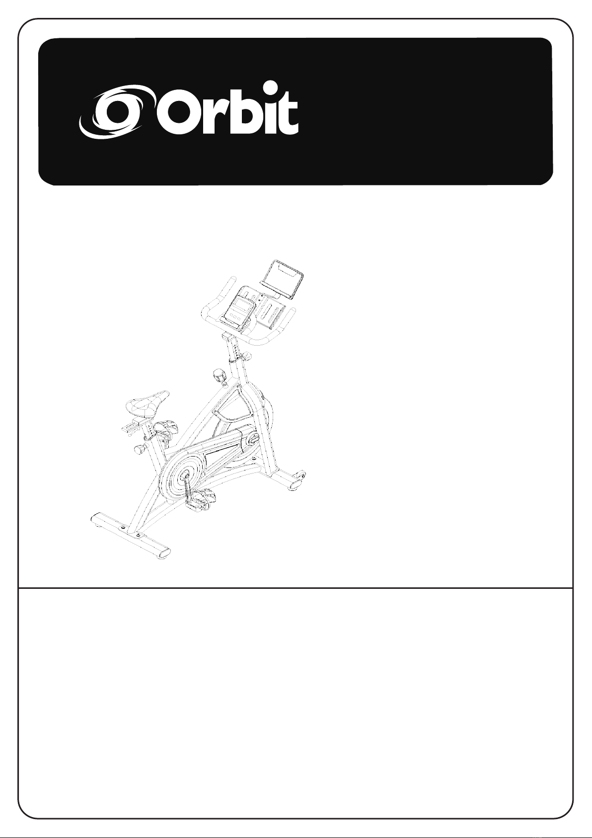
Orbit Apex II OSP610 User manual

OSP610
OSP610 Apex II Spin Bike
TOOLS REQUIRED
FOR ASSEMBLY:
- Adjustable Wrench
- Pliers
- Hammer
• Warranty
• Assembly
• Parts
240 lbs/110 kgs.
OSP610
OSP610
OSP610
Owner’s Manual OSP610
CAUTION:
1. Weight on this product should not exceed 240lbs / 110kgs.
2. Exercise of a strenuous nature, as is customarily done on this equipment, should not be
undertaken without first consulting a physician. No specific health claims are made or implied
as they relate to the equipment.
Measurements made by the equipment are believed to be accurate, but only the
measurements of your physician should be relied upon.
IMPORTANT: Read all instructions carefully before using this product. Retain this product
owner’s manual for future reference.

ASSEMBLY ADVICE
Dear Customer,
Congratulations on your purchase.
Please read this instruction manual very carefully before using this item.
You will nd important information regarding safety of your SPIN BIKE.
Note the following precautions before assembling or operating the machine.
ASSEMBLY ADVICE
Carefully read and understand the Assembly Instructions:
• Keep bystanders and children away from the product you are assembling at all
times.
• Do not connect power supply (if applicable) to the machine until instructed to do
so.
• Do not assemble this machine outdoors or in a wet or moist location.
• Ensure the seat, frame and pedals are xed as per instruction, are tight and
secured, and are regularly / periodically checked.
• Check all bolts and other connections before using the machine for the rst time
and ensure that they are in safe condition.
• Assemble the machine exactly as per the descriptions in the instruction manual.
• Some components of the machine can be heavy or awkward. Use a second
person when doing the assembly steps involving these parts. Do not do steps that
involve heavy lifting or awkward or twisting movements on your own.
• Set up this machine on a solid, level, horizontal surface.
• Do not try to change the design or functionality of this machine. This could
compromise the safety of this machine and will void the warranty.
• If replacement parts are necessary, use only genuine replacement parts and
hardware. Failure to use genuine replacement parts can cause a risk to users,
keep the machine from operating correctly and void the warranty.
• Do not use the machine until it has been fully assembled and inspected for correct
performance in accordance with the Manual.
( i )

WARNINGS
READ BEFORE USE
Before using this Equipment, Obey the following warnings:
• Keep children and pets away from the SPIN BIKE at all times Children should be supervised
to ensure that they do not play with the appliance.
DO NOT leave unattended children in the same room with the machine.
• This appliance is not intended for use by persons (including children) with reduced
physical, sensory or mental capabilities, or lack of experience and knowledge, unless given
supervision or instruction concerning use of the cycle by a person responsible for their safety.
• Before beginning training, remove all objects and obstacles within a radius of 2 meters from
the machine. DO NOT place any sharp objects around the SPIN BIKE.
• Position the SPIN BIKE on a clear, level surface away from water and moisture. Place mat
under the unit to help keep the machine stable and to protect the oor.
• Use the SPIN BIKE only for its intended use as described in this manual. DO NOT use any
other accessories not recommended by the manufacturer.
• Assemble the machine exactly as the descriptions in the Instruction Manual.
• Hold a routine inspection of the equipment. Pay special attention to components which are
the most susceptible to wear, i.e. connecting points and wheels. The defective components
should be replaced immediately. The safety level of this equipment can only be maintained
by doing so. Please don’t use the SPIN BIKE until it is repaired well.
• NEVER operate the SPIN BIKE if it is not functioning properly.
• This machine can be used for only one person’s training at a time.
• Do not use abrasive cleaning articles to clean the machine. Remove drops of sweat from the
machine immediately after nishing training.
• Always wear appropriate workout clothing when exercising. Running or aerobic shoes are
also required.
• Before exercising, always do stretching rst.
• The power of the machine increases when increasing the speed, and the reverse. The
machine is equipped with adjustable knob, which adjusts the resistance.
WARNING: BEFORE BEGINNING THIS OR ANY EXERCISE PROGRAM,
CONSULT YOUR PHYSICIAN FIRST.
( ii )

MAINTENANCE INSTRUCTIONS
Read all maintenance instructions fully before you start any repair work. In some
conditions, an assistant is required to do the necessary tasks.
Equipment must be regularly examined for damage and wear. The owner is
responsible to make sure that regular maintenance is done. Worn or damaged
components must be repaired or replaced immediately.
Only manufacturer supplied components can be used to maintain and repair the
equipment.
Disconnect all power (if applicable) to the machine before you do any work,
dissassembly or service.
Daily:
• Before each use, examine the exercise machine for loose, broken, damaged, or
worn parts. DO NOT use if found in this condition. Repair or replace all parts at the
rst sign of wear or damage.
• Make sure adjustment knobs are tight. Tighten as necessary. After each workout,
use a damp cloth to wipe your machine and Console free of moisture.
• Ensure seat is securely in correct place for your height.
• Ensure foot straps are set to correst position for your shoe before starting
exercise.
Note: If necessary, only use a mild detergent(dish soap) with a soft, lint free cloth
to clean the Console. DO NOT clean with a petroleum based solvent, automotive
cleaner, or any product that contains ammonia. DO NOT clean the Console in direct
sunlight or at high temperatures. Be sure to keep the Console free of moisture.
Weekly:
• Check pedals and tighten as necessary.
• Clean the machine to remove any dust, dirt, or grime from the surfaces.
• Check for smooth seat operation. If needed, sparingly apply a thin coating of
silicone lube to ease operation.
• Silicone lubricant is not intended for human consumption. Keep out of reach of
children. Store in a safe place.
Note: DO NOT use petroleum based products.
Monthly (or after 20 hours):
• Check Crank Arms and tighten as necessary. Make sure all bolts and screws are
tight. Tighten as necessary.
• Check the drive belt tension and adjust if necessary.
• Checking the Drive Belt Tension
• To check the Drive Belt tension, the bike needs to be operated. Get the pedals
rotating at about 20 RPM. Then suddenly increase the RPM to your maximum
ability. If the pedals move normally with no slipping, the tension is correct. If the
Pedals slip, the belt needs to be adjusted.
( iii )

MAINTENANCE INSTRUCTIONS
TROUBLESHOOTING
No Display / Partial Display / Unit will not Turn On:
• Check batteries in Console, replace if required, ensure connection to speed
sensor is good.
• Connection should be secure and undamaged. Replace adapter or connection at
unit if either are damaged.
• Check data cable integrity All wires in cable should be intact. If any are visibly
crimped or cut, replace cable.
• Check console display for damage
• Check for visual sign that console display is cracked or otherwise damaged.
Replace Console if damaged.
• Console Display If Console only has partial display and all connections are ne,
replace the Console.
• If the above steps do not resolve the problem, contact Customer Service or your
local distributor.
Speed Display is not Accurate:
• Check Speed Sensor.
• Check Magnet position.
• Speed Sensor Magnet should be in place on Flywheel.
Speed Displayed is Always “0” / Stuck in Pause mode:
• Check Data cable.
• Make sure the data cable is connected to the Console and the main frame
assembly.
• Check Speed Sensor.
• Make sure the RPM Sensor Magnet and the RPM Sensor are in place
No Speed / RPM Reading:
• Check data cable integrity. All wires in cable should be intact. If any are cut or
crimped, replace cable.
• Check data cable connections / orientation. Be sure cable is connected securely
and oriented properly.
• Small latch on connector should line up and snap into place.
• Check Speed Sensor Magnet Position. Speed Sensor Magnet should be in place
on Flywheel.
• Check Speed Sensor Assembly Speed Sensor Assembly should be aligned with
magnet and connected to data cable. Realign sensor if necessary. Replace if there
is any damage to the sensor or the connecting wire.
( iv )

MAINTENANCE INSTRUCTIONS
TROUBLESHOOTING CONTINUED
Unit Rocks / Does not Sit Level:
• Check level adjustment. Levellers may be turned to level machine.
• Check surface under unit. Adjustment may not be able to compensate for
extremely uneven surfaces.
• Move machine to level area.
Pedals Loose / Unit Difcult to Pedal / Pedals Seem to Skip or Slip with a
Sudden Increase in RPM:
• Check pedal to crank connection. Pedal should be tightened securely to Crank
Arm. Be sure connection is not cross-threaded.
• Check Crank arm to Axle connection. Crank arm should be tightened securely to
Axle.
Clicking sound when Pedalling:
• Check pedal to Crank connection.
• Remove Pedals. Make sure there is no debris on threads, and reinstall the Pedals.
Seat Post Movement:
• Check locking pin. Be sure Adjustment Pin is locked into one of the Seat Post
adjustment holes.
• Check locking Knob Be sure Knob is securely tightened.
MAINTENANCE
Maintenance Parts:
• Frame, Covers, Seat, Seat Post, Seat Slider, Crank Arms, Pedals (with Foot
Strap), Handlebar, Adjustment Handles, Belt(or Chain), Axle, Flywheel, Console,
Data Cable, Brake or Magnet. See Owners Manual for Part Names and Numbers.
Contact the Orbit Fitness Customer Service Department at:
Email: service@orbittness.com.au Phone: (08) 6241 3050
Address: 28 Fellowship Road Gnangara, Western Australia 6077
Website: www.orbittness.com.au
( v )

TABLE OF CONTENT
Safety Instructions ………………………………. 2
Before You Begin …………………………………..3
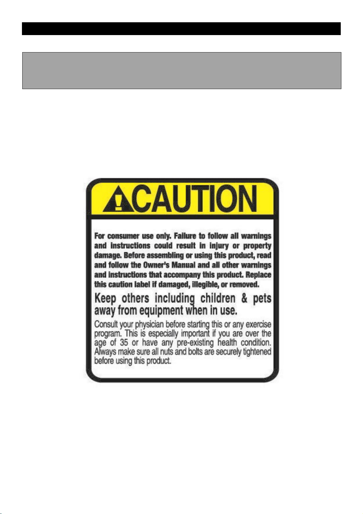
Equipment Warning, Warning Labels ..………… 4
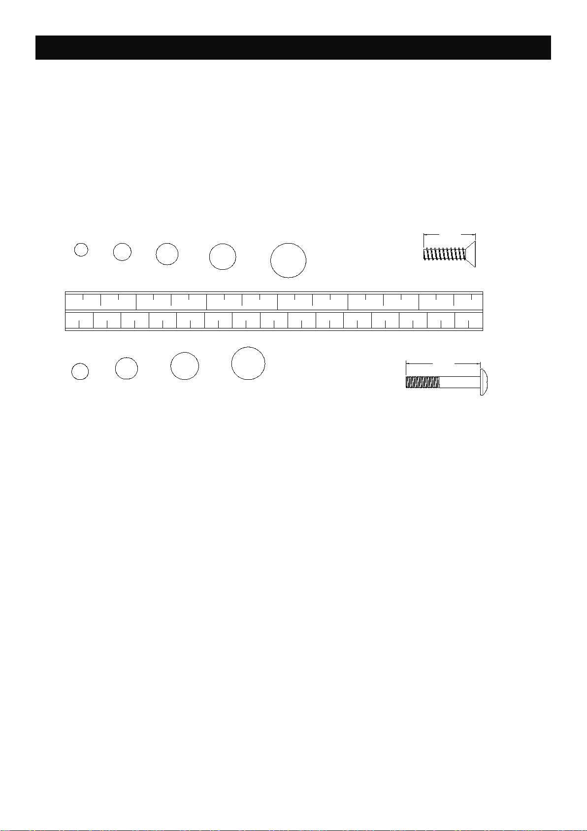
Hardware Identification Chart….……..…….. 5 - 6
General Introduction & Warm Up...……..…..….. 7
Assembly Instructions.……………..……….8-10
Beginner’s Guide …………………………………11
Transportation Instructions…………………… 12
Computer Instructions..………………....……13-15
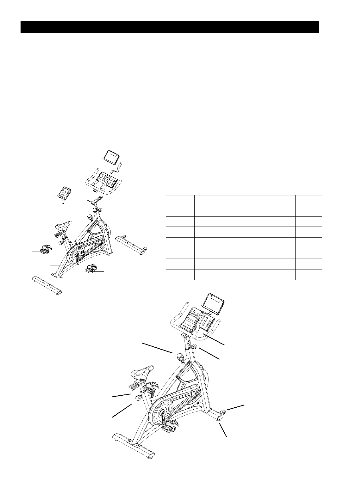
Product Parts Drawing……………..……………16
Parts List…….………………….……………. 17 - 19
SAFETY INSTRUCTIONS
1.
To reduce the risk of serious injury, read the following Safety Instructions before using the SPIN BIKE.
2.
Save these instructions and ensure that other exercisers read this manual prior to using the SPIN
BIKE for the first time.
3.
Read all warnings and cautions posted on the SPIN BIKE.
4.
The SPIN BIKE should only be used after a thorough review of the Owner’s Manual. Make sure that
it is properly assembled and tightened before use.
5.
We recommend that two people be available for assembly of this product.
6.
Keep children away from the SPIN BIKE. Do not allow children to use or play on the SPIN BIKE.
Keep children and pets away from the SPIN BIKE when it is in use.
7.
It is recommended that you place this exercise equipment on an equipment mat.
8.
Set up and operate the SPIN BIKE on a solid level surface. Do not position the SPIN BIKE on
loose rugs or uneven surfaces.
9.
Make sure that adequate space is available for access to and around the SPIN BIKE.
10.
Before using, inspect the SPIN BIKE for worn or loose components, and securely tighten or replace
any worn or loose components prior to use.
11.
Consult a physician prior to commencing an exercise program and follow his/her recommendations
in developing your fitness program. If at any time during exercise you feel faint, dizzy, or
experience pain, stop and consult your physician. Failure to follow all warnings and instructions
could result in serious injury or death.
12.
Always choose the workout which best fits your physical strength and flexibility level. Know your limits
and train within them. Always use common sense when exercising.
13.
Do not wear loose or dangling clothing while using the SPIN BIKE.
14.
Never exercise in bare feet or socks; always wear proper footwear such as running, walking, or cross
training shoes that fit well, provide foot support, and feature non-skid rubber soles.
15.
Be careful to maintain your balance while using, mounting, dismounting, or assembling the SPIN
BIKE, loss of balance may result in a fall and bodily injury.
16.
The SPIN BIKE should not be used by persons weighing over 242lbs /110kgs.
17.
The SPIN BIKE should be used by only one person at a time.
2

3
NO.
DESCRIPTION
QTY
1
Main Frame
1
2
Rear Stabilizer Tube
1
3
Front Stabilizer Tube
1
8
Handlebar
1
16L/R
Pedal (Left/ Right)
2
17
Tablet Holder Support Tube
1
40
Tablet Holder
1
BEFORE YOU BEGIN
Thank you for choosing the SPIN BIKE. We take
great pride in producing this quality product and
hope it will provide many hours of quality exercise
to make you feel better, look better, and enjoy life to
its fullest.
It's a fact that a regular exercise program can
improve your physical and mental health. Too often,
our busy lifestyles limit our time and opportunity to
exercise.
The SPIN BIKE provides a convenient and simple
method to begin your journey of getting your body
in shape and achieving a happier and healthier
lifestyle.
Before reading further, please review the drawing
below and familiarize yourself with the parts that
are labeled. Read this manual carefully before
using the SPIN BIKE.
52
17
8
40
3
16L
1
16R
2
Brake Knob
Adjustment Knob
L-Shaped Knob
Adjustment Knob
Transport Wheel
L-Shaped Knob
Feet Pad

4
EQUIPMENT WARNING, WARNING LABELS
This chart is provided to help identify the warning, caution and notice labels on the SPIN
BIKE. Please take a moment to familiarize yourself with all of the warning, caution and
notice labels.
WARNING LABEL
Label is larger than actual

01/2 11/2 21/2 1/2 1/2 1/2
345
010 20 30 40 50 60 70 80 90 100 110 120 130 140 150
in.
mm.
6810 12
3/16" 1/4" 5/16" 3/8" 1/2"
INCHES
length
MILLIMETERS
length
This chart is provided to help identify the hardware used in the assembly process. Place the
washers or the ends of the bolts or screws on the circles to check for the correct diameter. Use the
small scale to check the length of the bolts and screws.
NOTICE:The length of all bolts and screws, except those with flat
heads, is measured from below the head to the end of
the bolt or screw. Flat head bolts and screws are
measured from the top of the head to the end of the bolt
HARDWARE IDENTIFICATION CHART
5

6
After unpacking the unit, open the hardware bag and make sure that you have all of
the following fasteners. Some fasteners may be already attached to the parts.
Picture
Part No.
Description
Qty
21
L-Shaped Knob M10x25
1
66
Button Head Cap Screw M8x50
4
72
Button Head Cap Screw M5x12
2
69
Self-Tapping Screw ST4x6
2
85
Flat Washer φ10.5x20x2
4
84
Stainless Steel Flat
Washer φ10.5x20x2
1
79
Flat Washer φ5.5x12x1
2
87
Flat Washer φ4.5x12x1
2
91
Allen Wrench S3
1
92
Allen Wrench S6
1
90
Open End Wrench S13-15-17
1

7
GENERAL INTRODUCTION
GENERAL INTRODUCTION & WARM UP
BEFORE EXERCISING ON THE SPIN BIKE, PLEASE READ THIS INSTRUCTION
MANUAL CAREFULLY. CONSULT YOUR PHYSICIAN FOR ADDITIONAL HELP,
ESPECIALLY FOR THOSE WHOSE AGE OVER 30 OR WHO HAVE KNOWN HEALTH
PROBLEMS. MAKE SURE TO WARN UP THOROUGHLY AND FOLLOW THE
BEGINNER’S GUIDE TO START THE OPERATION ON THE SPIN BIKE.
A Spin Bike can help burn a huge amount of
calories within a relatively short period of time.
It is also a great way of working out that trains your
endurance and cardio at the same time. Please
read through the manual instructions and follow
step by step to understand how the Spin Bike can
help you bring the maximum value.
WARM UP
It is recommended to have at least 10 – 15 minutes
of warm up before you starting pedaling. It allows
you to exercise more effectively and prevent injury
from intensive workouts. Please consider the
following steps to begin your warm-up period:
1. Cross-Body Shoulder Stretch
2. Cow Face Pose
3. Standing Quad Stretch
4. Hip Flexor Stretch

8
ASSEMBLY INSTRUCTIONS
STEP 1
Attach Front Stabilizer Tube (3) and Rear Stabilizer Tube (2) to Main Frame (1) by using: 4pcs
of Button Head Cap Screw M10x50 (66) and 4pcs of Flat Washer φ10.5x20x2.0 (85).
NOTE: Fully tighten screws at the end of this step.
66
85
3
66
85
1
2
STEP 2
Attach Handlebar (8) to Upright Post Tube (6) by using: 1pc of L-Shaped Knob (21), and 1 pc of
Stainless Steel Flat Washer φ10.5x20x2.0(84). NOTE: Fully tighten screws at end of this step.
8
7
84
6 21
STEP 3
Attach Tablet Holder Support Tube (17) onto Handlebar (8) by using: 2 pcs of Button Head
Cap Screw M8x12 (72), and 2 pcs of Flat Washer φ5.5x12x1(79). Then attach Tablet Holder
(52)

9
onto Tablet Holder Support Tube (17) by using: 2 pcs of Self-Tapping Screw ST4x6 (69), and 2
pcs of Flat Washer φ4.5x12x1(87).
NOTE: Fully tighten screws at end of this step.
52 17
72 87
79 69
8
STEP 4
Attach Left/ Right Pedals (16L/R) to Left / Right Cranks (19 & 20), and tighten them by using:
Open End Wrench (90).
19
16L
20
16R
STEP 5
Remove 4 pcs of Phillips Truss Head Screw M5x10 (41) from Monitor (40), and then attach
Monitor (40) onto the steel plate of Handlebar (8) by using the same 4 pcs of Phillips Truss

10
Head Screw M5x10 (41).
Then connect Sensor Wire (38) with Monitor Wire (40a).
NOTE: Fully tighten screws at end of this step.
40
40a
38
41
40a

BEGINNER’S GUIDE
OPERATION INSTRUCTIONS
SEAT POSITION ADJUSTMENT
To adjust the seat height, loosen Post Knob (18) and slide Seat Post Tube (4) up or down to the
appropriate height position, and then tighten the Post Knob (18). To adjust the seat forward/ backward,
loosen L-Shaped Knob (21) and slide Horizontal Seat Post Tube (5) front or back to the appropriate
position, and then tighten the L-Shaped Knob (21).
UPRIGHT POST POSITION ADJUSTMENT
To adjust the upright post height, loosen Post Knob (18) and slide Upright Post Tube (6) up or down to the
appropriate height position, and then tighten the Post Knob (18). To adjust the handlebar forward/
backward, loosen L-Shaped Knob (21) and slide Handlebar Adjustment Plate (7) front or back to the
appropriate position, and then tighten the L-Shaped Knob (21).
FEET PAD HEIGHT ADJUSTMENT
To make sure the stability and safety of the SPIN BIKE, adjust the Feet Pads (15) underneath the Front /
Rear Stabilizer Tubes (2 & 3) by rotating the Feet Pads (15) for a few turns when you feel the SPIN BIKE
shakes during your riding.
RESISTANCE ADJUSTMENT
To adjust the resistance, rotate Brake Knob (22) to the right to increase the resistance; rotate Brake
Knob (22) to the left to decrease the resistance.
11

BEGINNER’S GUIDE
TRANSPORTATION INSTRUCTIONS
8
49 7 21
5 4 6 +
21 22
18
一
18
15
B A
Before moving the SPIN BIKE, make sure the Handlebar (8) is tightened.
Stand in front of the SPIN BIKE as illustrated below, and hold the Handlebar (8) to tilt the SPIN BIKE toward you
until the Transport Wheels (3) touch the ground or floor. Move forward / backward of the SPIN BIKE to the place
you like to storage or exercise.
8
21
18
3
12

13
COMPUTER INSTRUCTIONS
I.
BASIC FUNCTIONS
POWER ON:
- Start riding the SPIN BIKE to turn on the monitor, or press any button to activate the monitor.
POWER OFF:
- When there is no activity more than 4 minutes, the monitor will automatically enter sleep mode. You can
press any buttons to reactivate the monitor and resume the exercise and the previous training data.

14
BATTERY:
- Size of battery is AAA type and the monitor requires 2 x AAA batteries.
SET (button):
- Under countdown programs, press this button to increase / decrease the target value setting. Hold this
button to automatically increase the data value faster.
MODE (button):
- Press this button to choose different data displayed on the monitor screen.
- Press and hold this button for over 2 seconds to reset all the training data to 0.
RESET (button):
- Press and hold this button for over 2 seconds to reset all the training data to 0.
II.
CONSOLE DISPLAY
SCAN:
- Show all data displays in below sequence: TIME→SPD (SPEED)→DIST (DISTANCE)→ODO (ODOMETER)→CAL
(CALORIES)→ PULSE→TCNT (TOTAL COUNT)
TIME:
- Workout time is accumulated under manual workout mode.
- Display range: 00:00 ~ 99:59 MINUTES : SECONDS.
- Under Time Countdown Program, target time can be adjusted and the setting range is 00:00 ~ 99:00
MINUTES : SECONDS.
SPEED:
- Display the current exercising speed during the exercise.
- Unit of speed is displayed in mile / minute or kilometer / minute.
DISTANCE:
- Display the total distance accumulated during the workout.
- Unit displayed in mile or kilometer.
- Display range: 0 ~ 99.99 miles or milometers.

15
ODO:
- Show the total accumulated distance from previous workouts.
CALORIES:
- Display the total calories burned during the workout.
- Display range: 0 ~ 9999 calories.
PULSE:
- Display the heart rate at any moment during the exercise. To use this function, the user must wear Heart Rate
Chest Strap.
- Display range: 0 ~ 230 beats per minute.
III.
COUNTDOWN PROGRAMS
The Monitor has 4 countdown programs: Time Countdown, Distance Countdown, Calories Countdown, and
Pulse Countdown.
TIME COUNTDOWN:
- To enter the Time Countdown Program, press “MODE” button to show the default TIME value. To adjust the
target time, press “SET” button to increase the value, and then press “MODE” button again to confirm the
value setting.
- The setting range is 00:00 ~ 99:00 MINUTES : SECONDS.
DISTANCE COUNTDOWN:
- To enter the Distance Countdown Program, press “MODE” button to show the default DISTANCE value. To
adjust the target distance, press “SET” button to increase the value, and then press “MODE” button again to
confirm the value setting.
- The setting range is 0 ~ 99.50 miles or kilometers.
CALORIES COUNTDOWN:
- To enter the Calories Countdown Program, press “MODE” button to show the default CALORIES value. To
adjust the target calories, press “SET” button to increase the value, and then press “MODE” button again to
confirm the value setting.
- The setting range is 0 ~ 9990 calories.
Table of contents
Other Orbit Fitness Equipment manuals

Orbit
Orbit VM120 User manual

Orbit
Orbit OBE8731B User manual

Orbit
Orbit OBE165AF User manual

Orbit
Orbit OBS 2233B User manual

Orbit
Orbit OBA2123A User manual

Orbit
Orbit MAX5 User manual

Orbit
Orbit OBB007 User manual

Orbit
Orbit Ergo 6.0 User manual

Orbit
Orbit ERGO6.2 User manual

Orbit
Orbit OBB007-LAT User manual