manuals.online logo
Brands
  1. Home
  2. •
  3. Brands
  4. •
  5. Oriental motor
  6. •
  7. Engine
  8. •
  9. Oriental motor 0GN KA Series User manual

Oriental motor 0GN KA Series User manual

HG-9025-2
OPERATING MANUAL
Gearhead
(GN・GE・GU Types)
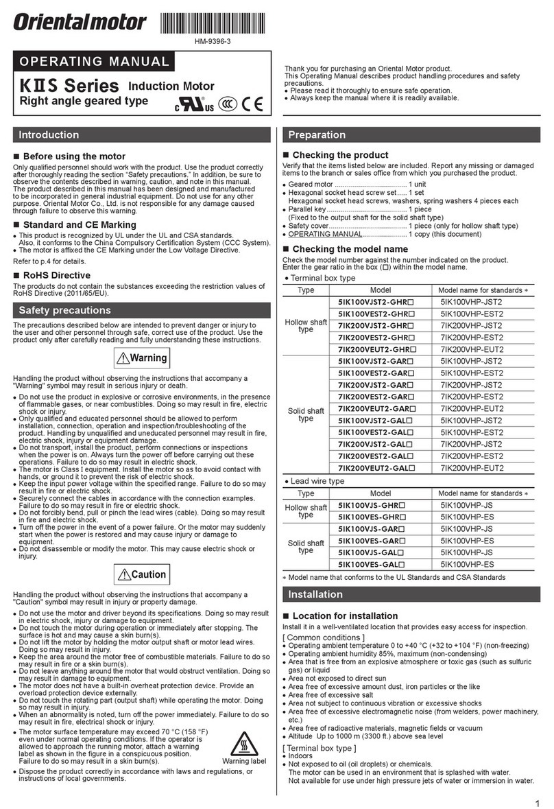
Thank you for purchasing an Oriental Motor product.
To ensure correct operation, please read this manual carefully
before using your gearhead.
Introduction

Before using the gearhead
Only qualified personnel should work with the product. To ensure correct
operation, please read this manual carefully before using your gearhead.
Should you require the inspection or repair of internal parts, contact the Oriental
Motor office where you purchased the product.

Hazardous substances
RoHS (Directive 2002/95/EC 27Jan.2003) Compliant
Verifying the product name and accessories
Check the model names of the motor and gearhead. Gearheads and motors will fit
together only if they are both of the same frame size (first digit of model name is
the same) and of the same gear type (GN, GE appear in both the gearhead and
motor model name).
<Example> 4 IK25 GN -AW2 4 GN 25SA
Frame size
Gear type series
䊶Motor model name 䊶Gearhead model name
Gearhead comes with following accessories for mounting the motor and gearhead
on equipment. Also check them completely provided.
Accessories
• Screws for mounting, Hexagon nuts, Washers 4 pcs. each
• Key 1 pc.
(Key is not provided with gearheads that have a flat on the output shaft.)
Key and key slot dimensions (Unit = in.)
GE, GU Type
1.125±0.0079 0.1875+0.0016
0
0.1875 0
-
0.0012
0.1875 0
-
0.0012
0.108+0.0039
0
Table 1. Size of screws for mounting
Size of screw for mounting (provided)
Gearhead
model name Thread series × Length
(in.) Type
0GN3KA to 180KA No.4-40UNC × 1.57
2GN3SA to 18SA No.8-32UNC × 1.97
2GN25SA to 180SA No.8-32UNC × 2.36
3GN3SA to 18SA No.10-24UNC × 1.97
3GN25SA to 180SA No.10-24UNC × 2.56
4GN3SA to 18SA No.10-24UNC × 1.97
4GN25SA to 180SA No.10-24UNC × 2.56
5GN3SA to 18SA 1/4-20UNC × 2.75
5GN25SA to 180SA 1/4-20UNC × 3.25
Cross-recessed
head machine
screw
5GE3SA to 180SA
5GU3KA to 180KA 1/4-20UNC × 3.75 Hexagon socket
head screw
Table 2. Installation hole dimensions
Installation hole dimensions (in.)Gearhead
model name ØA ØB C 4רD
0GNKA 1.89 0.71 0.32 0.14
2GNSA 2.76 0.94 0.39 0.18
3GNSA 3.23 1.18 0.59 0.22
4GNSA 3.70 1.34 0.59 0.22
5GNSA 4.09 1.42 0.71 0.27
5GESA
5GUKA 4.09 1.34 0.71 0.27
∗ The square box in the gearhead model will contain a value representing the
gear ratio.
∗ ØB indicates the external dimension
of the product.
Provide a hole with a diameter of
"ØB +0.04 in. or more."
< Installation holes >
ØB
ØA
4רD
C
Assembly
Align the gearhead and motor as in the Figure below, then engage the pinion
section of the shaft to the gear gently by turning the gearhead slightly in both
directions until the gearhead and motor fit flush together.
Note Forcing the motor and gearhead together during assemble
or permitting contamination by foreign matter inside the
gearhead will cause excess noise and/or shorter life of the
gearhead.
Output shaft of moto
r
Gearhead
Pilot section
Motor
Flange
Mating surface
Installing gearmotor
Motor
Gearhead
Screws for mounting
provided with gearhead
Mounting
Plate
Washers
Nuts
Use the mounting screws provided with the gearhead to mount the gearhead and
motor on equipment.
• Decimal gearhead
Motor
Decimal gearhead
Gearhead
Washers
Nuts
Screws for mounting
provided with decimal gearhead
Mounting
Plate
Use the screws provided with the decimal gearhead and secure all parts so that
there are no gaps between the motor flange face and the recessed area of the
decimal gearhead and between the decimal gearhead and the gearhead's recessed
area.
∗ Dedicated mounting brackets can also be used for installing gearmotor.
For details, please refer to catalogue.
∗ Refer Table 2 for the size of installation hole.
Attaching load
The shaft of the gearhead has been machined to an outer diameter tolerance of h7
and is provided with a key slot for connecting the transmission parts. (Model 0GN
to 5GN type have a flat on the shaft.)
When connecting the transmission parts, ensure that the shaft and parts have a
clearance fit, and secure with a screw to prevent the parts from wobbling.
Use a screw hole (No.10-24UNC, effective depth 0.39 in.) provided at the tip of
the output shaft of 5GESA as an auxiliary means for preventing the transfer
mechanism from disengaging.
< The example of output axis
tip screw hole use >
Motor Gearhead
Key
Fixed screw
Transmission parts
Fixed screw
Screw
Spacer
Transmission parts
Note Do not use excessive force, or hammer the
transmission parts onto the gearmotor shaft
as damage may occur.
Precautions for operation
• Use your gearmotor under ambient temperature of +14 to +122 °F and 85%
humidity.
• Do not use your gearmotor where it may be exposed direct sunlight water
and/or oil.
• Do not use your gearmotor in locations subject to severe vibration or shock, a
large amount of dust, inflammable gas and or corrosive gas.
• On rare occasions, a small amount of grease may ooze out from the gearhead. If
there is concern over possible environmental damage resulting from the leakage of
grease, check for grease stains during regular inspections. Alternatively, install an
oil pan or other device to prevent leakage from causing further damage. Oil
leakage may lead to problems in the customer’s equipment or products.
• Direction of rotation of the gearhead output shaft
With some gear ratios, the motor and gearhead output shaft will rotates in opposite
directions. The direction of rotation does not change if a decimal gearhead is
connected.
Gear ratio
Gearhead model name Same direction as motor Opposite direction
to motor
3to 182GNSA 3GNSA
4GNSA 5GNSA 50 to 180 25 to 36
3to 912.5 to 180GNKA 5GESA
5GUKA 25 to 60 75 to 180
∗ The square box in the gearhead model will contain a value representing the
gear ratio.
• Maximum permissible torque
Since the output torque of the gearhead increases proportionally with the reduction
of speed, a high reduction ratio of the gearhead will result in an output torque that
cannot be taken up by the physical construction of the gearhead. Use gearheads
within the maximum permissible torque set for each speed reduction ratio. For the
values of the maximum permissible torque, please refer to catalogue. Also, be sure
shaft rotation is not stopped by an external force or load obstruction. The resulting
shock may damage the gearhead.
• Permissible overhung load and permissible thrust load
“Overhung load” refers to load placed on the output
shaft of the gearhead in a direction perpendicular to
the shaft as shown to the right. The “Thrust load” is a
load applied in the axial direction of the output shaft.
Since the overhung load and thrust load have a great
influence on the life of the bearings and strength of the
shaft, be careful not to exceed the maximum values
shown in the Table 3.
Gearhead
Overhung load
Thrust load
Table 3. Permissible overhung load and permissible thrust load
Permissible
overhung load (lb.)
Output axis tip
Gearhead
model
name
Gear
ratio
Maximum
permissible
torque
(lb-in) 0.39 in. 0.79 in.
Permissible
thrust load
(lb.)
0GNKA 3 to 180 8.8 4.5
-
3.3
3to 18 11.2 18
2GNSA 25 to 180 26 27 40 6.7
3to 18 18 27
3GNSA 25 to 180 44 33 56 9
3to 18 22 33
4GNSA 25 to 180 70 45 67 11.2
3to 18 56 78
5GNSA 25 to 180 88 67 101 22
3to 990 112
12.5 to 18 101 135
5GESA
5GUKA 25 to 180
177
112 157
33
∗ The square box in the gearhead model will contain a value representing the
gear ratio.
• Unauthorized reproduction or copying of all or part of this Operating Manual
is prohibited.
• Oriental Motor shall not be liable whatsoever for any patent-related problem
arising in connection with the use of any information, circuit, equipment or
device described in the manual.
• Characteristics, specifications and dimensions are subject to change without
notice.
• While we make every effort to offer accurate information in the manual, we
welcome your input. Should you find unclear descriptions, errors or
omissions, please contact the nearest office.
• is a trademark of Oriental Motor Co., Ltd.
© Copyright ORIENTAL MOTOR CO., LTD. 2006
• Please contact your nearest Oriental Motor office for further information.
ORIENTAL MOTOR U.S.A. CORP.
Technical Support Line Tel:(800)468-3982
A
vailable from 7:30 AM to 5:00 PM, P.S.T.
E-mail: techsupport@orientalmotor.com
www.orientalmotor.com
ORIENTAL MOTOR CO., LTD.
Headquarters Tokyo, Japan
Tel:(03)3835-0684 Fax:(03)3835-1890 Printed on Recycled Pape
r

This manual suits for next models

6

Other Oriental motor Engine manuals

Oriental motor World K Series User manual

Oriental motor

Oriental motor World K Series User manual

Oriental motor SMK Series User manual

Oriental motor

Oriental motor SMK Series User manual

Oriental motor BMU Series User manual

Oriental motor

Oriental motor BMU Series User manual

Oriental motor World K Series User manual

Oriental motor

Oriental motor World K Series User manual

Oriental motor BMU Series User manual

Oriental motor

Oriental motor BMU Series User manual

Oriental motor BH Series User manual

Oriental motor

Oriental motor BH Series User manual

Oriental motor PKP56 Series User manual

Oriental motor

Oriental motor PKP56 Series User manual

Oriental motor K Series User manual

Oriental motor

Oriental motor K Series User manual

Oriental motor SPR II Series User manual

Oriental motor

Oriental motor SPR II Series User manual

Oriental motor BLV Series User manual

Oriental motor

Oriental motor BLV Series User manual

Oriental motor PKP Series User manual

Oriental motor

Oriental motor PKP Series User manual

Oriental motor K Series User manual

Oriental motor

Oriental motor K Series User manual

Oriental motor K Series User manual

Oriental motor

Oriental motor K Series User manual

Oriental motor DGII Series User manual

Oriental motor

Oriental motor DGII Series User manual

Oriental motor PK Series User manual

Oriental motor

Oriental motor PK Series User manual

Oriental motor CVD Series User manual

Oriental motor

Oriental motor CVD Series User manual

Oriental motor PKP Series User manual

Oriental motor

Oriental motor PKP Series User manual

Oriental motor BLE2 Series User manual

Oriental motor

Oriental motor BLE2 Series User manual

Oriental motor BLV Series User manual

Oriental motor

Oriental motor BLV Series User manual

Oriental motor BMU Series User manual

Oriental motor

Oriental motor BMU Series User manual

Oriental motor World K Series User manual

Oriental motor

Oriental motor World K Series User manual

Oriental motor AZM14 User manual

Oriental motor

Oriental motor AZM14 User manual

Oriental motor Alpha Step AZ Series User manual

Oriental motor

Oriental motor Alpha Step AZ Series User manual

Oriental motor K Series User manual

Oriental motor

Oriental motor K Series User manual

Popular Engine manuals by other brands

Volvo Penta D25A MS Operator's manual

Volvo Penta

Volvo Penta D25A MS Operator's manual

YS 140LIMITED Operator's manual

YS

YS 140LIMITED Operator's manual

Denison Hydraulics Goldcup Series Installation & Overhaul Instructions

Denison Hydraulics

Denison Hydraulics Goldcup Series Installation & Overhaul Instructions

MTD P71 Series Shop Manual

MTD

MTD P71 Series Shop Manual

BMW M57 Service training

BMW

BMW M57 Service training

Perkins UA manual

Perkins

Perkins UA manual

ScubaJet SJ 2 user manual

ScubaJet

ScubaJet SJ 2 user manual

Chamberlain LM-1600 installation manual

Chamberlain

Chamberlain LM-1600 installation manual

MerCruiser 305 CID (5.0L) Service manual

MerCruiser

MerCruiser 305 CID (5.0L) Service manual

YARDMAX YT5565 Operator's manual

YARDMAX

YARDMAX YT5565 Operator's manual

MASSEY FERGUSON AGCO SISU POWER - brochure

MASSEY FERGUSON

MASSEY FERGUSON AGCO SISU POWER - brochure

3B SCIENTIFIC PHYSICS 1021806 instruction sheet

3B SCIENTIFIC PHYSICS

3B SCIENTIFIC PHYSICS 1021806 instruction sheet

Moons' Applied Motion Products SSM23Q/IP Hardware manual

Moons'

Moons' Applied Motion Products SSM23Q/IP Hardware manual

SOMFY GOME MOTION Roll Up 28 WT instructions

SOMFY

SOMFY GOME MOTION Roll Up 28 WT instructions

Oemer QL Installation, use and maintenance manual

Oemer

Oemer QL Installation, use and maintenance manual

Yanmar 2TNV70-HGE General specification

Yanmar

Yanmar 2TNV70-HGE General specification

Mitsubishi 4G1 series General information

Mitsubishi

Mitsubishi 4G1 series General information

MPI Himax HA2015 Series manual

MPI

MPI Himax HA2015 Series manual

manuals.online logo
manuals.online logoBrands
  • About & Mission
  • Contact us
  • Privacy Policy
  • Terms and Conditions

Copyright 2025 Manuals.Online. All Rights Reserved.