manuals.online logo
Brands
  1. Home
  2. •
  3. Brands
  4. •
  5. ORiNG
  6. •
  7. Network Router
  8. •
  9. ORiNG TGRST120-M12X-BP2-WV User manual

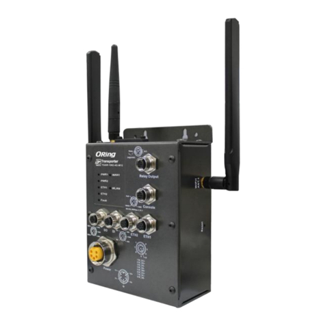
ORiNG TGRST120-M12X-BP2-WV User manual

3A@2 4VDC
Rela y N.C.
Rel ay Outp ut
Con so le
RSVD
RXD
RS-2 32, 1152 00bps , 8, N, 1
GND
TXD
N.C.
G1
G2
G3
G4
G9
G10
G11
G12
G5
G6
G7
G8
G1~ G1 2
1 BI_D A+
2 BI_D A-
3 BI_D B+
4 BI_D B-
5 BI_D D+
6 BI_D D-
7 BI_D C-
8 BI_D C+
6
5
7
3
2
18
4
Pow er
24- 110 VDC
V-
N.C.
V+
N.C.
Powe r
Fail ure
Bypa ss
Powe r
Fail ure
Bypa ss
TGRS -T1 20-M 12X -BP2 -WV
LNK/ACT
Speed
Reset
G1
G2
G3
G4
G5
G6
G7
G8
G9
G10
G11
G12
LNK/ACT
Speed
PWR Stat us R. M. Ring Fault
Quick Installation Guide
Version 1.0
Quick Installation Guide
Introduction
PRINTED ON RECYCLED PAPER
Q I G
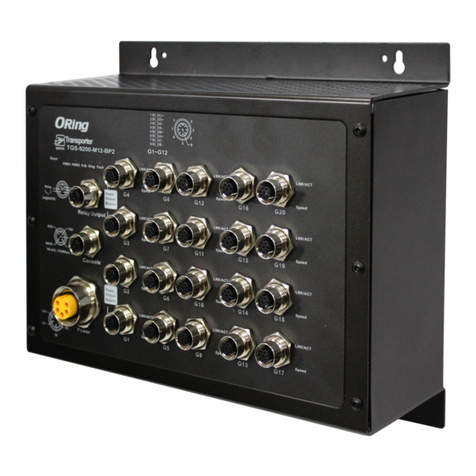
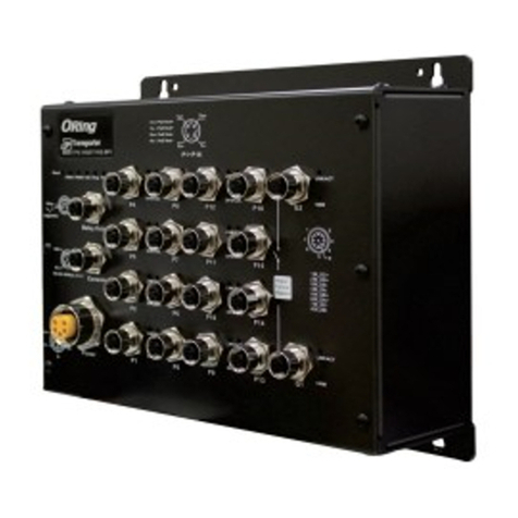
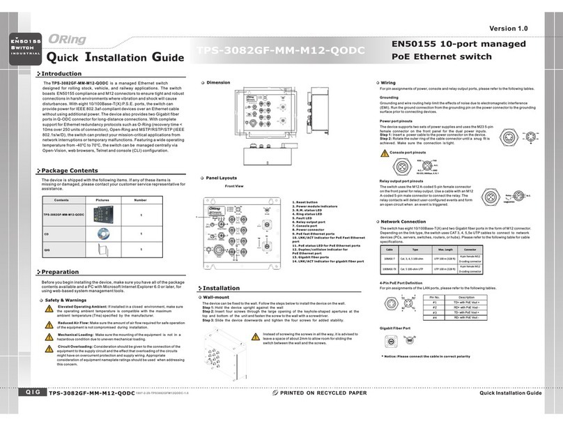
ORing's Transporter series managed Router switches are designed for
TM
industrial applications such as rolling stock, vehicle, and railway. The TGRS-
T120-M12X-BP2-WV, which is compliant with the EN50155 standard, is a
m a n a g e d G i g a b i t R e d u n d a n t R i n g E t h e r n e t s w i t c h w i t h
12x10/100/1000Base-T(X) ports which is specifically designed for the
toughest and fully compliant with EN50155 requirement. The switch support
IEC 61375-2-5 TTDP IEC 61375-2-3(Train Topology Discovery Protocol) and
TRDP (Train Real-Time Data Protocol) for railway application, improving the
operational efficiency and minimize configuration errors. It is specifically
designed for the toughest industrial environments. TGRS-T120-M12X-BP2-
WV EN50155 Ethernet switch uses M12 connectors to ensure tight, robust
connections, and guarantee reliable operation against environmental
disturbances, such as vibration and shock. TGRS-T120-M12X-BP2-WV
EN50155 provides a wide power input range from 24 to 110VDC. TGRS-T120-
M12X-BP2-WV includes 2 sets of bypass ports that protect the network from
failures and Network maintenance by ensuring network integrity during power
loss. And support wide operating temperature from -25 C to 70 C.
o o TGRS-
T120-M12X-BP2-WV can also be managed centralized and convenient by
Open-Vision, as well as the Web-based interface, Telnet and console (CLI)
configuration. Therefore, the router switch is one of the most reliable choice
for highly-managed and railway application.
Package Contents
Installation
Wall-mount
The device can be fixed to the wall. Follow the steps below to install the device on the wall.
Step 1: Hold the evice upright against the walld
Step 2: Insert four screws through the large opening of the keyhole-shaped apertures at the
top and bottom of the unit and fasten the screws to the wall with a screwdriver.
Step 3: Slide the evice downwards and tighten the four screws for added stability.d
The device is shipped with the following items. If any of these items is
missing or damaged, please contact your customer service representative
for assistance.
Preparation
Before you begin installing the device, make sure you have all of the package
contents available and a PC with Microsoft Internet Explorer 6.0 or later, for
using web-based system management tools.
Elevated Operating Ambient: If installed in a closed environment, make sure
the operating ambient temperature is compatible with the maximum
ambient temperature (Tma) specified by the manufacturer.
Reduced Air Flow: Make sure the amount of air flow required for safe operation
of the equipment is not compromised during installation.
Mechanical Loading: Make sure the mounting of the equipment is not in a
hazardous condition due to uneven mechanical loading.
Circuit Overloading: Consideration should be given to the connection of the
equipment to the supply circuit and the effect that overloading of the circuits
might have on overcurrent protection and supply wiring. Appropriate
consideration of equipment nameplate ratings should be used when addressing
this concern.
Safety & Warnings
For pin assignments of power, console and relay output ports, please refer to the following tables.
Contents
TGRS-T120-M12X-BP2-WV
Pictures Number
1
Panel Layouts
Front View
1. Power status LED
2. System status LED
3. R.M. status LED
4. Ring status LED
5. Fault LED
6. Reset button
7. Ethernet LAN ports
8. Ethernet WAN ports with bypass
9. Link/ACT LED for Gigabit ports
10. Speed LED for Gigabit ports
11. Console port
12. Relay output
13. Power connector
Wiring
Grounding
Grounding and wire routing help limit the effects of noise due to electromagnetic interference
(EMI). Run the ground connection from the grounding pin on the power connector to the grounding
surface prior to connecting devices.
Power port pinouts
The device supports one set of power supply and uses the M12 A-coded
5-pin male connector on the front panel for power input.
Step 1: Insert a power cable to the power connector on the device.
Step 2: Rotate the outer ring of the cable connector until a snug fit is
achieved. Make sure the connection is tight.
Relay output port pinouts
Relay N .C.
3A@24 VDC
Network Connection
The switch has twenty 10/100/1000Base-T(X) Ethernet ports in the form of M12 connector.
Depending on the link type, the switch uses CAT 3, 4, 5,5e UTP cables to connect to network
devices (PCs, servers, switches, routers, or hubs). Please refer to the following table for cable
specifications.
TGRS-T120-M12X-BP2-WV 1907-200-XX
S w i tc h
E N 5 0 1 5 5
I N D U S T R I A L
1
Instead of screwing the screws in all the way, it is advised to
leave a space of about 2mm to allow room for sliding the
switch between the wall and the screws.
Cable
Type
Max. Length
Connector
10BASE-T Cat. 3, 4, 5 100-ohm UTP 100 m (328 ft)
8-pin female M12
X-coding connector
100BASE-TX Cat. 5 100-ohm UTP UTP 100 m (328 ft)
8-pin female M12
X-coding connector
1000BASE-T Cat. 5/Cat. 5e 100-ohm UTP UTP 100 m (328 ft)
8-pin female M12
X-coding connector
For pin assignments of the Ethernet ports, please refer to the following tables.
QIG 1
11
12
13
4 5
6
2 3
The switch uses the M12 A-coded 5-pin female connector
on the front panel for relay output. Use a cable with an M12
A-coded 5-pin male connector to connect the relay. The
relay contacts will detect user-configured events and form
an close circuit when an event is triggered.
Console port pinouts
N.C.
RXD
RS-232, 115200bps, 8, N, 1
GND
TXD
N.C.
Dimension Unit =mm (Tolerance ±0.5mm)
TGRS-T120-M12X-BP2-WV EN50155 managed router switch
3A@24 VDC
Relay N.C.
Rel ay Outp ut
Con sol e
RSVD
RXD
RS-23 2, 11520 0bps, 8 , N, 1
GND
TXD
N.C.
G1
G2
G3
G4
G9
G10
G11
G12
G5
G6
G7
G8
G1~ G12
1 BI_DA +
2 BI_DA -
3 BI_DB +
4 BI_DB -
5 BI_DD +
6 BI_DD -
7 BI_DC -
8 BI_DC +
6
5
7
3
2
18
4
Pow er
24- 110V DC
V-
N.C.
V+
N.C.
Power
Failu re
Bypas s
Power
Failu re
Bypas s
TGRS- T120 -M12X -BP2 -WV
LNK/ACT
Speed
Reset
G1
G2
G3
G4
G5
G6
G7
G8
G9
G10
G11
G12
LNK/ACT
Speed
PWR Statu s R.M. Ri ng Fault
9 10
7 8
V-
N.C.
V+
N.C.
6
5
7
3
2
1
8
4
10/100/1000Base-T(X) M12 X-coding
Pin No.
Pin Definition
#1
BI_DA+
#2
BI_DA-
#3
BI_DB+
#4
BI_DB-
#5
BI_DD+
#6
BI_DD-
#7
BI_DC-
#8
BI_DC+
Q I G Quick Installation Guide
PRINTED ON RECYCLED PAPER
Quick Installation Guide
Version 1.0
Q I G
Specifications
S w i tc h
E N 5 0 1 5 5
I N D U S T R I A L
1. Launch the Internet Explorer and type in IP address of the device. The default static
IP address is 10.0.0.1
Follow the steps below to log in and access the system:
2. Log in with default user name and password (both are ).admin
3. After logging in, you should see the following screen. For more information on
configurations, please refer to the user manual. For information on operating the device
using ORing’s Open-Vision management utility, please go to ORing website.
Resetting
Configurations
Power
Redundant Input Power 24 ~ 1 1 0 (16.8~137.5) V D C o n M 12 5-pin A- c o ding Male connec t o r
≤17 Watts , 2 4 VDC/0.69A (17W ) , 3 6 VDC/0.45A (16W ) , 7 2VDC/0.21A (15 W ) , 1 10VDC/0.13A (1 5 W )
Physical Characteris tic
Enclo s u r e I P - 30 Aluminum
Dimen s i o n ( W x D x H ) 26 0 ( W ) x 5 0 (D) x 220 (H)mm (10 . 2 4 x 1 .97 x 8.66 inch.)
Weight (g)
Environmental
-40 t o 8 5 C (-40 to 185 F)
o o
Storage Tempera t u re
5% t o 9 5 % N on-condensin g
Operating Humidity
Regulatory Ap provals
CE EM C ( E N 55024, EN 55032) , F C C Part 15 B, E N 5 0 155(EN 50121-1 , E N 5 0 121-3-2)
EMC
EN 55 0 2 4 (IEC/EN 61000- 4 - 2 ( ESD: Contact 6KV, Ai r 8 K V),
IEC / E N 61000-4-3 (RS 80 M H z t o 1GHz: 20V/m, 1.4 - 2 G Hz:10V/m 1kHz 80 % A M ),
IEC / E N 61000-4-4 (EFT Po wer 2KV, Single 2KV) , I E C /EN 61000-4-5 (S u r ge: Power 2K V, RJ 4 5 2KV),
IEC / E N 61000-4-6 (CS 15 0 K-80 M H z: 10Vrms 1kHz 80% A M ) , I EC/EN 61000-4- 8 ( P FMF),
IEC / E N 61000-4-11 (DI P ) )
EMS
IEC60068-2-27
Shock
IEC60068-2-31
IEC 6 0 068-2-6
Vibration
Free Fall
Warranty
5 ye a rs
EN6 0 9 50-1(LVD)
Safet y
Fault Contact
Relay Relay o u tput to carry capa c i ty of 3A at 24VDC on M1 2 c o nnector (5-pin M1 2 A-coding fe m a l e)
Ove r l o a d C u rrent Protection
Reverse Polarity P r o t e c t i o n
Pre s e nt
Pre s e nt
-25 t o 7 0 C (-13 to 158 F)
o o
Operating Tempera t ure
ORing Switch Model
10/10 0 / 1 0 0 0 B a s e -T(X) Ports
in M12 A u t o M D I / MDIX
Physical Port s
Technology
Ethern e t S t a n d a r d s
IEEE 802 . 3 f o r 1 0 B a s e-T
IEEE 802 . 3 u f o r 1 0 0 B ase-TX
IEEE 802 . 3 a b f o r 1 0 0 0 Base-T
IEEE 802 . 3 x f o r F l o w c o ntrol
IEEE 802 . 3 a d f o r L A C P ( Link Aggregation Control Protocol)
IEEE 802 . 1 p f o r C O S ( C l ass of Service)
IEEE 802 . 1 Q f o r V L A N Tagging
IEEE 802 . 1 w f o r R S T P ( Rapid Spanning Tre e P r o t o c ol)
IEEE 802 . 1 s f o r M S T P ( M ultiple Spanning Tree Protoc o l )
IEEE 802 . 1 A B f o r L L D P (Link Layer Discovery P r o t o c o l )
2K (WAN port), 16K (LAN port)
MAC Table
8
Prior i t y Q u e u e s
WAN-4 (8-pin female X-coding w i t h 2 x b ypass function incl u d ed)
Store - a n d -Forward
Proces s i n g
Sw i t c h P r o perties
Sw i t c h i n g latency: 0.9 us
Sw i t c h i n g bandwidth: 24 Gbps
Throug h p u t ( p a c ket per second): 17.857Mpps@64Bytes packe t
Max. Nu m b e r o f Available VLANs : 2 5 6
VLAN ID Range: VID 1 to 4095
IGMP mu l t i c a s t g r o u ps: 128 for each VLA
Port rate limiting: User Define
Secur i t y Features
Enable / d i s a b l e p o rts, MAC based port security
Port based network access control (802.1x)
VLAN (8 0 2 . 1 Q ) t o s e g r egate and secure network traffic
Radius centralized password mana g e m e n t
SNMPv 3 e n c r y p t e d a u thentication and access security
Https / S S H enhance network security
Web and CLI authentication
Softw a r e Features
IEC 613 7 5 - 2 - 5 TTDP (Train Topology Di s c o very Protocol)
IEC 613 7 5 - 2 - 3 T R D P ( Train Real-Time Data Protocol)
RSTP/M S T P ( I E E E 8 0 2 . 1 D/w/s)
NAT: N- 1 NAT, 1- 1 N AT
TOS/Diffserv supported
Quali t y o f S e r vice (802.1p) for real-time traffic
VLAN (8 0 2 . 1 Q ) w i t h V LAN tagging
IGMP Sn o o p i n g
Port configuration, status, stati s t i c s , m o n i t oring, security
DHCP Se r v e r/Client
SMTP Cl i e n t
Networ k Redundancy
O-Ring ( Pending)
O-Chai n ( Pending)
MSTP (R S T P / S T P c o m p a t ible)
TGR S - T 120-M12X-BP2-WV
Up to 10K B y t e s
Jumbo f rame
RS-232 S e r i a l C o n s o le Port RS- 2 3 2 in M12 connector ( 5 p i n female A- c o d ing) with console c a b le. 1152 0 0 b ps, 8, N, 1 (sup p o rt backup unit )
Power Consumption(Typ. )
After installing the and connecting cables, he green power LEDswitch t
should turn on. Please refer to the following tablet for LED indication.
LED
Color
Status
Description
PWR Green On DC power module activated
Status Green On System activated
R.M Green On Device operating in Ring Master mode
Ring Green
On Ring enabled
Blinking Ring structure is broken
Fault Amber On Errors occur (i.e. power failure or port malfunctioning)
10/100/1000Base-T(X) Ethernet ports
LNK/ACT Green On Port is linked
Blinking Transmitting data
Speed Green On Port is running at 1000Mbps
Off Port is running at 10/100Mbps
1. 8 6 5 K g
EN 55 0 3 2, CISPR32, EN 610 0 0 - 3-2, EN 61000-3- 3 , F CC Part 15 B cl a s s A
EMI
EN 50 1 5 5 (IEC 61373) comp l i a nt
Other
MTBF
15 5 , 7 86hrs
ORing Industrial Networking Corp.
Copyright© 2020 ORing
All rights reserved.
TEL: +886-2-2218-1066
FAX: +886-2-2218-1014
Website: www.oringnet.com
E-mail: support@oringnet.com
LAN-8 (8-pin female X-coding )

1MB sh a r e
Packet Buffer Size
Reset Function
Reset Button < 5 se c : System reboot , > 5 s e c : Fa c t o ry default
TGRS-T120-M12X-BP2-WV
TGRS-T120-M12X-BP2-WV EN50155 managed router switch
http://10.0.0.1
To reboot the switch, press the button less than 5 seconds.Reset
To restore the switch configurations back to the factory defaults, press the buttonReset
more than 5 seconds.

Other ORiNG Network Router manuals

ORiNG TES-3082GT-M12-BP1 User manual

ORiNG

ORiNG TES-3082GT-M12-BP1 User manual

ORiNG TGPS-1080-M12-BP2-24V User manual

ORiNG

ORiNG TGPS-1080-M12-BP2-24V User manual

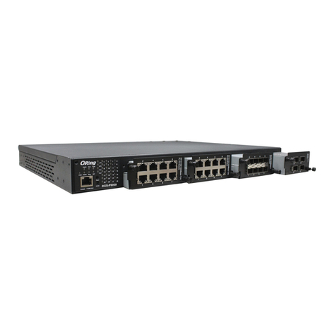
ORiNG RGS-PR9000 User manual

ORiNG

ORiNG RGS-PR9000 User manual

ORiNG RGPS-9084GP-P User manual

ORiNG

ORiNG RGPS-9084GP-P User manual

ORiNG RES-P3242GCL SERIES User manual

ORiNG

ORiNG RES-P3242GCL SERIES User manual

ORiNG RES-9242GC User manual

ORiNG

ORiNG RES-9242GC User manual

ORiNG IES-2042 Series User manual

ORiNG

ORiNG IES-2042 Series User manual

ORiNG IES-P3073GC Series User manual

ORiNG

ORiNG IES-P3073GC Series User manual

ORiNG RGPS-92222GCP-NP-LP User manual

ORiNG

ORiNG RGPS-92222GCP-NP-LP User manual

ORiNG TGPS-9164GT-M12X-BP2-MV User manual

ORiNG

ORiNG TGPS-9164GT-M12X-BP2-MV User manual

ORiNG IGCS-E131GP User manual

ORiNG

ORiNG IGCS-E131GP User manual

ORiNG IES-1080A User manual

ORiNG

ORiNG IES-1080A User manual

ORiNG IGS-3032GC User manual

ORiNG

ORiNG IGS-3032GC User manual

ORiNG IPS-2042FX Series User manual

ORiNG

ORiNG IPS-2042FX Series User manual

ORiNG TAR-120-M12 User manual

ORiNG

ORiNG TAR-120-M12 User manual

ORiNG TGAR-1062PLUS-3GS-M12 User manual

ORiNG

ORiNG TGAR-1062PLUS-3GS-M12 User manual

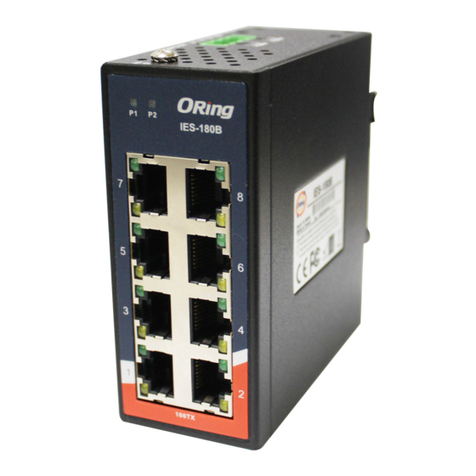
ORiNG IES-180B User manual

ORiNG

ORiNG IES-180B User manual

ORiNG RGS-92222GCP-NP Series User manual

ORiNG

ORiNG RGS-92222GCP-NP Series User manual

ORiNG RGS-9244GP User manual

ORiNG

ORiNG RGS-9244GP User manual

ORiNG RGPS-7244GP User manual

ORiNG

ORiNG RGPS-7244GP User manual

ORiNG RGPS-7244GP-P User manual

ORiNG

ORiNG RGPS-7244GP-P User manual

ORiNG iar-120 series User manual

ORiNG

ORiNG iar-120 series User manual

ORiNG IES-3162GC Series User manual

ORiNG

ORiNG IES-3162GC Series User manual

ORiNG TGAR-1062-M12-3G User manual

ORiNG

ORiNG TGAR-1062-M12-3G User manual

Popular Network Router manuals by other brands

Phocos CX-V1.1 user manual

Phocos

Phocos CX-V1.1 user manual

Billion BiPAC 7300M user manual

Billion

Billion BiPAC 7300M user manual

D-Link DWR-M960 user manual

D-Link

D-Link DWR-M960 user manual

HMS Anybus AWB5121 Startup guide

HMS

HMS Anybus AWB5121 Startup guide

CARVIN PB48 instructions

CARVIN

CARVIN PB48 instructions

NETGEAR JNR3210 Guide d'installation

NETGEAR

NETGEAR JNR3210 Guide d'installation

AudioCodes Mediant MSBR Series reference guide

AudioCodes

AudioCodes Mediant MSBR Series reference guide

ActionTec GT704-WG Troubleshooting

ActionTec

ActionTec GT704-WG Troubleshooting
NetComm 3G38WV user guide

NetComm

NetComm 3G38WV user guide

Conceptronic C150APRA2 user manual

Conceptronic

Conceptronic C150APRA2 user manual

TP-Link TD-8817 user manual

TP-Link

TP-Link TD-8817 user manual

ICP DAS USA MSM-508 user manual

ICP DAS USA

ICP DAS USA MSM-508 user manual

Amit AIPQB1215WA61/01 Operation manual

Amit

Amit AIPQB1215WA61/01 Operation manual

TRENDnet SMCWBR14S-NL user manual

TRENDnet

TRENDnet SMCWBR14S-NL user manual

HPE FlexNetwork 5510 HI Series Macsec configuration guide

HPE

HPE FlexNetwork 5510 HI Series Macsec configuration guide

Juniper MX104 Hardware guide

Juniper

Juniper MX104 Hardware guide

AOpen AOI-891 user manual

AOpen

AOpen AOI-891 user manual

ActronAir LM7 operating instructions
ActronAir

ActronAir LM7 operating instructions

manuals.online logo
manuals.online logoBrands
  • About & Mission
  • Contact us
  • Privacy Policy
  • Terms and Conditions

Copyright 2025 Manuals.Online. All Rights Reserved.