Orion L77-17 User manual

MODEL L77-17
SERIAL # ____-_______
2270 Industrial boul. , Montreal (Laval), Canada, H7S 1P9
Tel.: (450) 667-9769, Fax: (450) 667-6320

INSTRUCTION
MANUAL
FOR ALL INQUIRIES
PLEASE CONTACT
OUR LOCAL DISTRIBUTOR
FOR NORTH AMERICA ONLY
1-800-333-6556

Thank you for choosing ORION stretch-wrapping equipment. It is a wise choice, which
will benefit your company now and in the future.
ORION uses a unique combination of functional, rugged steel structure and
sophisticated control systems to offer equipment high in durability and low in maintenance
requirements. Our advance control systems mean that Orion equipment can be operated
safely and efficiently without the need for special operator expertise.
Please read this manual carefully and keep it handy. Following these simple operating
instructions will insure the safe and efficient performance of this machine while simple
maintenance procedures will guarantee a long and productive life of the equipment.
Notice:
Our manual covers standard features of the machine. Certain options may not be
fully covered due to their unique application.
In order to acquire more information about custom made features of your machine and to
provide quicker service, the following information is required when making an inquiry:
1)Model
2)Serial Number
3)Subassembly ( see PART LIST )
SAFETY:
ORION'S stretch wrappers should be operated with caution and common sense as any other
industrial equipment. To prevent injury and/or electrical shocks, careful operation of the machine and
awareness of its many automatic functions is required.
NOTE: All electrical power and compressed air must to be disconnected prior to all
inspection, maintenance or repair work.
ORION PACKAGING INC.

ORION PACKAGING SYSTEMS INC.
SEMI-AUTOMATIC SPECIFICATIONS
ORION EPIC®SERIES MODEL L-77
Spiral Semi-Automatic Medium Duty Low Profile
Maximum Load Size 55”W x 55”L x 84”H
Weight Capacity 4,000 Ibs. Dynamic, 20,000 Ibs. Static
Utilities 115 / 1 / 60 ; 15 Amp Service
Turntable 59” Diameter Structural Steel Plate
Dura-Glide™Turntable Support System
Quiet in Operation, Maintenance Free
3” Height Floor to Top of Turntable
Turntable Drive 0-12 RPM Variable Turntable Speed
Variable Speed Drive Motor
Heavy Duty Chain Drive with Tensioner
Electronically Adjustable Acceleration/Deceleration (Soft Start)
Positive Alignment Feature
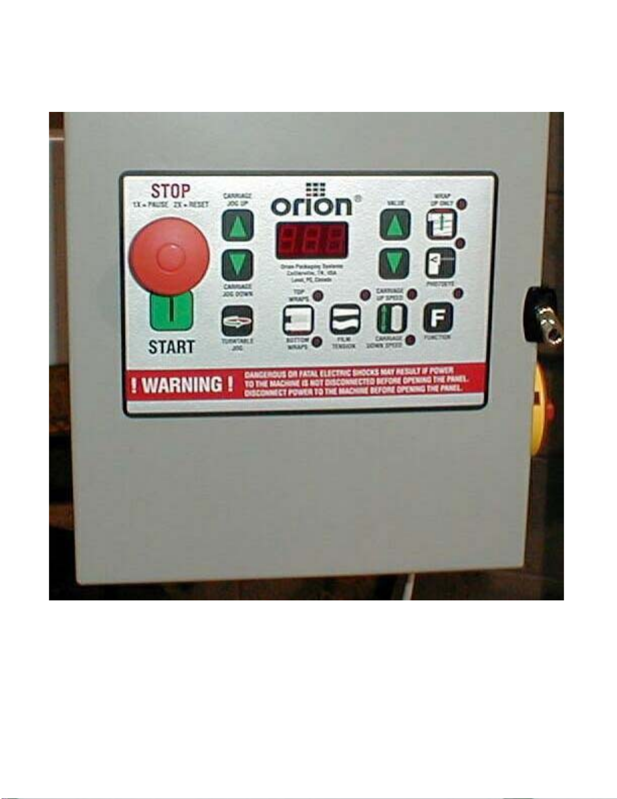
Control Features CSA Approved, NEMA 12 Control Panel
State-of-the-Art Logic Control
User Friendly Microprocessor with Micro-Switch Keypad
Revo-Logic™Exact Wrap Counting Technology
Electronic Film Tension Control Adjustment on the Panel
Separate Top I Bottom Wrap Count Selectors with LED Count Display
Variable Speed Film Carriage Up/Down Control
Film Carriage Raise/Lower Switch (Manual)
Photocell for Automatic Load Height Detection
Turntable Jog Pushbutton
Film Delivery 20” Insta-Thread LT Powered Pre-Stretch Film Delivery System
260% Pre-Stretch Ratio
Easy & Safe to Operate Self-Threading Carriage Design
Variable Speed Film Output (Non-Wearing Sensor)
Heavy Duty Chain & Sprocket Ratio Control
Adjustable Film Roping Bar on Chassis for Stronger Interlocking of Load and Pallet
Film Carriage Elevator Drive Heavy Duty ANSI Chain Carriage Lift
Variable Speed Drive Motor
Multi-Point UHMW Precision Carriage Guidance System
Structural Features 100% Structural Steel Construction Throughout
Easy Access to All Components
Open Mechanical Design for Ease of Maintenance
Forklift Portable Base Design
Structural Steel Tube Mast Design
Hinged Mast for Ease of Shipping, Portability
Estimated Shipping Weight 1,500 Ibs.
Visit our Distributor Support Website at www.support@orionpackaging.com

MACHINE UNLOADING
INSPECTION & INSTALLATION
UNLOADING
Machine can be easily unloaded and transported by a forklift with a minimum capacity of 2500 lbs.
1. Carefully insert the forks into the lifting tubes to the maximum possible depth. Depending on the model, a forklift access
may be either at the turntable end of the machine frame, the tower end or both. In case of the mongoose machine enter
the forks under the frame or insert the forks in the tube brackets welded to the top of the machine.
2. Lift the machine (or other part of system) only to the necessary height to move it with no bouncing or friction on the
floor.
3. Sit the machine down assuring uniform contact with the floor, which is necessary to ensure correct and smooth
operation.
INSPECTION
1. Remove all packing and supporting additions - these may include the blocks under the carriage and the restraining bar
over the table. NOTE: when removing the stretchwrap film covering the machine, care must be taken not to cut any of
the electrical wires and/ or polyurethane covering on the film carriage rollers.
2. Perform a visual inspection of the electrical and mechanical parts for loosened joints and / or broken connections. Any
suspected shipping damage must be reported immediately to the freight carrier. Any transport damage cannot be claimed
to Orion Packaging Inc.
Items that are vulnerable to damage and must be inspected are as follows:
- Motors and transmissions
- Junction boxes
- Electrical conduits
- Proximity and limit switches
- Photocells
3. Check under the turntable to ensure that there is no crippling of the movable parts i.e. casters, center axle or drive assembly.
4.Verify the following:
- Turntable or rotary arm drive system to confirm that the reducer to drive the chain is snug and properly aligned.
- Verify the wires tight conduits for crushed sections or loose fittings.
- Verify the film carriage to be sure that it is correctly aligned with the tower
- Verify the tension on the lift chain.
- Verify all the dials and knobs on the control panel for smooth action.
MACHINE INSTALLATION
After the visual inspection has been completed, the electrical power and the compressed air shall be connected as
specified on the diagrams supplied with the machine.
An electrical diagram is provided with each machine in the envelope attached to the panel box.
ASSEMBLY PROCEDURE
The structural frames of the machine have to be installed on a leveled floor. Locate the main wrapper section into its final
position, keeping the tower assembly* away from any traffic. The wrapper mainframe section must be bolted to the floor
by the 1/2” concrete floor anchors (leg & shield or expandable type).
Any wiring that has been disconnected to facilitate transport is marked with a number located on the junction box to which
the wiring must be reconnected. Any wire run that appears too short or long may indicate that the position of the
mechanical components is incorrect. Verify the status of all assemblies before proceeding.
* The tower deviation from vertical must not exceed 1/4” on the distance of 10 feet (angle: 0 degrees 6’).
CONTROL PANEL
In the case of the free standing panel (console) place it adjacent to the system and anchor firmly to the floor. Connect the
liquid tight (rigid conduit) to the main junction box located on the wrapper main frame next to the tower.


Fig. 1 Keyboard/Display

Fi
g
.
2
755.2
Micro
p
rocesso
r
Boa
r
d&
755.1
Ke
y
boa
r
d
Turntabl
e
Momenta
r
y
Positio
n
Senso
r
Carriag
e
Dow
nRibbon
Cabl
e
TT Start Stop
Photocell
Carriag
e
Ru
n
Carriag
e
U
p

Fi
g
.
3
MCI
A
Connection
s
T
B
4
Mai
n
Interconnec
t
Terminal
s
Carriag
e
Moto
r
Armatur
e
Connectio
n
Turntabl
e
Moto
r
Armatur
e
Connectio
n
Multistretc
h
Moto
r
Armatur
e
Connectio
n
Reversing
Relays
Multistretc
h
(Fil
m
Delive
r
y
Control
)

Fi
g
. 4
Th
e
Complet
e
755
A
ssembl
y

Fi
g
5
Carriag
e
Contro
l
Multistretc
h
Contro
l
Turntabl
e
Contro
l

755 Orion Integrated Digital Control Center
OPERATING
INSTRUCTIONS
HL77-17

TABLE OF CONTENTS
SECTION 1 GENERAL DESCRIPTION..........................................................................2
1.1 Reference drawing .................................................................................2
1.2 Description of sub-assemblies................................................................ 2
1.3 Multistretch control description...............................................................3
1.4 Turntable control description ..................................................................4
1.5 Carriage control description.................................................................... 4
SECTION 2 KEYBOARD DESCRIPTION ....................................................................... 5
SECTION 3 MANUAL OPERATION................................................................................6
3.1 Turntable jog ..........................................................................................6
3.2 Carriage jog up & down..........................................................................6
SECTION 4 PROGRAMMING OF WRAPPING PATTERNS ..........................................6
4.1 Top & bottom wrap.................................................................................6
4.2 Film tension............................................................................................ 7
4.3 Carriage up & down speed.....................................................................7
4.4 Spiral up / up & down .............................................................................7
4.5 Photo eye............................................................................................... 8
4.6 Default setting ........................................................................................8
SECTION 5 MODE OF OPERATION..............................................................................8
5.1 Cycle start ..............................................................................................8
5.2 Pause / stop ...........................................................................................8
SECTION 6 ADVANCED PARAMETERS SETTING.......................................................9
6.1 Parameter description ............................................................................9
6.2 Accessing parameters............................................................................ 9
6.3 Parameter saving ...................................................................................9
6.4 Get default settings.................................................................................10
6.5 Exit function............................................................................................10
SECTION 7 DISPLAY SCREEN......................................................................................10
7.1 Display contents.....................................................................................10
7.2 Display refresh .......................................................................................10
SECTION 8 MAINTENANCE........................................................................................... 11
8.1 Replacing sub assemblies......................................................................11
8.2 Board-level maintenance........................................................................ 11
SECTION 9 TROUBLE-SHOOTING................................................................................11
SECTION 10SPARES PARTS .........................................................................................12
Page 1

SECTION 1
General Description
The system is an integrated control for a stretchwrapping machine. It includes three DC
motor controls:
•Carriage control, reversing.
•Turntable control, fully programmable via keyboard interface.
•Multistretch control, fully programmable via keyboard interface.
The 755 control comprises three principal sub-assemblies:
•Keyboard and display - for setting and viewing the system parameters. (Type 755.1 Fig. 1)
•Microprocessor board - overall system control (Type 755.2 Fig. 2)
•Motor control and interface assembly (MCIA) (Type 755.3 Fig. 3)
These items are mounted and wired inside of enclosure or front panel plate mounted to the
machine. The membrane switch/display operator interface is on the door of this enclosure.
1.1 Reference Drawings
DWG. # 302 452 rev. 2
DWG. # 302 453 rev. 2
1.2 Description of Sub-Assemblies
•KEYBOARD AND DISPLAY Type 755.1
This board contains 12 keypads and three, seven-segment display modules (three
digits). It is used to start an automatic wrapping cycle, or to operate the machine
manually, and also to set and adjust the control parameters (carriage speed, film
tension value, and turntable speed, etc.). It is mounted on the enclosure door, behind
the membrane label. The keyboard communicates with the microprocessor board
through a 28-pin connector (P1).
•MICROPROCESSOR BOARD Type 755.2
Contains the system microprocessor, E2PROM memory. This board generates the
reference and control signals for the three machine drives: carriage, turntable and
multistretch. It plugs into, and mounts behind the keyboard/display, connected to the
MCIA by a 20-way ribbon cable.
•MOTOR CONTROL AND INTERFACE ASSEMBLY (MCIA) Type 755.3
This assembly comprises of a motherboard, power supplies and card rack, which is
plugged into three distinct DC motor controls. This DC motor control regulates the
function of the machine (multistretch, turntable and carriage). The motherboard houses
the reversing relays for the carriage, and connectors to interface with machine. It also
includes two regulated DC supplies - +5 VDC for the microprocessor board, and
+24VDC for the hall effect device (which senses position of multistretch dancer roller
and photocell).
Page 2

1.3 Multistretch control description
The multistretch drive is a solid state DC motor control especially designed for use in
constant tension mode on stretchwrapping machines. The unit functions as a pay-off
drive, unwinding the pre-stretched film as the turntable and pallet rotate, and
continuously regulating tension as the diameter of the wrapped load changes. Since the
typical pallet load is a square cross section, the effective diameter changes abruptly with
rotation; the film tension is monitored by a tension-arm, held in place by spring pressure.
As the film tension changes, the arm moves, rotating a cam, and the cam orientation is
sense by a hall effect transducer. The transducer is powered at 24VDC by a regulated
supply on the MCIA. The transducer signal varies with the separation between its
sensing head and the cam surface – the output range is from approximately 0.5 to 3.5
volts DC. The amplified transducer signal controls motor torque, increasing or
decreasing it so as to restore the tension arm to its previous position, and to maintain
tension at its preset level. The system response is tailored so that these small
corrections are smooth, continuous and largely imperceptible. The tension defaults to
minimum when the external tension adjustment circuit is opened.
ADJUSTMENTS:
The operator, using the digital interface can set the film tension. In addition to the
above-mentioned digital tension adjustment, there are three trimming potentiometers.
The trimmers are accessible through the faceplate of the plug-in control, (See Fig. 3),
functions as follows:
ZERO (RV1)
This control injects an offset voltage, which adds or subtracts from the tension voltage
reference; this will allow the extremes of adjustment from the digital interface to be set to
levels consistent with appropriate operation. Typically, the “Zero” will be used to center
the operating range in the linear portion of its characteristics. This adjustment is normally
made at the factory and should not require field adjustment. The machine should be
stopped and the film removed for this adjustment.
SPAN (RV2)
This controls the system loop gain, and may be adjusted if the motor continues to turn
when the dancer arm is unloaded. The potentiometer should be adjusted to ensure that
the motor is de-energized when arm is unloaded.
CURRENT LIMIT
To protect the unit against damage, if the motor should stall, jam, or current demands
exceed the rating, a current-limiting circuit is included which keeps motor current at a
safe level regardless of motor load, or input from the tension arm. The current limit is set
at the factory and should not require field adjustment.
CONNECTION
The motor armature attaches to terminals (+) (-) are accessible through the faceplate of
the plug-in module. The unit is suitable for permanent magnet shunt style DC motors
with 90 V armature rating, sized at up to 3/4HP.
Page 3

1.4 Turntable control description
The turntable control is a DC motor control designed for the use as a turntable drive of
wrapping machines, where long and repeatable acceleration and deceleration times is
needed, and remotely selectable pre-set speeds are required. The unit requires a 90 V
armature, permanent magnet DC motor as output device.
CURRENT LIMIT
To protect the unit against damage, if the motor should stall, jam, or current demands
exceed the rating, a current-limiting circuit is included which keeps motor current at a
safe level regardless of motor load. The current limit is set at the factory and should not
require field adjustment.
CONNECTION
The motor armature attaches to quick disconnect terminals (+) (-) are accessible
through the faceplate of the plug-in module. The unit is suitable for permanent magnet
shunt style DC motors with 90 V armature rating, sized at up to 3/4HP.
1.5 Carriage control description
The carriage control is a DC motor control designed to operate in direct or reversing
mode at preset speeds defined by the user through the keyboard section. The unit
requires a 90 V armature, permanent magnet DC motor as output device.
Two relays and a dynamic braking resistor (DBR) are used for motor reversing and
braking. The brake resistor is bolted to a card-rack side plate, part of the MBIA. The
circuit is equipped with anti-plug protective interlocks.
CURRENT LIMIT
To protect the unit against damage, if the motor should stall, jam, or current demands
exceed the rating, a current-limiting circuit is included which keeps motor current at a
safe level regardless of motor load. The current limit is set at the factory and should not
require field adjustment.
CONNECTION
The motor armature attaches to quick-disconnect terminals (+) (-), on the MBIA
motherboard. The unit is suitable for permanent magnet shunt style DC motors with 90
V armature rating, sized at up to 3/4HP.
Page 4

SECTION 2
Keyboard Description
The keyboard is used to control and monitor all the parameters of a stretch wrapper
machine. It will also be used for in house calibration. See Fig 1. Below is a short
description for the purpose of each keypad element.
•START
The start keypad is used to start or continue a wrapping cycle.
•E-STOP
The stop push-button is used to pause and stop a wrapping cycle before it is completed.
•TURNTABLE JOG
The jog keypad is used to jog the turntable manually at a preset speed.
•CARRIAGE RAISE
The carriage up keypad is used to move the carriage up manually.
•CARRIAGE LOWER
The carriage down keypad is used to move the carriage down manually.
•WRAPS
This keypad is used to program the number of top and bottom wraps that the turntable will
perform during a wrapping cycle.
•TENSION
This keypad will set the tension of the wrapping film.
•CARRIAGE SPEED
This keypad is used to set the carriage up and down speed.
•FUNCTION
This keypad is used for in house programming and adjustments. Access is limited to
authorised personnel by a password code.
•SPIRAL
This keypad is used to select between “UP/DOWN” and “UP ONLY” spiral wrapping
patterns
•PHOTOCELL
This keypad is used to enable and disable the load auto-height photocell.
•VALUE UP and DOWN Arrows
Those keypads are used to change the value of parameters displayed on the SSD.
Page 5

SECTION 3
Manual Operation
3.1 Turntable Jog
To rotate the Turntable using the TURNTABLE JOG keypad, the machine must be
stopped (out of wrapping cycle). If a cycle is being processed, this keypad is disabled.
When the JOG keypad is pressed, the turntable turns at a preset speed (Low) until the
keypad is released. Screen displays JOG.
3.2 Carriage Jog UP & DOWN
To move the carriage up or down using the CARRIAGE UP and CARRIAGE DOWN
keypad, the machine must be stopped (out of wrapping cycle). If a cycle is being
processed, those two keypads are disabled.
When the CARRIAGE UP keypad is pressed, the carriage will go up until the keypad is
released or the carriage top limit switch is activated. Screen displays UP.
When the CARRIAGE DOWN keypad is pressed, the carriage will go down and it will
stop only when carriage down keypad is pressed again or carriage up keypad is
pressed, or when it reaches the carriage bottom limit switch. Screen displays dn.
A delay of one (1) second must elapse before the carriage can reverse direction.
SECTION 4
Programming Wrapping Pattern
This section describes how to change all programmable parameters and values. Also,
operator can select up to three (3) wrapping modes by using the spiral keypad and the
function parameter P02:
•Spiral Up Only
•Spiral Up/Down with top wraps first
•Spiral Up/Down with bottom wraps first.
4.1 Top & Bottom Wraps
There are two settings for the number of wraps. The numbers of wraps are executed
at the bottom and at the top of the load.
To select the top wrap variable, the set # wraps keypad must be pressed once, this
turns ON the LED located beside the top right corner of the keypad. This indicates that
the top wrap variable is selected. By using the UP or DOWN arrows the value can be
changed. The value can be set from 1 to 10.
To select the bottom wrap variable, the set # wraps keypad must be pressed twice or
until the LED located beside the bottom right corner is ON. This indicates that the
bottom wrap variable is selected. By using the UP or DOWN arrows the value can be
changed. The value can be set from 1 to 10.
For changes “on-the-fly”, a delay of 1 (one) second must elapse before new top/bottom
wraps settings will be effective
Page 6

4.2 Film Tension
To select the film tension variable, press the FILM TENSION keypad. The FILM
TENSION LED is located at the top right corner of the keypad. Once the keypad is
pressed and the LED is ON, the UP and DOWN arrows can be used to change the
value. The value may be set from 0 to 100 (0 -100%).
4.3 Carriage UP & DOWN Speed
There are two settings for the carriage speed: the CARRIAGE UP and the CARRIAGE
DOWN speeds.
By pressing once on the carriage speed keypad, the LED located at the top right
corner of the keypad will turn ON. This means that the carriage speed up variable is
selected. By using the UP or DOWN keypad arrows the value can be changed.
The value will vary from 0 to 100 (0-100%).
To select the CARRIAGE DOWN variable, the CARRIAGE SPEED keypad must be
pressed twice or until the LED located at the bottom right corner is ON. By using the
UP or DOWN keypad arrows the value can be changed.
The value will vary from 0 to 100 (0-100%).
4.4 Spiral UP / UP & DOWN
Pressing up only keypad, it will switch between “spiral up only” and “spiral up & down”.
When LED is ON, the “spiral up only” mode is selected and the sequence will be:
1. Film carriage wraps bottom of load with selected number of bottom wraps
2. Film carriage moves up until top of load is reached
3. Applies selected number of top wraps
4. Turntable decelerates and stops in home position
When LED is OFF, the “spiral up & down” mode is selected and the sequence will be
according to the value of the advanced parameter P02 (see section 6 for setting of
P02).
If “top wraps first” is selected (P02=0)
1. Film carriage moves until top of load is reached
2. Applies selected number of top wraps
3. Film carriage moves to the bottom of load
4. Applies selected number of bottom wraps
5. Turntable decelerates and stops in home position
If “bottom wraps first“ is selected (P02=1)
1. Applies selected number of bottom wraps
2. Film carriage moves until top of load is reached
3. Applies selected number of top wraps
4. Film carriage moves to the bottom of load
5. Turntable decelerates and stops in home position
Page 7
Table of contents
Other Orion Industrial Equipment manuals

Orion
Orion SPECTRA LP User manual

Orion
Orion AdBlue 75020 User manual

Orion
Orion AllSky 52187 User manual

Orion
Orion H66R-17 User manual

Orion
Orion 24555 User manual

Orion
Orion 39068 User manual

Orion
Orion H66-14 User manual

Orion
Orion L77-VP User manual

Orion
Orion H77-VP User manual

Orion
Orion CTS67-20 User manual
Popular Industrial Equipment manuals by other brands

SDX Audio
SDX Audio THERMOBOX quick start guide

Eaton
Eaton Airflex WCB Series Installation, operation and maintenance

M&C
M&C PSS Series instruction manual

SCHUNK
SCHUNK ERT 100 Translation of original operating manual

ThyssenKrupp
ThyssenKrupp Drive DAB530 operating manual

Emerson
Emerson Spence Max-Flo Series instruction manual