Orion L77S-20 User manual

MODEL L77S-20
SERIAL # 2007-8899999
2270 Industrial boul. , Montreal (Laval), Canada, H7S 1P9
Tel.: (450) 667-9769, Fax: (450) 667-6320

2
INSTRUCTION
MANUAL
FOR ALL INQUIRIES
PLEASE CONTACT
OUR LOCAL DISTRIBUTOR
FOR NORTH AMERICA ONLY
1-800-333-6556

3
Thank you for choosing ORION stretch-wrapping equipment. It is a wise choice, which will
benefit your company now and in the future.
ORION uses a unique combination of functional, rugged steel structure and
sophisticated control systems to offer equipment high in durability and low in maintenance
requirements. Our advance control systems mean that Orion equipment can be operated
safely and efficiently without the need for special operator expertise.
Please read this manual carefully and keep it handy. Following these simple operating
instructions will insure the safe and efficient performance of this machine while simple
maintenance procedures will guarantee a long and productive life of the equipment.
Notice:
Our manual covers standard features of the machine. Certain options may not be
fully covered due to their unique application.
In order to acquire more information about custom made features of your machine and to
provide quicker service, the following information is required when making an inquiry:
1)Model
2)Serial Number 2007-8899999
3)Subassembly ( see PART LIST )
SAFETY:
ORION'S stretch wrappers should be operated with caution and common sense as any other
industrial equipment. To prevent injury and/or electrical shocks, careful operation of the machine and
awareness of its many automatic functions is required.
NOTE: All electrical power and compressed air must to be disconnected prior to all
inspection, maintenance or repair work.
ORION PACKAGING INC.

4
ORION PACKAGING SYSTEMS INC.
SEMI-AUTOMATIC SPECIFICATIONS
ORION EPIC®SERIES MODEL L-77S
Spiral Semi-Automatic Medium Duty Low Profile w/Surrounding Steel Deck Frame
Maximum Load Size 55”W x 55”L x 84”H
Weight Capacity 4,000 Ibs. Dynamic, 20,000 Ibs. Static
Utilities 115 / 1 / 60 ; 15 Amp Service
Turntable 59” Diameter Structural Steel Plate
Dura-Glide™Turntable Support System, Quiet in Operation, Maintenance Free
3” Height Floor to Top of Turntable
Turntable Drive 0-12 RPM Variable Turntable Speed
Variable Speed Drive Motor
Heavy Duty Chain Drive with Tensioner
Electronically Adjustable Acceleration/Deceleration (Soft Start)
Positive Alignment Feature
Control Features CSA Approved, NEMA 12 Control Panel
State-of-the-Art Logic Control
User Friendly Microprocessor with Micro-Switch Keypad
Revo-Logic™Exact Wrap Counting Technology
Electronic Film Tension Control Adjustment on the Panel
Separate Top I Bottom Wrap Count Selectors with LED Count Display
Variable Speed Film Carriage Up/Down Control
Film Carriage Raise/Lower Switch (Manual)
Photocell for Automatic Load Height Detection
Turntable Jog Pushbutton
Film Delivery 20” Insta-Thread LT Powered Pre-Stretch Film Delivery System
200% Pre-Stretch Ratio
Easy & Safe to Operate Self-Threading Carriage Design
Electronic Film Tension Control Adjustment on the Panel
Variable Speed Film Output (Non-Wearing Sensor)
Heavy Duty Chain & Sprocket Ratio Control
Adjustable Film Roping Bar on Chassis for Stronger Interlocking of Load and Pallet
Film Carriage Elevator Drive Heavy Duty ANSI Chain Carriage Lift
Variable Speed Drive Motor
Multi-Point UHMW Precision Carriage Guidance System
Structural Features 100% Structural Steel Construction Throughout
Easy Access to All Components
Open Mechanical Design for Ease of Maintenance
Forklift Portable Base Design
Structural Steel Tube Mast Design
Hinged Mast for Ease of Shipping, Portability
Estimated Shipping Weight 1,500 Ibs.
Visit our Distributor Support Website at www.support.orionpackaging.com

5
MACHINE UNLOADING
INSPECTION & INSTALLATION
UNLOADING
Machine can be easily unloaded and transported by a
forklift with a minimum capacity of 2500 lbs.
1. Carefully insert the forks into the lifting tubes to the
maximum possible depth. Depending on the model, a
forklift access may be either at the turntable end of the
machine frame, the tower end or both. In case of the
mongoose machine enter the forks under the frame or
insert the forks in the tube brackets welded to the top of
the machine.
2. Lift the machine (or other part of system) only to the
necessary height to move it with no bouncing or friction on
the floor.
3. Sit the machine down assuring uniform contact with the
floor, which is necessary to ensure correct and smooth
operation.
INSPECTION
1. Remove all packing and supporting additions - these
may include the blocks under the carriage and the
restraining bar over the table.
NOTE: when removing the stretchwrap film covering the
machine, care must be taken not to cut any of the
electrical wires and/ or polyurethane covering on the film
carriage rollers.
2. Perform a visual inspection of the electrical and
mechanical parts for loosened joints and / or broken
connections. Any suspected shipping damage must be
reported immediately to the freight carrier. Any transport
damage cannot be claimed to Orion Packaging Inc.
Items that are vulnerable to damage and must be
inspected are as follows:
- Motors and transmissions
- Junction boxes
- Electrical conduits
- Proximity and limit switches
- Photocells
3. Check under the turntable to ensure that there is no
crippling of the movable parts i.e. casters, center axle or
drive assembly.
4.Verify the following:
- Turntable or rotary arm drive system to confirm that the
reducer to drive the chain is snug and properly aligned.
- Verify the wires tight conduits for crushed sections or
loose fittings.
- Verify the film carriage to be sure that it is correctly
aligned with the tower
- Verify the tension on the lift chain.
- Verify all the dials and knobs on the control panel for
smooth action.
MACHINE INSTALLATION
After the visual inspection has been completed, the
electrical power and the compressed air shall be
connected as specified on the diagrams supplied with the
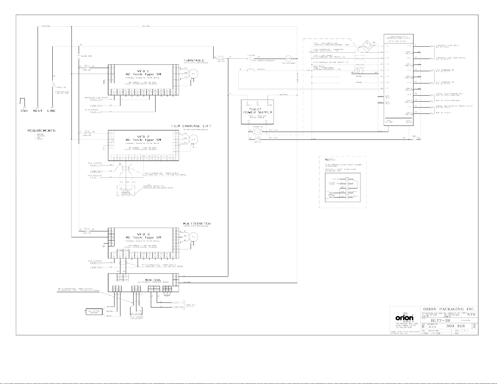
machine. An electrical diagram is provided with each
machine in the envelope attached to the panel box.
ASSEMBLY PROCEDURE
The structural frames of the machine have to be installed
on a leveled floor. Locate the main wrapper section into its
final position, keeping the tower assembly* away from any
traffic. The wrapper mainframe section must be bolted to
the floor by the 1/2” concrete floor anchors (leg &
shield or expandable type).
Any wiring that has been disconnected to facilitate
transport is marked with a number located on the junction
box to which the wiring must be reconnected. Any wire run
that appears too short or long may indicate that the
position of the mechanical components is incorrect. Verify
the status of all assemblies before proceeding.
* The tower deviation from vertical must not exceed 1/4”
on the distance of 10 feet (angle: 0 degrees 6’).
CONTROL PANEL
In the case of the free standing panel (console) place it
adjacent to the system and anchor firmly to the floor.
Connect the liquid tight (rigid conduit) to the main junction
box located on the wrapper main frame next to the tower.
Before Starting Machine Operation
Verify that the machine is properly connected to the
electrical source. The electrical requirements depend on
the machine type and features. For this information,
please see the machine electrical diagram provided with
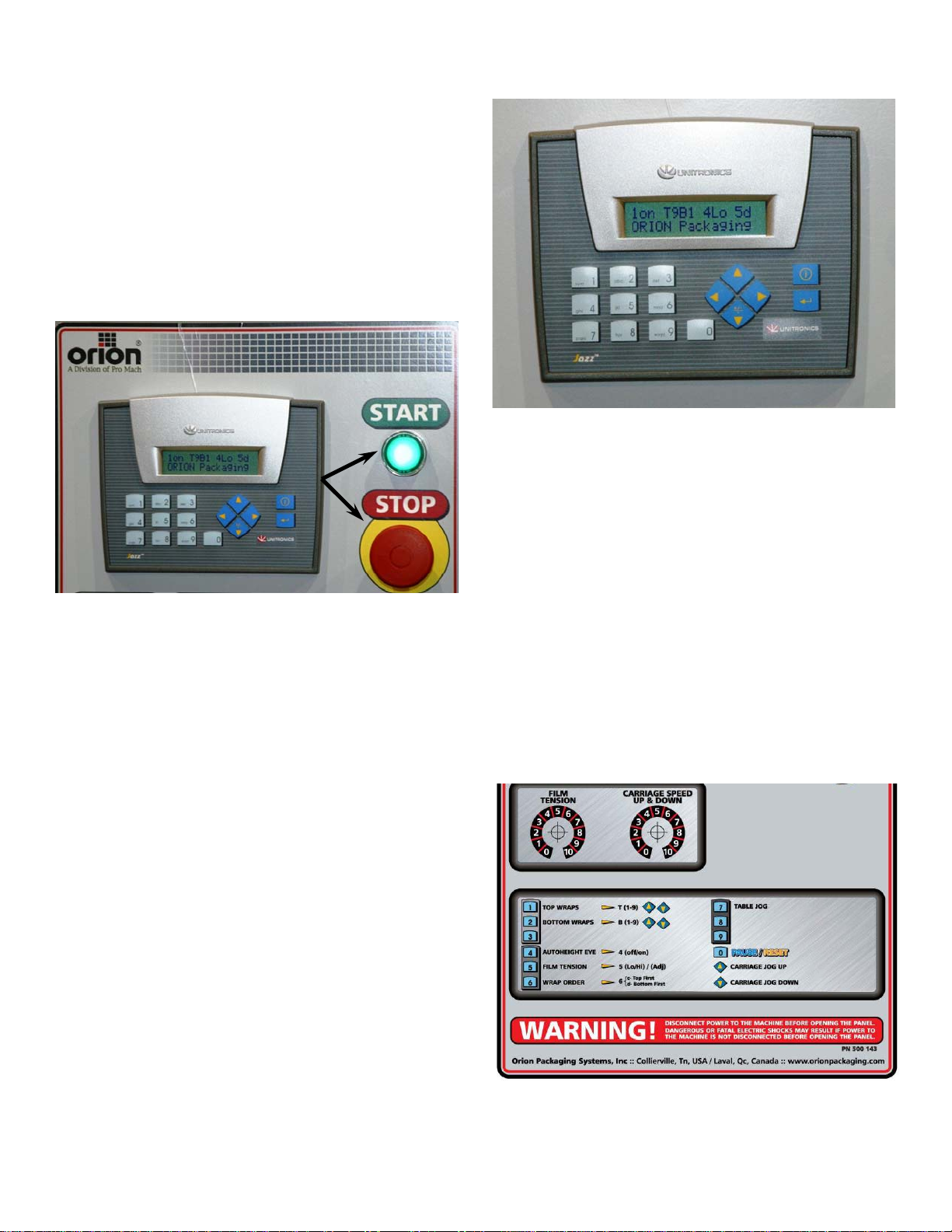
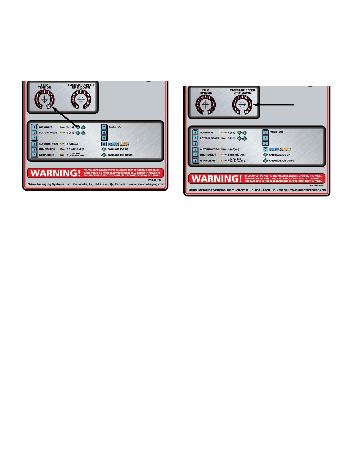
the machine operation manual. The control panel layout
for the machine is shown on the drawing.
CAUTION: Before preceding the machine operation
familiarize yourself with the EMERGENCY-STOP button
and all functions, switches and pushbuttons.

6

7
Note: For VFD adjustment, please contact Orion Packaging service department.

8

9
MACHINE OPERATION
POWER SWITCH
Located on the panel door or side of the panel box, the
lockable power switch has two settings:
ON - connects a power source to the machine
OFF - disconnects the power source.
START AND EMERGENCY STOP SWITCHES
The START switch is used to start the cycle once the load
is on the turntable. The cycle may be stopped at anytime
by pressing the STOP button. (see Figure 1)
Figure 1
NOTICE: The STOP button interrupts the entire machine
electrical circuits. To continue the cycle the STOP
push/pull button should be pulled out and START button
pressed for the machine to restart. Double pressing the
push – pull STOP button will reset the machine program
and machine will be ready to apply the wrapping cycle
from the beginning.
SETTING-UP MACHINE PARAMETERS
Note: Parameter change is available when machine is
not in cycle.
1- TOP WRAPS 1,2,3...9
Press button #1 on the keypad to select “Top Wrap”, then
using the arrows on the keyboard select between 1 to 9
for required number of wraps on top of the load.
2- BOTTOM WRAPS 1,2,3...9
Press button #2 on the keypad to select “Bottom Wrap”,
then using the arrows on the keyboard select between 1 to
9 for required number of wraps at the bottom of the load.
Note: Refer to the list of options at the bottom of the panel
sticker for reference. (see Figure 3)
Figure 2
3- NOT USED
4- AUTOHEIGHT EYE
Press button #4 on the keypad to switch from ON to OFF,
or vice-versa.(see Figure 2)
ON - When ON, the photocell is activated to automatically
detect top of the load. The carriage will automatically stop
at the top of the load regardless of its height.
OFF - When OFF, the photocell is inoperative and
carriage will travel to the top limit switch regardless of its
height.
NOTE: For proper machine operation, top limit switch
position should be adjusted to desired level prior to
starting the cycle.
Figure 3

10
5- FILM TENSION
( High/Low tension switching button #5 is not applicable on this
model, this is exclusive function on L77e models)
Film tension may be adjusted using the film tension control
knob (see Figure 4). The range of tension is from 0 to 10 (0
to 4 the low range, 4 to 8 the most selected range for most of
the films used by our customers, 8 to 10 as a very high range
which may break some types of films).
Figure 4
6- WRAPPING ORDER ;
TOP FIRST OR BOTTOM FIRST
Press button #6 on the keypad to switch from BOTTOM
WRAPS FIRST to TOP WRAPS FIRST, or vice-versa.
TOP WRAPS FIRST - When this Sub-Mode has been
selected film carriage will move to top of load and stop.
Selected number of top wraps will be applied. The film
carriage will then move to bottom of the load and stop.
Selected number of bottom wraps will then be applied.
The film carriage will remain in bottom position; turntable
will slow down and stop in home position.
BOTTOM WRAPS FIRST - When this Sub-Mode has
been selected machine will first wrap bottom of load
applying selected number of bottom wraps. The film
carriage will then move to top of load and stop. Selected
number of top wraps will then be applied. The film carriage
will move down to bottom position, after which the
turntable will slow down and stop in home position.
7- TURNTABLE JOG
The turntable jog can operate only when machine is not in
cycle. The turntable jog will rotate at a low speed when the
button #7 is held down, when released, the turntable will
stop.
CARRIAGE SPEED (Film Overlap)
The carriage speed knob can be used to control the
amount of film overlap apply during the wrap. The
potentiometer has settings from 0 to 10, the higher the
settings the faster the speed.
High settings apply less film overlap due to faster carriage
speed. Low settings apply more film overlap due to lower
carriage speed. (Figure 5)
Figure 5
MACHINE WRAPPING TEST
Notice: It is advisable to test-run the equipment with
several pallet loads before attempting to wrap using film.
Please position the operator beside the EMERGENCY
STOP push button. Start up of the machine (system) may
determine the need for the adjustment of:
- Load height stop photoswitch (on the carriage)
- Top limit switch position
- Bottom limit switch position
- Roping bar height adjustment
Before the test procedures adjust the wrapping cycle
parameters i.e. top wraps, bottom wraps, height photocell
on/off, film tension, carriage speed (Last two parameters
may be adjusted during the wrapping cycle).

11
LOADING THE FILM
The film roll can be loaded on the carriage mandrel from
either end of the roll. When using tacky film, please verify
that the tacky surface of the film is inward on the load.
1. Disconnect power (turn off power switch).
2. Swing up the top mandrel spool.
3. Put the roll of film on the bottom mandrel.
4. Install the top mandrel on top of the roll to prevent
upward movement.
5. Pull the handle marked PULL TO OPEN to open film
distributor cradle.
6. Pass the roped tail of the film through opening (as
shown on the film quick threading pattern DWG. # 418180
Fig.1).
7. Close the film distributor cradle by pushing bar marked
PUSH TO CLOSE.
8. When the film feeding is completed (fig. 2) – turn the
power switch on.
9. Peel off the first few winds of the film (multistrech will
run due to displacement of the dancer roller) and fix the
film end onto the load.
The system is now ready to begin the first wrapping
cycle.
ADDITIONNAL SPACER WASHER
(IF NEEDED ONLY)
The roll of film may be slightly different from time to time,
so you might have to change the bottom spool spacer
(washer). The only thing you have to do is to add or
remove the spacer washer under the bottom spool. With
the machine their is 1 washer under the bottom spool
(432322), and you have received with the machine 2 extra
washer to be use if needed.
Note: The bottom of the film should not be lower than
the chamfer of the aluminum strip as shown on the
drawing below.

12
PROXIMITY SENSOR ADJUSTMENT
Occasionally the Feed Back Proximity Sensor may need
some adjustment. The position of the feed back proximity
sensor against the cam is shown on drawing # 419139
and on Figure 6.
Adjustment instructions:
¾Power down machine.
¾Remove the carriage cover.
¾Unbolt the two nuts holding the proximity switch - item # 1.
¾Turn the Proximity sensor - (item # 2) to create the gap
between the cam and the front side of proximity sensor
about 1/8 “.
¾Tighten on the nuts securing the Proximity Sensor.
¾Put the cover back on.
¾Power up machine.
¾Turning the trim pot SPAN adjust the moment when
motor starts to turn when dancer roller moved from its
home position up to 1 1/2”.
¾If not satisfied repeat the procedure.
Figure 6

13
MACHINE MAINTENANCE
All general information about machine maintenance is based
on normal machine working conditions: indoor, moderate dust
and low moisture environment, and maximum rotation of 32
RPM of turntable/rotary arm. They should be regarded as
guidelines, reviewed and corrected according to requirements
of actual use and conditions.
MOTOR MAINTENANCE
An occasional inspection of the brushes should be made in
order to establish a wear rate. Replacement brushes should
be installed before old brushes wear to 9/16” long, measured
on the long side. After replacing brushes run the motor near
rated speed for at least l/2 hour with no load to seat the new
brushes. Failure to properly seat the new brushes may cause
commutator damage and rapid wear of the new brushes. If
the commutator becomes rough, scored or out of shape, a
competent motor shop should disassemble it and resurface
the commutator. With every third brush change, have a
competent motor shop resurface the commutator and blow
the carbon dust out of the motor.
REDUCER OIL CHANGE
All external cap screws and plugs on the reducing
transmission should be checked for tightness after the first
week. It is recommended to change the oil every six months
or at least 1800 hours of operation, whichever comes first.
When adding or changing oil, the transmission should never
be filled above the oil level mark indicated, because leakage
and overheating may occur. Below is the list of the type of
lubricant that should be used. List of recommended reducer
oils:
Manufacturer Lubricant
American Oil Co. American Cyl Oil no: 196-L
Cities Service Oil Co. Citgo Cyl Oil 100-5
Gulf Oil Corp. Gulf Senate 155
Mobil Oil Corp. Mobil 600 W Suer-r Cyl. Oil
Philips Oil Corp. Andes S 180
Texaco Inc. 624 + 650T Cyl.Oil
Shell Oil Co. Velvata Oil J82
Union Oil of Cal. Red Line Worm Gear Lube 140
RING BEARING MAINTENANCE (when applicable)
The ring bearing (located under the turntable) should be re-
lubricated internally and externally.
Internally: by injecting grease into all the lubrication nipples in
succession until a collar of fresh grease appears around the
perimeter of the ring. The re-lubrication interval suggested for
these bearings, used in Stretch Wrapping Machinery is 750
hours, with a maximum period of 6 months. The lubricant
should be fresh and applied in sufficient quantities to make
sure all surfaces are lubricated.
Externally: by lubricating and wiping the chain drive with oily
cloth. The frequency of lubrication depends on entirely upon
the usage of the machine and environment in which the
machine is placed (dust, moisture etc.). Machines working
under extremely dirty conditions should be lubricated every
400 operating hours but at minimum, every 2 months. Longer
lubrication intervals may occur only when machine is working
under very clean and dry conditions but should be not be
longer than 6 months.
List of recommended lubricants for the ring bearing lubrication
Manufacturer Lubricant
BP Energrease LS2
Castrol Speeroll AP2
Esso Beacon 2
Gulf Crown Grease 2
Mobil Mobilus 2
Shell Avania Grease R2
Texaco Glissando FT 2
Valvoline LB-2
TOWER RACEWAYS MAINTENANCE
The film distributor (carriage) is sliding on the plastic guides
attached behind its back plate. The section of the tower on
which the plastic guides move (raceways) should be cleaned
and re-greased approximately every 600 hours of machine
operation.
NOTICE: If the machine works in a dusty and corrosive
environment, the raceways should be re-greased more often
(at least every 100 hours).
CHAIN MAINTENANCE
To clean the chain, wipe it with an oily cloth every month.
When machine is working in a dusty and damp environment,
it may be necessary to repeat the cleaning operation more
often. As the chain lubricants please use the most common
chain lubricants on the market. With time, the chain will tend
to stretch. A loose tower chain should be tightened by
moving the reducer on its mounting plate. Turntable is
equipped with automatic chain tensionner and does not need
any adjustement.
NOTICE: First chain tension inspection must be done after
the first two weeks of machine usage.
CAM FOLLOWER MAINTENANCE (when applicable)
The cam followers have deep grease pockets and do not
need frequent relubrication. The portion of the tower on which
the cam followers run, should be cleaned and regreased
every 300 hours of operation. If the machine operates in a
dusty or corrosive environment the tower should be
relubricated more often.

14
SEMI-AUTOMATIC
STANDARD ASSEMBLY
PART LIST
Note :
* Quantity listed in order of part number
** The names given to the parts are generic

15

16

17

18

19

20
This manual suits for next models
1
Table of contents
Other Orion Industrial Equipment manuals

Orion
Orion MPA66-17 User manual

Orion
Orion AdBlue 75020 User manual

Orion
Orion SPECTRA MAX User manual

Orion
Orion CTS67-20 User manual

Orion
Orion 24780 User manual

Orion
Orion M67IS-17 User manual

Orion
Orion L77-20 User manual

Orion
Orion L55S-20 User manual

Orion
Orion H66-14 User manual

Orion
Orion AllSky 52187 User manual
Popular Industrial Equipment manuals by other brands

PCB Piezotronics
PCB Piezotronics M261B03 Installation and operating manual

ABB
ABB HT846255 Operation manual

PCM
PCM MDF107-MHF20 operating instructions

Vaillant
Vaillant 010038384 Installation and maintenance instructions

SCHUNK
SCHUNK ROTA THW 400 Assembly and operating manual

Festo
Festo FLSM Series operating instructions